Abstract
The inherent compliance of soft fluidic actuators makes them attractive for use in wearable devices and soft robotics. Their flexible nature permits them to be used without traditional rotational or prismatic joints. Without these joints, however, measuring the motion of the actuators is challenging. Actuator-level sensors could improve the performance of continuum robots and robots with compliant or multi-degree-of-freedom joints. We make the reinforcing braid of a pneumatic artificial muscle (PAM or McKibben muscle) “smart” by weaving it from conductive, insulated wires. These wires form a solenoid-like circuit with an inductance that more than doubles over the PAM contraction. The reinforcing and sensing fibers can be used to measure the contraction of a PAM actuator with a simple, linear function of the measured inductance. Whereas other proposed self-sensing techniques rely on the addition of special elastomers or transducers, the technique presented in this work can be implemented without modifications of this kind. We present and experimentally validate two models for Smart Braid sensors based on the long solenoid approximation and the Neumann formula, respectively. We test a McKibben muscle made from a Smart Braid in quasistatic conditions with various end-loads and in dynamic conditions. We also test the performance of the Smart Braid sensor alongside steel.
Index Terms: Inductance, Intelligent structures, Pneumatic systems, Robot sensing systems
I. INTRODUCTION
Fiber-reinforced soft fluidic actuators are a popular tool in robotic devices. These actuators use the tensile strength of fibers wrapped around an elastomeric bladder to shape the expansion of a fluid under pressure [1]–[4]. This class of actuators includes devices that bend [5], [6], twist [7], curl [8] and extend [9] under pressure. It also includes devices that contract along their length like biological muscles [10], [11]. This latter group of actuators has come to be known as pneumatic artificial muscles (PAMs) or McKibben muscles.
PAMs, like other fiber-reinforced actuators are compliant and force-dense. A McKibben muscle is made from flexible and lightweight materials. These actuators can create ten times the pulling force of a traditional pneumatic cylinder of the same diameter [12] without the friction of sliding seals. The compliant and sealed structure of PAMs allows them to be used without the precise alignment or protection from the elements that servomotors require. These properties of PAMs have led to a variety of applications. Their force density makes them useful in bio-mimetic robots that jump and run [13], [14]. Their compliance makes them attractive for use in robots with soft joints or in continuum robots without any discrete joints at all [15]. OctArm, for example, is a trunk-like manipulator that uses triplets of extending PAMs to create bending in sections of its length [9]. The ability of PAMs to function without rigid linkages or precise alignments has led to widespread application in powered orthoses and exoskeleton devices [16]–[20].
In robotic applications, it is necessary to pair the PAM actuators with sensors to allow for closed-loop control of the generated motions. Traditional encoders, however, have limited usefulness in many PAM-actuated robots. Traditional encoders need to be kept clean and dry. They need to be coupled to rigid mechanical joints. These conditions are not always available in robots that rely on PAM actuators. For instance, it would be beneficial if PAM-actuated running and walking robots could operate in muddy and wet environments. Though the PAMs themselves have no need to remain clean and dry, attempts to shield the encoded joints can add weight, complexity, and cost. Similarly, traditional encoders are designed to be connected to single-degree-of-freedom, rigid mechanical joints. Many robots do not offer such convenient coupling points. Trunk-like manipulators often rely on strings running along their length to track the curvature of the sections [9], [21]. The volumetric bulk of string-recoil systems and the vulnerability of the strings to friction and breakage limit the usefulness of this technique.
Clearly, actuators that could sense their own contraction or extension state would be very valuable. Such actuators could provide position feedback with compliant joints and in continuum robotic devices. To this end, several sensor strategies have been proposed. Some techniques involve measuring the strain in the elastomeric bladders. Goulbourne and Son, for example, propose using dielectric elastomers to sense PAM contraction [22]. Park et al. have shown how the resistance of conductive microchannels can be used to measure fiber-reinforced actuator contraction [23]. Others simply measure the distance between the end-pieces with various established transducers [24]–[26].
Rather than add special elastomers or transducers, we propose to use the reinforcing fibers of the actuator itself as the sensing element. This can be accomplished when the reinforcing fiber braid is made from insulated wires that are connected in series. The wires of this “Smart Braid” form a circuit in such a way that the current circles the axis of the actuator as if it was a solenoid (Fig. 1). When the actuator contracts, the current vectors in the wires become more aligned and the inductance of the circuit increases.
Fig. 1. Sensing Method.
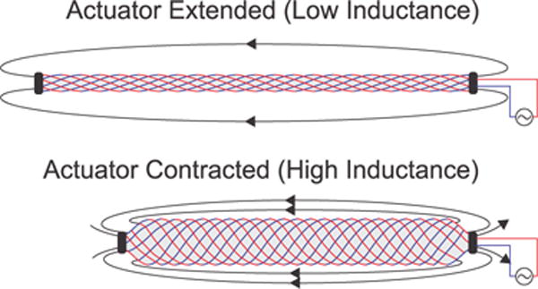
By using wire in place of the typically-non-conductive fibers of a pneumatic artificial muscle, one can create a “Smart Braid” that senses the contraction of the actuator. This is accomplished by measuring the inductance of the circuit formed by the wires in the braid. As the actuator contracts, the increasing alignment of the wires leads to a higher inductance.
The simplest way to model the change in inductance is to approximate the circuit as a long solenoid. Its inductance can then be approximated by
| (1) |
where μ is the magnetic permeability of the core and N is the number of turns. A and l are the cross-sectional area and the length, respectively. When a McKibben muscle is pressurized, its volume increases. The reinforcing fibers cause the length of the actuator to decrease as its cross-sectional area expands. The number of turns remains constant. The shortening and widening of the actuator lead to an increase in inductance. This makes the inductance of the circuit sensitive to the contraction of the actuator–with the inductance more than doubling over the course of a full contraction. In our pilot work [27], we showed that it is possible to use the inductance of the braid to measure contraction and proposed the long solenoid approximation as a modeling tool. In that work, the actuator length could only be accurately related to joint measurements by considering both inductance and resistance. In the present work, we have improved the actuator connections and manufacturing method, proposed a new modeling method based on the Neumann formula, experimentally validated the accuracy of both the long solenoid approximation and the Neumann formula, characterized the dynamic performance of the sensor, and tested the sensor alongside steel. This has allowed us to demonstrate how a simple, linear calibration of inductance alone can be used to measure contraction in quasistatic, loaded, and dynamic conditions. We found that the entire, 57 mm, actuator contraction can be measured with a linear function of the inductance (R2 = .9996). A large load (5 kg), resulted in only a millimeter of sensor bias. The sensor performance did not degrade at actuation frequencies up to 4 Hz. A 31 cm long steel cylinder with a 1.6 cm diameter placed next to the sensor, on average, biased the measurement by less than 0.3 mm.
II. MODELING
To enable a systematic design of Smart Braid sensors, we developed two models for predicting changes in inductance. Both predictions rely on kinematic models of fiber orientation during the PAM contraction. The long solenoid approximation provides an easy-to-compute, closed-form equation for inductance. Its applicability is unique to the solenoid-like structure of Smart Braid sensors on PAM actuators. The Neumann formula provides a way to predict changes in inductance for a broader class of deforming circuits. We validated these models with a custom-built, Smart Braid sensor.
A. Braid Model
In our kinematic model, we use simple, trigonometric relationships for the fibers in the braid [28]. This approximates the structure of the PAM as a long cylinder and neglects the effects of the tapering that occurs at the ends of the actuator in contracted conditions. This model also assumes that the fibers in the braid are inextensible. The length l and diameter D of the braid can be written in terms of the fiber angle θ with respect to the long axis of the actuator, the length b of the helices of the braid, and the number of turns n that each helix makes around the axis:
| (2) |
| (3) |
This relationship is illustrated in Fig. 2a. For PAMs, the helix length b and the number of turns n remain constant throughout the actuator contraction. Their values can be defined by the length le, diameter De, and winding angle θe of the fully-extended actuator. The helix length is given by:
| (4) |
and the number of turns of each helix by
| (5) |
These equations provide a simple way to use the constant fiber length assumption to predict the length, cross-sectional area, and fiber-orientation during the actuator contraction.
Fig. 2. Braid Model and Neumann Formula.
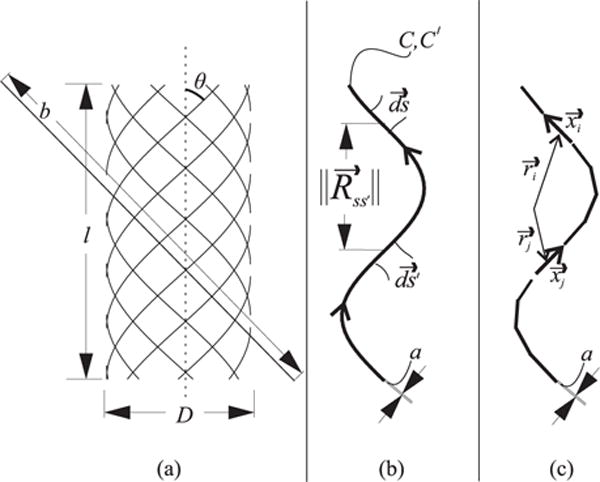
The braid is modeled as a series of cylindrical helices (a). The length of the curve that makes up each helix is given by b. The angle of this curve with respect to the cylinder axis is given by θ. l and D define the the length and diameter of the cylinder, respectively. The Neumann formula evaluates the relationship between differential elements in the current path. The inductance is calculated using the alignment of the segments and the distance between them. (b) shows a simple, helical current path defined by C made up with differential elements . In the integral form, an identical path C′ is defined. This path is made up with elements . The inner product of the segments is divided by the distance between them. The integral can be evaluated numerically by dividing the path into k segments (c). The length and orientation of the segments is given by and the center point of the segments is given by .
B. Long Solenoid Approximation
The long solenoid approximation assumes that the length of the sensor is much larger than the cross-sectional area. Furthermore, it assumes that the current always circles the axis perpendicularly in the same direction and that the profile of the braid is cylindrical. Solenoids with a short length (compared to the diameter) will have an inductance that is over-predicted by this approximation [29]. By combining the long solenoid equation (1) with the equations for braid contraction, one can predict how the inductance of the braid will change with actuator contraction. To approximate the inductance of the braid at a given fiber angle, θ, (1) can be evaluated in terms of the cross-sectional area, A, given by (3) and the length of the actuator given by (2). The number of turns made by the complete circuit N is equal to the product of the number of turns made by each helix, n, and the number of helices, nh, that make up the braid. The equation can be written in terms the ratio between the current actuator length l and its fully-extended length le, [27]:
| (6) |
Despite the non-linear terms, for a Smart Braid McKibben muscle with a winding angle of 20°, the change in inductance from the fully extended to the fully contracted condition (θ = 54.7°) is predicted to be approximately linear with respect to the actuator length (R2 = 0.9935).
C. Neumann Formula
While the long solenoid approximation is useful for PAM actuators, not all fiber-reinforced actuators have circular cross-sections or rely on helical fibers. Bending actuators recently developed at Harvard University, for instance, have semicircular cross-sections [5], [6]. Other actuators, that contract in a similar fashion to PAMs, rely on fibers that run parallel to the actuator axis [23], [30]. For the methods proposed in this work to be applied to these actuators, a more general method of inductance modeling is necessary.
The mutual inductance equation formulated by Franz Ernst Neumann, provides an expression for the mutual inductance of two current-carrying wires in terms of curve integrals. [31]. This expression does not rely on any of the assumptions of the long solenoid equation. Instead, Neumann’s original equation assumes infinitesimally thin current-carrying filaments. The original equation can be reformulated to provide an expression for the self-inductance of a single loop of wire with finite thickness [32]. The reformulation assumes that the current path, C, has no sharp corners and that the length of the current path, ‖C‖, is much greater than the radius of the wire, a. The order of the error of this method scales with the product of the magnetic core permeability μ and the wire radius a [32]. The current path C is broken into differential elements ds. The self-inductance is expressed by a double curve integral over C:
| (7) |
The inductance is calculated from the relationship between each differential element of the path C and with all the other differential elements making up the same path C′. The integral is only evaluated when the distance between the differential elements is greater than half the wire radius. The terms of the equation are illustrated in Fig. 2b. The inductance is high when many pairs of differential elements ( and ) are aligned and have a small distance between them. Y is a correction factor that depends on the current distribution in the wire. At very high frequencies of current, the skin effect will cause the current to become concentrated on the surface of the wire (Y = 0). At lower frequencies, the current will be more evenly distributed in the wire (Y = 0.5).
To evaluate (7) numerically, the path of the current can be divided into a series of k segments, with length and orientation defined by and center point location defined by . This is illustrated in Fig. 2c.
| (8) |
To speed up the computational evaluation of this expression, we can rewrite it to evaluate each pair of segments only once. This is accomplished by setting j to begin at i rather than at one and doubling the addend:
| (9) |
This is possible because of the commutative property of the inner product. This method of calculating inductance does not require that the circuit have a solenoid-like structure. We have made an implementation of (9) available on the MATLAB file exchange [33].
D. Model Validation
To validate both models, we measured the inductance of a Smart Braid sensor at a variety of lengths. These measurements were compared to the predictions of the long solenoid approximation and Neumann formula. In these predictions, the length-diameter relationship of the braid was assumed to be governed by (2) and (3). We identified the braid’s helix length and number of turns to be approximately 34 cm and 3.374, respectively. Figure 3 illustrates the models alongside the experimental sensor. The radial thickness of the Smart Braid was taken to be equivalent to two wire diameters. This makes the diameter of the equivalent long solenoid the outer diameter of the core plus two wire diameters (Fig. 3a). For the Neumann formula, the braid was modeled as eight, inner, right-handed helices and eight, outer, left-handed helices (Fig. 3b). The diameter of the inner helices was taken to be the diameter of the core plus one wire diameter. The diameter of the outer helices was taken to be the diameter of the core plus three wire diameters. The curve defining each of the 16 helices was divided into 104 finite elements (16 × 104 total elements). The self-inductance of the circuit was calculated using (9). Inductance was calculated assuming both a uniform current distribution in the wires (Y = 0.5) and surface-current (Y = 0). For each model, the magnetic permeability of vacuum was used for the core (μ = 4π × 10−7).
Fig. 3. Model Validation.
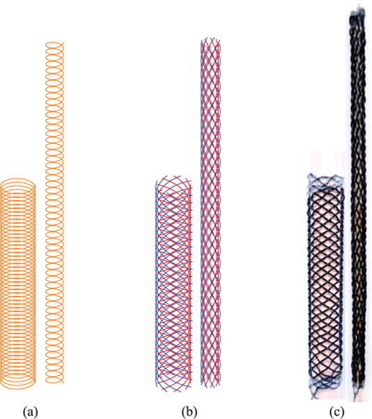
We model the inductance of the Smart Braid with either a simple long solenoid (a) or by using the Neumann formula on 16 helices (b) that are radially distributed about the actuator and electrically connected in series. The path of the current between the helices is not modeled. We compared these models of inductance with measurements from a Smart Braid stretched over dowels of different diameter (c).
For the model validation experiments, the Smart Braid sensor was only a wire braid, with no inner, elastomeric bladder. This allowed us to maintain the cylindrical sensor shape assumed by the long solenoid equation. The length was changed by stretching the braid over a series of cores with different diameters (Fig. 3c). Wooden dowels were used because they are non-magnetic with a magnetic permeability that is practically identical to that of vacuum. Seven dowels were used with the following nominal diameters: 6.35 mm, 9.53 mm, 12.70 mm, 15.88 mm, 19.05 mm, 22.23 mm, 25.40 mm. The braid was stretched over each dowel three times. The 21 trials were conducted in random order. In each trial, the length of the braid was measured once and 100 inductance measurements were taken.
Figure 4 shows the inductance measured in the experiments alongside the inductance predicted by the long solenoid approximation and Neumann formula. Performing a linear regression on the data allows one to characterize the sensitivity across the contraction range. This averaged sensitivity of the Smart Braid to contraction measured in the experiments was 6.71×10⁻⁸ . Over the same contraction range, the long solenoid approximation and the Neumann formula predicted sensitivities of 7.78×10⁻⁸ and 6.66×10⁻⁸ , respectively. The sensitivity of the Neumann formula is the same for the Y = 0.5 and Y = 0 conditions. The predicted inductance between the two current conditions varies with a constant offset.
Fig. 4. Results of Modeling Methods.
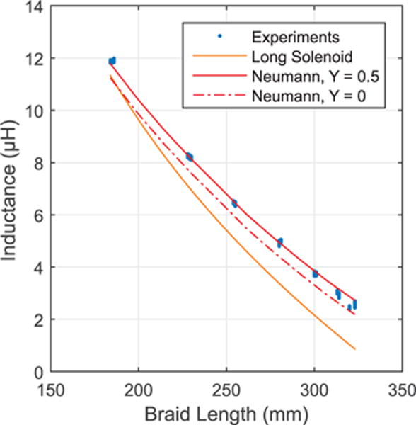
Each of the models of inductance predicts that the inductance of the Smart Braid decreases with increasing length. The sensitivity predicted by the Neumann formula is within 1 % of the sensitivity of the experimental data. The long solenoid approximation is more accurate than the Neumann formula at contracted braid lengths.
III. MATERIALS AND METHODS
We created a complete PAM actuator by affixing a new Smart Braid sensor over a flexible silicone tube. In addition to sensing contraction, the fibers of the Smart Braid reinforce the elastomeric bladder and cause the actuator to contract as the pressurized air pushes the volume of the bladder to expand. We tested the performance of the sensor under loaded and dynamic actuator contractions. additionally, we tested the sensor alongside steel.
A. Prototyping of the Smart Braid Actuator
The braid was created by weaving wire over a 3D-printed template. The template was printed with “ABSplus” from a Stratasys Dimension Elite printer. The template was designed to affix to a dowel during the braiding process. After the braid was completed, the dowel was removed and the template was collapsed and removed from within the braid. The template was designed so that, once removed, the braid would be 30 cm long with a winding angle (θe) of 20 ° when surrounding a silicone tube with an outer diameter of 9.5 mm. The braid was made up of eight right-handed helices and eight left-handed helices. We used ultra-flexible wire with soft copper stranding and PVC insulation with a conductor area of 0.33 mm2 (22 AWG, DABURN, #2671, Outer diameter 1.346 mm). A single strand of wire was woven to form the entire braid. The Smart Braid was stretched over a silicone tube with a 9.53 mm outer diameter (6.35 mm inner diameter) and connected to the test stand. The hose clamps required to attach the Smart Braid actuator to the test stand reduced the length of active, fully-extended portion of the actuator to 29 cm. Fabrication details, a bill of materials and 3D files are available in the supplementary files to this work and on the “Soft Robotics Toolkit” [34].
B. Instrumentation
We tested the actuator in a custom-made test apparatus in which we applied different pressures and loads while measuring both inductance and the ground truth actuator contraction. Pressure control was achieved with a custom feedback loop driven by a proportional valve (Enfield LS-V05s) and a pressure transducer (WIKA A-10). Contraction of the actuator was measured from the motion of a sliding carriage affixed to the actuator end. A string potentiometer was used to measure the position of the carriage (UniMeasure LX-PA, 10” range). Figure 5 shows the test-stand assembled with the actuator. The inductance of the braid was measured with an LCR meter (NI PXI-4072) with an effective excitation frequency of 30 kHz and a maximum sampling rate of 40 Hz [35]. The LCR meter works by comparing the magnitude of the sensor impedance at low and high frequencies [36]. Test stand sensor measurements and control signals were processed with a data acquisition unit (NI PXIe-6341). The LCR meter and data acquisition unit used a PXI express chassis (NI PXIe-1073) to communicate with custom scripts in LabVIEW. The test stand used to characterize the sensor performance was adapted from the test stand used in our prior work [27]. The primary difference is that the connections between the actuator and test fixture were made stiffer. Also, the LCR meter used in this work has a faster sampling rate.
Fig. 5. Test Stand.
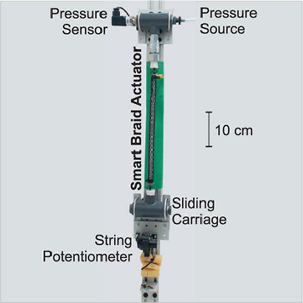
A custom-made test stand was used to characterize the inductance-length relationship of the Smart-Braid actuator. The actuator is contracted by filling the inner bladder with pressurized air. The top side of the actuator is fixed and the bottom is attached to a sliding carriage. Weights can be attached to the carriage to load the actuator. We measure the inductance of the Smart Braid with an LCR meter. A ground truth measurement of contraction is obtained from a string potentiometer attached to the carriage.
C. Sensor Calibration
To calibrate the sensor, inductance measurements were collected while the gauge pressure in the actuator was increased gradually to 0.34 MPa (49 psi) and then decreased to atmospheric levels over the course of 200 seconds. The shortest recorded actuator length was 232.5 mm which corresponds to a contraction of approximately 20 %. To calibrate the sensor, the inductance measurements taken during the contraction and extension cycle were fit with a linear regression to the actuator length measured with the string potentiometer attached to the sliding carriage. Figure 6 shows the inductance and position measurements taken during the calibration and their linear regression. The calibration resulted in a strong linear fit (R2 = 0.9996). The linear function predicting the actuator length l (in millimeters) from the inductance measurements L (in henries) is given by
| (10) |
This corresponds to a sensitivity of 6.81×10⁻⁸ .
Fig. 6. Sensor Calibration.
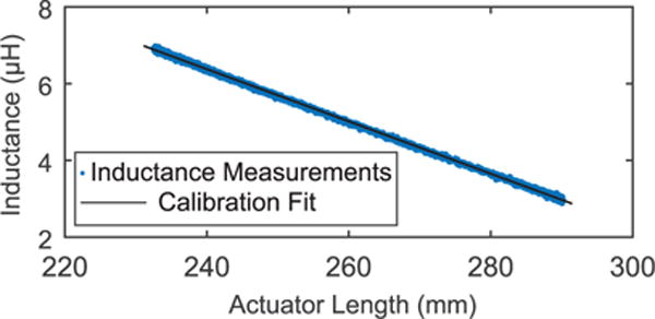
To specify the sensor characteristic, experimental calibration data was fit with a linear function (R2 = 0.9996).
D. Sensor Performance Verification
1) Loaded Conditions
To evaluate how an end-load would affect the correlation between the lengths predicted by the Smart Braid and the length measured at the sliding carriage, the actuator was tested with a series of weights (0 to 5 kg in 1 kg increments) attached to the sliding carriage. The contraction of the actuator was driven by the same pressure sequence used in the calibration. The load caused the degree of contraction to decrease under the same pressure conditions. The pressure contraction relationship is illustrated in Fig. 7 for the no load and 5 kg tests. After the 5 kg test, the actuator was again tested without any weight. Thus a total of seven weight trials were conducted. In each weight condition, we calculated the mean and standard deviation of the error between the length calculated by the inductance of the Smart Braid and the length measured at the sliding carriage.
Fig. 7. Contraction of the Loaded Actuator.
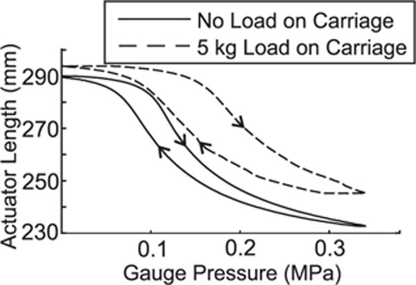
Adding an end-load to the actuator decreases the actuator contraction that can be achieved with the same pressure. This behavior is similar to other actuators of this kind [20].
2) Dynamic Conditions
To evaluate the usefulness of the Smart Braid under dynamic actuation conditions, the performance of the sensor was evaluated at a series of actuator contraction frequencies. The contractions were driven by sinusoidal pressure profiles. The gauge pressure was first varied between approximately 0.013 MPa and 0.33 MPa at a frequency of 0.25 Hz for 20 seconds. The frequency was then increased in 0.25 Hz increments up to 4 Hz. At each frequency setting, data was collected for 20 seconds. Because inductance measurements were not available more frequently than 40 Hz, the actuator frequency was not increased beyond 4 Hz. Valve flow limitations caused the magnitude of the pressure change to decrease gradually as the frequency increased. The gauge pressure at the highest frequency varied between approximately 0.14 MPa and 0.2 MPa. The frequency response of the Smart Braid inductance measurements to the actuator length (as measured at the sliding carriage) was characterized at the test frequencies using spectral analysis in MATLAB’s System Identification Toolbox. Only one dynamic sequence was performed.
3) Proximity to Ferromagnetic Materials
To test whether the sensor would be affected by proximity to ferromagnetic materials, we placed steel rods next to a Smart Braid sensor. This was done concurrently with the model verification tests. The braid was stretched over a wooden dowel and 100 inductance measurements were taken without any steel nearby. Then, a steel cylinder with a 1.59 cm diameter and 11.2 cm length was rested alongside the middle section of Smart Braid. The long edge of the steel cylinder was touching the insulated wires of the Smart Braid. 100 inductance measurements were collected with the steel cylinder next to the braid. Then, the cylinder was removed and a larger steel cylinder with the same diameter but a length of 31 cm was placed next to the sensor in the same way and 100 more inductance measurements were collected.
IV. RESULTS
Over the course of the actuator contraction, the inductance of the Smart Braid increased from 2.96 μH to 6.88 μH. Repeating the calibration conditions (Fig. 8, 0 kg) resulted in a measurement error with a standard deviation of 0.83 mm. The fit of the linear regression to the calibration data is excellent (R2 = 0.9996). The residual of the calibration is defined as the difference between the calibration measurements and the calibration fit. The standard deviation of the residual was 0.48 mm. Moreover, the sensitivity of this calibration is very similar to the sensitivity predicted by our numerical models. To validate our models, the inductance of a 30 cm cylindrical Smart Braid, over a larger contraction range, was predicted by integrating the Neumann Formula (9). The sensitivity was found to be 6.66×10⁻⁸ . The calibration of the Smart Braid actuator exhibited a sensitivity to contraction of 6.81×10⁻⁸ . In this work only 29 cm of the braid was able to contract. At the maximum, unloaded contraction, approximately 13 % of the 29 cm unconstrained braid had a tapering diameter.
Fig. 8. Force Dependency.
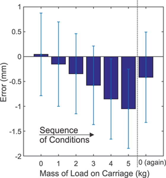
Increasing the load on the sliding carriage caused the inductance-based measurements to diverge slightly from the string-potentiometer readings. This is potentially due to compliance in the connections between the actuator (where the inductance of the Smart Braid is measured) and the sliding carriage (where the string potentiometer is attached). Shown are means of the error plus/minus a single standard deviation. When the load was removed, some bias remained.
When loads were added to the carriage, a slight difference was observed between the length calculated by the Smart Braid inductance measurements and the length measured at the sliding carriage. This difference increased with the load. At the highest load (5 kg) the mean error between the sensors was −1.05 mm. When the no load condition was repeated after the 5 kg test, the mean error between the sensors was −0.41 mm. Figure 8 illustrates this sensor bias. Figure 9 shows the deviation between the sensor measurements in the 5 kg condition.
Fig. 9. 5 kg End Load.
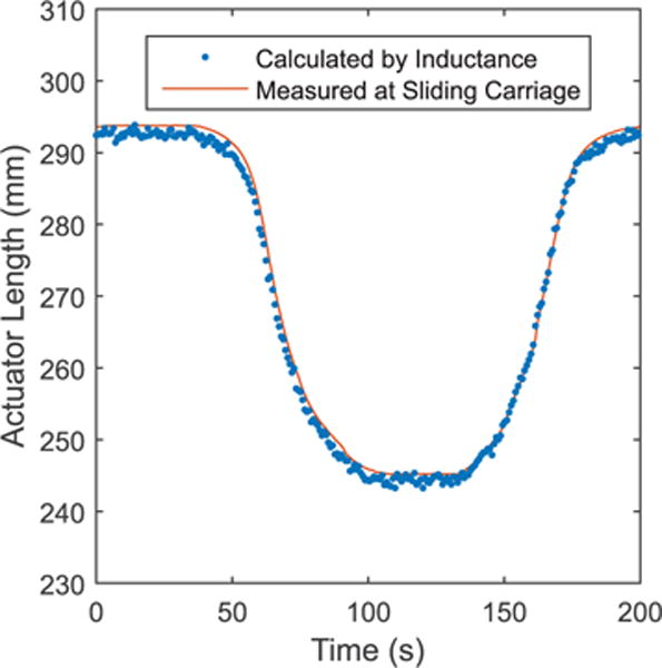
Shown are a series of measurements during the contraction-extension cycle with a 5 kg load. The Smart Braid reliably reports position with an average error of 1 mm.
The dynamic tests showed virtually no phase lag or change in magnitude response for frequencies up to 4 Hz. A bode plot of the spectral analysis of the Smart Braid sensor response is shown in Fig. 10. The uncertainty of the magnitude response increased as the samples per cycle became sparser. A representative snippet of the sensor measurements at 4 Hz is shown in Fig. 11. A video with portions of the dynamic test is included in the supplementary materials.
Fig. 10. Frequency Dependency.
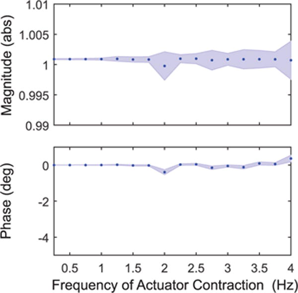
The Smart Braid sensor provides accurate measurements over a broad dynamic range. For frequencies up to 4 Hz there is neither substantial attenuation nor phase lag. The dots show results of a spectral analysis at 16 different frequencies. The lightly shaded bands show the bounds corresponding to three standard deviations.
Fig. 11. 4 Hz Pressure Signal.
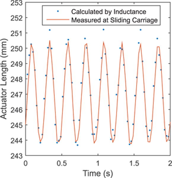
Even at rapid actuator contractions, the Smart Braid sensor provides a reliable length measurement. No phase lag or attenuation can be observed.
The inductance measurements of the Smart Braid sensor next to a steel rod were only slightly different than the inductance measurements of the sensor alone. Over the 21 braid conditions that were tested with the shorter cylinder, the average absolute change in inductance was 7.32×10⁻⁹ H. The largest change in measured inductance with the shorter cylinder was an increase of 3.38×10⁻⁸ H when the braid was stretched over the 6.36 mm diameter dowel. With the long rod, the average absolute change was 1.99×10⁻⁸ H and the largest change was 9.65×10⁻⁸ H (when the braid was stretched over the 22.23 mm diameter dowel). Multiplying these changes by the sensitivity of the sensor, suggests an average bias for the short and long rods of 0.1 mm and 0.3 mm, respectively. The largest changes in inductance we observed would suggest corresponding biases of 0.5 mm and 1.4 mm for the short and long rods.
V. DISCUSSION AND CONCLUSIONS
We proposed to use the braid of a McKibben muscle to sense the actuator contraction. The Smart Braid we tested was able to measure the actuator contraction to within about a millimeter in dynamic and loaded conditions. This was accomplished without any additional mechanical components. The electrically conductive circuit formed by the fibers is the only difference from a standard McKibben muscle. Despite this simplicity, the contraction can be accurately measured with only a linear calibration of the inductance measurements. The Smart Braid can provide measures of length at contraction frequencies beyond the typical bandwidth of PAM actuators [37]–[39].
The models we propose are useful for designing Smart Braid sensors. The sensitivity of the Smart Braid sensor we tested across a large extension range is within 1 % of the sensitivity predicted by the Neumann formula. This suggests that the Neumann formula will be useful in designing Smart Braid sensors beyond our particular prototype. Though the predicted sensitivity was similar, the Neumann formula consistently under-predicted the measured inductance by approximately 1.6 μ H. The Neumann formula error grows with the thickness of current-carrying wires. The nearly constant under-prediction could be due to the thickness of the wires used in the sensor.
In contrast to the computationally expensive Neumann formula, the long solenoid approximation is closed-form. This approximation becomes increasingly accurate as the angle of the wires increases (as the length of the braid decreases). This increased accuracy is expected because the long solenoid approximation assumes that the angle of the wires is close to 90°.
With a 5 kg load, we observed a bias of approximately 1 mm between the actuator-level measures of the Smart Braid and joint-level measurements. We believe this is caused by compliance in the actuator connections. Not all of this stretching was recoverable; after the mass was removed, the sensor still exhibited a half-millimeter bias. Stretching in the connections is a weakness of any actuator-level sensing method. There are several possible ways to resolve this. The first is to make the connections as stiff as possible. Another way is to use redundant sensor measurements. PAMs are commonly used in antagonized configurations. An antagonized pair would provide a degree of sensor redundancy to help correct for the small biases. Finally, one could compensate for the bias by measuring the magnitude of the end-load. This can be achieved, for example via a pressure sensor. Alternatively, our prior work explored using the resistance-strain relationship of the wires to measure the actuator force output directly from the Smart Braid [27].
Steel near the sensor had only a small effect on the measured inductance. The small effect is expected because the flux of a solenoid is concentrated in the core. This suggests that these sensors can function in conjunction with relatively large ferromagnetic parts in close proximity to the sensors. We would expect non-magnetic metals to have a smaller effect than steel. The inductance of the sensors was modeled with a vacuum core. As is expected, non-magnetic materials in the core like wood, rubber and air did not affect the sensor inductance. We would not expect fluids, like water or oil, to change the inductance. Water is diamagnetic but the change in core permeability would be smaller than 0.001 %. This means that Smart Braid actuators could be used in hydraulic or pneumatic systems.
In this work, we did not model the effect of the hose clamps on the Smart Braid or the resulting tapering at the ends of the actuator. Despite this, the sensitivity predicted by the Neumann formula was only 2.2 % different than the sensitivity of the Smart Braid actuator. The diameter constraints of the hose clamps and the tapering of the diameter did not greatly affect the predictive ability of our models because only about 16 % of the actuator had a tapered or constrained diameter (3.77 cm tapered and 1 cm constrained of the 30 cm braid). If these effects were to be considered in the future, the Neumann formula could be used in combination with a more complex braid model. In this work the sensitivity of the Smart Braid actuator was 6.8×10⁻⁸ . In our previous work, a similar, 20° winding angle, actuator exhibited a sensitivity of 6.9×10⁻⁸ [27].
Smart Braids are not the only proposed method of measuring actuator contraction within the structure of a soft actuator. Whereas Smart Braids require a modification to the reinforcing fibers, other embedded sensing techniques have relied on specially made elastomers. Goulbourne and Son tested cylindrical dielectric elastomers in extension and found a linear sensor response [22]. They postulated that these sensors could be useful in McKibben muscles [40]. The dielectric elastomer in these experiments was constructed using carbon grease to create electrodes on the surfaces of an elastomer. Elastomers such as these have the intriguing possibility of serving as both sensor and actuator [41], [42]. The authors of this work have found no published record of experiments testing the use of dielectric elastomers in a fiber-reinforced actuator (though dielectric elastomers have been used as an external transducer for the actuators [25], [26]).
One method of sensing actuator contraction that has been experimentally validated is the addition of microchannels filled with conductive liquid in a sheath about the actuator. The strain in the sheath causes a change of resistance. Park and Wood developed a sensor of this kind with a sensitivity much greater than the sensor in this work [23]. We define geometric sensitivity as the normalized change in the measured property over the strain in the actuator. Data by Park and Wood suggest a geometric sensitivity of 12.9 whereas the sensor in this work exhibited a geometric sensitivity of 2.9. Similar microchannels have shown large changes in resistance when subjected to external pressures [43]. This suggests that length measurement of a soft actuator with a sheath like this could become biased by external forces on the side wall of the actuator.
Smart Braid actuators will be useful for robotic devices. Small ICs [44] could be employed for accurate inductance measurement. The sensors could be shielded to prevent electromagnetic interference. The manufacturing process could be automated by winding conductive wires around a tube that provides a winding guide on its surface. The wires could then be encased with an additional elastomer layer [3], [5], [6]. The technique proposed in this work, of using conductive fibers to provide both sensing and reinforcement roles, could be applied to other types of fiber-reinforced actuators as well. The Neumann formula modeling technique would be particularly useful for making these actuators self-sensing. Smart actuators like these will further accelerate the adoption of soft fluidic actuators in continuum manipulators, soft orthosis, and compliant robots.
Supplementary Material
Acknowledgments
Thanks to Kevin Green for the modeling of our 3D printed guide used to weave the braid. Funding for this project was provided by NIH (GRANT: 1-R01-EB019834-2014 Wearable eMbots to Induce Recovery of Function). This material is based upon work supported by the National Science Foundation Graduate Research Fellowship under Grant No. DGE 1256260. Any opinion, findings, and conclusions or recommendations expressed in this material are those of the authors(s) and do not necessarily reflect the views of the National Science Foundation.
Biographies

Wyatt Felt is a PhD candidate and National Science Foundation Graduate Research Fellow at the University of Michigan, Ann Arbor, MI, USA. He was born in Provo, UT, USA and there received a B.S. in mechanical engineering in 2013 from Brigham Young University (BYU) where he was a Crocker Innovation Fellow.
Prior to the commencement of his PhD, he worked as Head of Product Development at Owlet Baby Monitors (owletcare.com). He has worked as an intern at the National Renewable Energy Laboratory and iRobot Corporation.
Mr. Felt is a member of Tau Beta Pi and an Elder in The Church of Jesus Christ of Latter-day Saints.

Khai Yi Chin was born in the state of Selangor, Malaysia, on 1993. He is in the process of obtaining the B.S. degree in mechanical engineering from the University of Michigan, Ann Arbor, MI, USA, in 2016.

C. David Remy is Assistant Professor of Mechanical Engineering at the University of Michigan, Ann Arbor. He received his Ph.D. from ETH Zurich, and holds both a M.Sc. in Mechanical Engineering from the University of Wisconsin and a Diploma in Engineering Cybernetics from the University of Stuttgart. Dr. Remy is the head of the Robotics and Motion Laboratory (ram-lab.engin.umich.edu). His research interests include the design, simulation, and control of legged robots, exoskeletons, and other nonlinear systems. Drawing inspiration from biology and biomechanics, he is particularly interested in the effects and exploitation of natural dynamic motions, the role of different gaits, and the possibility of force/torque controllable systems; both in conceptual models and in hardware realizations.
References
- 1.Krishnan G, Bishop-Moser J, Kim C, Kota S. Kinematics of a generalized class of pneumatic artificial muscles. J Mech Robot. 2015;7(4):041014. [Google Scholar]
- 2.Bishop-Moser J, Kota S. Design and modeling of generalized fiber-reinforced pneumatic soft actuators. IEEE Trans Robot. 2015 Jun;31(3):536–545. [Google Scholar]
- 3.Connolly F, Polygerinos P, Walsh CJ, Bertoldi K. Mechanical programming of soft actuators by varying fiber angle. Soft Robot. 2015;2(1):26–32. [Google Scholar]
- 4.Suzumori K, Iikura S, Tanaka H. Development of flexible microactuator and its applications to robotic mechanisms. Proc IEEE Int Conf Robot Autom. 1991:1622–1627. [Google Scholar]
- 5.Galloway KC, Polygerinos P, Walsh CJ, Wood RJ. Mechanically programmable bend radius for fiber-reinforced soft actuators. Proc 16th Int Conf Adv Robot. 2013:1–6. [Google Scholar]
- 6.Polygerinos P, Wang Z, Overvelde JT, Galloway KC, Wood RJ, Bertoldi K, Walsh CJ. Modeling of soft fiber-reinforced bending actuators. IEEE Trans Robot. 2015 Jun;31(3):778–789. [Google Scholar]
- 7.Paynter HM, Juarez J. Thermodynamic treatment of tug-&-twist technology. 2. Thermodynamic twistor design. Proc IEEE/ASME Int Conf Adv Intell Mechatron. 1999:826–829. [Google Scholar]
- 8.Bishop-Moser J, Kota S. Towards snake-like soft robots: Design of fluidic fiber-reinforced elastomeric helical manipulators. Proc IEEE/RSJ Int Conf Intell Robots Syst. 2013:5021–5026. [Google Scholar]
- 9.Grissom MD, Chitrakaran V, Dienno D, Csencits M, Pritts M, Jones B, McMahan W, Dawson D, Rahn C, Walker I. Design and experimental testing of the octarm soft robot manipulator. Proc Defense Security Symp. 2006:62301F-1–62301F-10. [Google Scholar]
- 10.Caldwell D, Tsagarakis N, Medrano-Cerda G. Bio-mimetic actuators: Polymeric pseudo muscular actuators and pneumatic muscle actuators for biological emulation. Mechatronic. 2000;10(4):499–530. [Google Scholar]
- 11.Daerden F, Lefeber D. Pneumatic artificial muscles: Actuators for robotics and automation. Eur J Mech Environ Eng. 2002;47(1):11–21. [Google Scholar]
- 12.Festo. Fluidic muscle [Online] 2007. Available: http://www.festo.com/cms/en_corp/9790.htm.
- 13.Niiyama R, Nagakubo A, Kuniyoshi Y. Mowgli: A bipedal jumping and landing robot with an artificial musculoskeletal system. Proc IEEE Int Conf Robot Autom. 2007:2546–2551. [Google Scholar]
- 14.Niiyama R, Nishikawa S, Kuniyoshi Y. Athlete robot with applied human muscle activation patterns for bipedal running. Proc IEEE-RAS 10th Int Conf Humanoid Robots. 2010:498–503. [Google Scholar]
- 15.Trivedi D, Rahn CD, Kier WM, Walker ID. Soft robotics: Biological inspiration, state of the art, and future research. Appl Bionics Biomech. 2008;5(3):99–117. [Google Scholar]
- 16.Sawicki GS, Ferris DP. A pneumatically powered knee-ankle-foot orthosis (KAFO) with myoelectric activation and inhibition. J Neuroeng Rehabil [Online] 2009 Jan;6(1):23. doi: 10.1186/1743-0003-6-23. Available: http://www.pubmedcentral.nih.gov/articlerender.fcgi?artid=2717982\&tool=pmcentrez\&rendertype=abstract. [DOI] [PMC free article] [PubMed] [Google Scholar]
- 17.Ueda J, Ming D, Krishnamoorthy V. Individual muscle control using an exoskeleton robot for muscle function testing. IEEE Trans Neural Syst Rehabil Eng [Online] 2010 Aug;18(4):339–350. doi: 10.1109/TNSRE.2010.2047116. Available: http://www.ncbi.nlm.nih.gov/pubmed/20363684. [DOI] [PubMed] [Google Scholar]
- 18.Wehner M, Quinlivan B, Aubin PM, Martinez-Villalpando E, Baumann M, Stirling L, Holt K, Wood R, Walsh C. A lightweight soft exosuit for gait assistance. Proc IEEE Int Conf Robot Autom. 2013:3362–3369. [Google Scholar]
- 19.Ando T, Kobayashi Y, Okamoto J, Takahashi M, Fujie MG. Intelligent trunk corset to support rollover of cancer bone metastasis patients. IEEE/ASME Trans Mechatronic. 2010 Apr;15(2):181–190. [Google Scholar]
- 20.Belforte G, Eula G, Ivanov A, Sirolli S. Soft pneumatic actuators for rehabilitation. Actuator. 2014;3(2):84–106. [Google Scholar]
- 21.Festo. Bionic handling assistant [Online] 2010. Available: http://www.festo.com/cms/en_corp/9655_10218.htm.
- 22.Goulbourne N, Son S. Numerical and experimental analysis of McKibben actuators and dielectric elastomer sensors. Proc ASME Int Mech Eng Congr Expo. 2007:175–185. [Google Scholar]
- 23.Park Y-L, Wood RJ. Smart pneumatic artificial muscle actuator with embedded microfluidic sensing. Proc IEEE Sensors. 2013:1–4. [Google Scholar]
- 24.Reininger T. U.S. Patent 7 104 182. Contractile unit having a position sensor means. 2006 Sep 12;
- 25.Nakamoto H, Oida S, Ootaka H, Tada M, Hirata I, Kobayashi F, Kojima F. Application of stretchable strain sensor for pneumatic artificial muscle. Proc IEEE Symp Robot Intell Informationally Struct Space. 2014:1–5. [Google Scholar]
- 26.Veale AJ, Anderson IA, Xie SQ. The smart peano fluidic muscle: A low profile flexible orthosis actuator that feels pain. presented at the Conf. Sensors Smart Structures Technologies Civil, Mechanical, Aerospace Systems; San Diego, CA, USA. 2015; p. 94351V. [Google Scholar]
- 27.Felt W, Remy CD. Smart braid: Air muscles that measure force and displacement. Proc IEEE/RSJ Int Conf Intell Robots Syst. 2014:2821–2826. [Google Scholar]
- 28.Chou C, Hannaford B. Measurement and modeling of McKibben pneumatic artificial muscles. Robotic. 1996;12(1):90–102. [Google Scholar]
- 29.Nagaoka H. The inductance coefficients of solenoids. J College Sci. 1909;27(3):1–33. [Google Scholar]
- 30.Tomori H, Nakamura T. Theoretical comparison of McKibben-type artificial muscle and novel straight-fiber-type artificial muscle. Int J Autom Techno. 2011;5(4):544–550. [Google Scholar]
- 31.Neumann FE. Allgemeine gesetze der induzierten elektrischen strme. 1845:1–87. [Google Scholar]
- 32.Dengler R. Self inductance of a wire loop as a curve integral. 2012 to be published. [Google Scholar]
- 33.Felt W. Self-inductance with Neumann formula [Online] 2015. Available: http://www.mathworks.com/matlabcentral/fileexchange/50708-self-inductance-with-neumann-formula.
- 34.Felt W, Chin KY, Green K, Remy CD. Soft robotics toolkit, “Smart Braids”—Conductive reinforcing fibers [Online] 2015. Available: http://softroboticstoolkit.com/book/smart-braids.
- 35.National Instruments. Capacitance/inductance measurements [Online] 2011. Available: http://www.ni.com/tutorial/3078/en/
- 36.National Instruments. NI FlexDMM measurement capabilities [Online] 2011. Available: http://www.ni.com/white-paper/3713/en/
- 37.Shen X. Nonlinear model-based control of pneumatic artificial muscle servo systems. Control Eng Practic. 2010;18(3):311–317. [Google Scholar]
- 38.Caldwell DG, Medrano-Cerda GA, Goodwin M. Control of pneumatic muscle actuators. IEEE Control Syst. 1995 Feb;15(1):40–48. [Google Scholar]
- 39.Gordon KE, Sawicki GS, Ferris DP. Mechanical performance of artificial pneumatic muscles to power an ankle–foot orthosis. J Biomech. 2006;39(10):1832–1841. doi: 10.1016/j.jbiomech.2005.05.018. [DOI] [PubMed] [Google Scholar]
- 40.Goulbourne N, Son S, Fox J. Self-sensing McKibben actuators using dielectric elastomer sensors. Proc 14th Int Symp Smart Struct Mater Nondestructive Evaluation Health Monit. 2007:652 414-1–652 414-12. [Google Scholar]
- 41.Anderson IA, Gisby TA, McKay TG, O’Brien BM, Calius EP. Multi-functional dielectric elastomer artificial muscles for soft and smart machines. J Appl Phys. 2012;112(4):041101. [Google Scholar]
- 42.York A, Seelecke S. Towards self-sensing of deap actuators: Capacitive sensing experimental analysis. Proc ASME Conf Smart Mater, Adaptive Struct Intell Syst. 2010:307–314. [Google Scholar]
- 43.Vogt DM, Park Y-L, Wood RJ. Design and characterization of a soft multi-axis force sensor using embedded microfluidic channels. IEEE Sensors J. 2013 Oct;13(10):4056–4064. [Google Scholar]
- 44.Texas Instruments. LDC1000 inductance-to-digital converter, datasheet (Rev. B) [Online] 2015. Available: http://www.ti.com/lit/ds/symlink/ldc1000.pdf.
Associated Data
This section collects any data citations, data availability statements, or supplementary materials included in this article.


