Abstract
Currently, cylindrical beams with radial or azimuthal polarization are being used successfully for the optical manipulation of micro- and nano-particles as well as in microscopy, lithography, nonlinear optics, materials processing, and telecommunication applications. The creation of these laser beams is carried out using segmented polarizing plates, subwavelength gratings, interference, or light modulators. Here, we demonstrate the conversion of cylindrically polarized laser beams from a radial to an azimuthal polarization, or vice versa, by introducing a higher-order vortex phase singularity. To simultaneously generate several vortex phase singularities of different orders, we utilized a multi-order diffractive optical element. Both the theoretical and the experimental results regarding the radiation transmitted through the diffractive optical element show that increasing the order of the phase singularity leads to more efficient conversation of the polarization from radial to azimuthal. This demonstrates a close connection between the polarization and phase states of electromagnetic beams, which has important implications in many optical experiments.
Introduction
Phase singularities of a scalar field, which include vortex phases and phase jumps, are important features of various types of waves1, 2. Vector fields also exhibit a variety of polarization singularities3, 4. The spin angular momentum of photons was detected a long time ago5–7, and its interrelation with the orbital angular momentum has been discussed in several recent reviews2, 4, 8–14. Light beams with defined phase and polarization features are important for many applications, including optical manipulation15–17, microscopy18–20, materials processing21–24, and telecommunications25–27. Cylindrically polarized optical beams, which may have a radial or azimuthal polarization, have attracted the most attention from researchers because of their special properties12.
In some applications, such as STED (Stimulated Emission Depletion Microscopy) methods20, it is important to use a specific combination of laser beam polarization and spatial properties. In other applications, a desired state of polarization during the propagation of the beam must be retained, for example, to increase network throughput by using fibre modes that carry orbital angular momentum27. Polarization distribution control of the laser radiation enables some unique methods, like the selective excitation of an anisotropic molecule, focusing on a size smaller than the diffraction limit, and the fabrication of periodic nanostructures with femtosecond laser light22, 23, 28.
The conversion of polarization type can take place when beams with a phase singularity are tightly focused29–31. The transfer of angular momentum from the spin degree of freedom (which is related to the state of polarization) to the orbital (which is relevant to the phase distribution) degree of freedom can also occur in anisotropic media32–35. The interaction of the polarization singularities and phase singularities is used to detect the polarization state of the laser beam36, 37. Note that a complete differentiation of polarization types is only possible when the light is sharply focused37.
In this paper, we demonstrate the conversion of polarization type in a cylindrically polarized laser beam by introducing a higher-order vortex phase singularity. Earlier, a polarization distribution change for a vortex radially polarized beam in the propagation was shown12, 38, 39. However, the effects of a higher-order vortex phase in a cylindrical vector beam have not been previously studied. Here, the phenomenon of an orthogonal transformation in polarization is described empirically for the first time. The effect of the conversion of an azimuthally polarized beam to a radially polarized beam, and vice versa, is apparent even with weak focusing (in the paraxial case). A theoretical model for this phenomenon in focused cylindrical vector beams using the Debye approximation is also presented. In addition, a numerical study was performed, and the experimental results fully confirmed the theoretical predictions.
Results
Theoretical analysis of polarization conversion
The sharp focusing of beams cannot be handled by the paraxial approximation and is usually solved by the Debye method40. The vector generalization of Debye theory is able to explain the behaviour of the polarization and intensity distributions of the electromagnetic field in the focal region. According to this method, the field distribution in the focal region is formed by wave rays that converge inside the cone bounded by the aperture of the optical system. Using the Debye approximation41, 42 for tight focusing, we obtain the following expression for the transverse components in the case of focusing an azimuthally polarized beam (as in this case, with no longitudinal component), having an m-th order vortex phase:
| 1 |
where (ρ, φ, z) are the cylindrical coordinates in the focal region, (θ, ϕ) are the spherical angular coordinates of the focusing system’s output pupil, α is the maximum value of the azimuthal angle related to the system’s numerical aperture, R(θ) is the incident beam, T(θ) is the pupil’s apodization function (equal to for aplanatic systems), is the wavenumber, λ is the wavelength, and f is the focal length (see Fig. 1).
Figure 1.
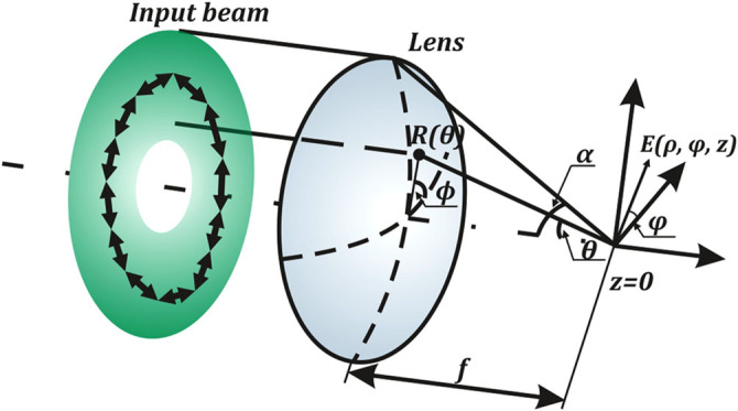
Vector Debye theory: focusing an azimuthally polarized beam through a lens of focal length f and maximum azimuthal angle α.
Equation (1) shows that the azimuthal polarization is retained only when focusing in the absence of a vortex phase (m = 0). When a vortex phase is present, part of the energy of the azimuthal component will be transferred to the orthogonal radial component. Let us determine the situation under which this transformation be most pronounced. To simplify the analysis, we consider the limits of integration in Eq. (1) to reflect a narrow ring θ ∈ [α 1, α 2], denoting the middle of the ring as .
Then, the ratio of the intensities of the orthogonal components in the focal region can be estimated by the following expression:
| 2 |
From Eq. (2), it is obvious that the intensity of the radial component will be greater than the azimuthal one when the following is true:
| 3 |
We can define the boundary of the region where the radial polarization dominates over the azimuthal with the following radius:
| 4 |
where j v,1 is the first zero of the v-th Bessel function of the first kind.
When |m| ≥ 2 at the central region of the focal plane, a radial, not azimuthal, polarization will be created. As the order of the vortex phase increases, this region will increase in size. Note also that the region of conversion shrinks as the numerical aperture of the focusing system increases (θ c → 90°). That is, in the paraxial case with a weak focus, this effect will be more significant.
Let us now consider the following incident optical beam:
| 5 |
where σ is the angular width of the waist of a Gaussian beam, and sin α is the numerical aperture of the focusing device.
Using certain approximations, including , we can transform the integral in Eq. (1) for a beam described by Eq. (5) into a form with tabular integrals43 and calculate it analytically.
Using the notation x = kρ sin σ, after mathematical transformations we obtain:
| 6 |
| 7 |
In this analysis, we do not take into account factors that do not depend on x and m because the module for both components is the same. The radial component is always positive for m > 0, and the azimuthal one changes sign once in this area. Because, for a constant argument, the function I m(·) decreases with increasing order, then we can show that in the region with positive values of , the radial component is greater than the azimuthal component.
Moreover, the inequality holds over a wider range. As proof, in Eq. (7), there is a difference of functions with orders that differ by one. The recurrence relation for orders that differ by two is known: . We use the monotonic continuity of the modified Bessel functions to write the following as an approximation:
| 8 |
By substituting Eq. (8) into Eq. (7), we obtain:
| 9 |
The ratio of the intensities, similar to Eq. (2), will be the following:
| 10 |
Because, as mentioned, the function I v(·) decreases with increasing order when the argument is held constant, we obtain .
When focusing a radially polarized field possessing an m-th order vortex phase, we obtain the following equation(in the paraxial case, we can consider only the transverse components):
| 11 |
In the paraxial case, we can consider only the transverse components. In this way, we obtain a situation opposite to the one that was discussed above. That is, the radial polarization is transformed into an azimuthal polarization. This effect gets stronger as the order of the optical vortex increases:
| 12 |
Numerical simulation
This section presents the results of simulating the polarization conversion using the Gaussian beam of Eq. (5) along with Eq. (1). For the numerical integration of Eq. (1), we chose the following parameters: sin α = 0.02, sin σ = 0.012.
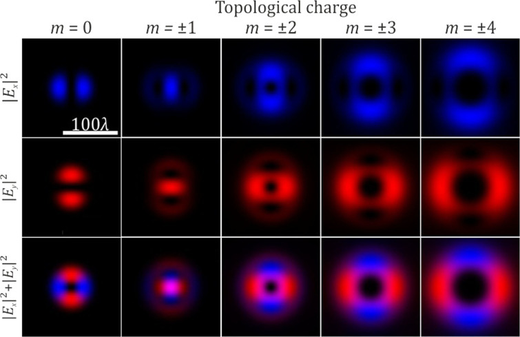
Figure 2 shows the intensity distribution in the focal plane for the focused radially polarized beam described by Eq. (11) for . As observed in the absence of a vortex phase (m = 0), an initial radially polarized beam preserves the polarization in the focal plane. If we add a vortex phase of the first order, of either sign, in the focused radially polarized beam, a bright spot with circular polarization will be formed in the focal plane. If we add a vortex phase of a higher order, the conversion from radial polarization to azimuthal is observed.
Figure 2.
The distribution of the various components of the electric field in the focal plane for a radially polarized incident beam in the absence and presence of a vortex phase (the x-component is blue and the y-component is red).
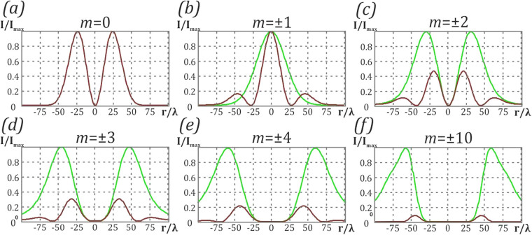
Figure 3 shows the focal distribution of the azimuthal and radial components of the electric field to quantitatively estimate the degree of conversion. We calculated the coefficient (see Eq. (12)) for different values of m to determine the degree of orthogonal polarization conversion. The values are , , , , , . As the order of the vortex increases, the contribution of the azimuthal component increases. However, even in the case of a 10-th order vortex, the radial component does not vanish completely.
Figure 3.
Distribution of the azimuthal and radial components of the electric field. (a) in the absence and (b–f) in the presence of a vortex phase: (b) m = ±1, (c) m = ±2, (d) m = ±3, (e) m = ±4, (f) m = ±10. The radial component is denoted by brown lines and the azimuthal component is denoted by green lines.
Experimental Results
To investigate the polarization conversion experimentally, we utilized the experimental optical setup shown in Fig. 4. The output beam from a solid-state laser (λ = 532 nm) first passed through a pinhole PH (100-μm aperture). Then, a polarizer P was used to obtain linearly polarized light with a predetermined polarization direction. A diaphragm D was used to separate the central spot of the Airy disk resulting from the wave diffraction of the pinhole. The S-plate44, oriented in the direction of polarization of the incident laser beam, converted the initially linearly polarized beam into a radially polarized beam. The resulting radially polarized laser beam illuminated the amplitude diffractive optical element (DOE), forming a superposition of eight vortex beams with orders ±1, ±2, ±3, and ±4 in different diffraction orders. The lens L (f = 150 mm) focused the laser beam on the camera sensor.
Figure 4.
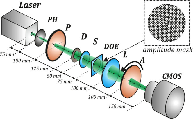
Experimental optical setup. The solid-state laser has an output wavelength λ = 532 nm, PH is a pinhole (100-μm aperture), P is a polarizer, D is a diaphragm, S is an S-waveplate (radial polarization converter), DOE is an amplitude diffractive optical element forming a superposition of eight vortex beams with orders of ±1, ±2, ±3, and ±4, L is a lens with a focal length f = 150 mm, A is an analyser, and CMOS is a CMOS-video camera (LOMO TC-1000, 3664×2740 pixel resolution).
The inset in Fig. 4 shows the amplitude transmission function for the diffractive optical element. An amplitude mask is obtained by encoding45 the transmission function of the multi-order vortex DOE:
| 13 |
where n is an index of diffractive order, m n is the topological charge of the vortex beam, and (u n, v n) are the carrier spatial frequencies.
The operating principle this DOE is shown in Fig. 5. The effect is the introduction of optical vortices of different orders in a radially polarized Gaussian beam, which initially does not have a vortex phase. Using a multi-order DOE, multiple optical vortices of different orders are formed, which allows the simultaneous measurement of the degree of polarization conversion at each spot.
Figure 5.
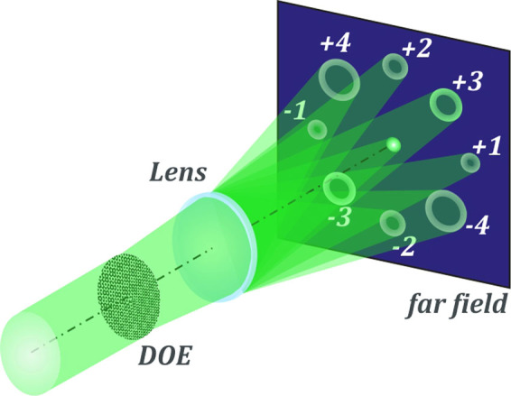
Operating principle of a multi-order vortex diffractive optical element.
The diffraction pattern formed by the amplitude diffractive optical element is shown in Fig. 6. Figure 6a shows the simulated intensity distribution generated by the DOE. Because we utilized an amplitude DOE, the intensity of the zero diffraction order is too high in comparison with the intensity from the other diffraction orders. To clearly see the non-zero diffraction orders, we removed the zero diffraction order from the simulated picture. Figure 6b shows the intensity distributions obtained without the analyser. These experimentally obtained distributions show simultaneous interaction with eight optical vortices of different orders. Each of them is formed with a separate diffraction order at the corresponding location in the focal plane. In the paraxial case considered here, the displacement of the diffraction orders from the centre of the focal plane has no effect on polarization conversion. To confirm the order of the vortices, we recorded the interference pattern of the vortices with the Gaussian beam, resulting in characteristic fork fringes, as shown in Fig. 6c. The interference patterns confirm the order of the vortices to be m = ±1, ±2, ±3, and ±4, respectively.
Figure 6.
Diffraction pattern formed in the far-field region when passing the laser beam through the amplitude diffractive optical element, generating a superposition of eight vortex beams. (a) Simulation and (b) experimental result. (c) Experimentally obtained interference patterns of the generated vortex beams.
Intensity distributions obtained with different orientations of the analyser are shown in Fig. 7. The analyser rotation angles are equal to ±45 and 90 degrees. The analyser orientation in these figures is represented by white arrows. In addition, the zero diffraction order, in which a laser beam has a topological charge of m = 0, gives an indication of the orientation of the analyser. As was predicted theoretically, in the case of optical vortices with m = ±2, ±3, and ±4 the conversion of radially polarized light into azimuthally polarized light is observed. For optical vortices with m = ±1, no conversion is observed. Figure 8 shows the intensity distributions formed in the far-field region using a diffractive optical element forming two vortex beams with topological charge m = ±10. It can be clearly observed that in this case, we obtain a laser beam with a nearly perfect azimuthal polarization, while the radial component decreases significantly. Thus, the experimental results are in good agreement with the simulation results presented above.
Figure 7.
Diffraction pattern formed in the far-field region when passing the laser beam through the amplitude diffractive optical element, generating a superposition of eight vortex beams for different orientations of the analyser. (a) 0, (b) +45, (c) −45, and (d) 90 degrees.
Figure 8.
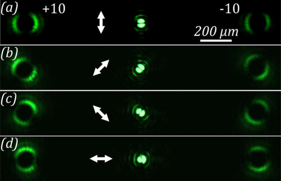
Diffraction pattern formed in the near-field region when passing the laser beam through the amplitude diffractive optical element, generating vortex beams with a topological charge m = ±10 for different orientations of the analyzer. (a) 0, (b) +45, (c) −45, and (d) 90 degrees.
Discussion
We conducted a theoretical analysis of the effect of sharply focusing a cylindrically polarized beam in the presence of an optical element with a vortex phase. Analytical expressions for the field in the focal region for radially and azimuthally polarized beams were obtained. In this way, we demonstrated the conversion of polarization state in cylindrically polarized laser beams by introducing a higher-order vortex phase singularity. In addition, a numerical study was performed. The experimental results are in good agreement with the simulation.
Our theoretical and experimental results show that increasing the order of the phase singularity leads to increased conversation of the radially polarized laser beam into an azimuthally polarized one. Our results demonstrate the close connection between of the polarization and phase states of electromagnetic beams. Specific combinations of the polarization and spatial properties of the laser beam are important for certain applications, such as telecommunication and materials processing. Bozinovic et al.27 presented multiplexing techniques that use the wavelength, amplitude, phase, and polarization of light to encode information. Taking into account the results presented here, it is necessary to use combinations of orthogonal polarization states and orbital angular momentum carefully. On the other hand, the effect of a phase vortex on the cylindrical polarization shown in our work will allow for a better understanding of the processes occurring during the interaction of laser radiation with matter, as in ablation23.
Methods
Model of focusing cylindrically polarized beams
In the Debye approximation of tight focusing, the cylindrical components of the electric field of a monochromatic electromagnetic wave are described by the following expression31:
| 14 |
where (ρ, φ, z) are the cylindrical coordinates in the focal region, (θ, ϕ) are the spherical angular coordinates of the focusing system’s output pupil, α is the maximum value of the azimuthal angle related to the system’s numerical aperture, B(θ, ϕ) is the transmission function, T(θ) is the pupil’s apodization function (equal to for aplanatic systems), is the wavenumber, λ is the wavelength, f is the focal length, c r(ϕ), c ϕ(ϕ) are the polarization coefficients of the incident radiation.
For vortex beams , Eq. (14) can be simplified as follows:
| 15 |
where the components of vector Q m(ρ, φ, θ) have a definite form for each specific polarization and are superpositions of the Bessel functions of different orders31, 37.
When interacting with a vortex phase, the azimuthal and radial polarization are of particular interest12. The expressions of Q m(ρ, φ, θ) for the corresponding polarization types are given below:
| 16 |
| 17 |
As observed from Eq. (16) and Eq. (17), the azimuthal polarization is the easiest to calculate because, in this case, only the transverse components of the field are nonzero.
Acknowledgements
This work was financially supported by the Russian Foundation of Basic Research (RFBR) (16-07-00825, 16-37-00241, 16-29-11698, 16-29-11744, 14-07-00177).
Author Contributions
A.P.P. and S.N.K designed the research; A.P.P. conducted the experiments. All authors discussed the results, analyzed data, wrote the manuscipt and reviewed the manuscript.
Competing Interests
The authors declare no competing financial interests.
Footnotes
Alexey Petrovich Porfirev, Andrey Ustinov and Svetlana N. Khonina contributed equally to this work.
Publisher's note: Springer Nature remains neutral with regard to jurisdictional claims in published maps and institutional affiliations.
References
- 1.Nye JF, Berry MV. Dislocations in wave trains. Proc. R. Soc. London, Ser. A. 1974;336:165–190. doi: 10.1098/rspa.1974.0012. [DOI] [Google Scholar]
- 2.Soskin MS, Vasnetov MV. Dsingular optics. Progress in Optics. 2001;42:219–276. doi: 10.1016/S0079-6638(01)80018-4. [DOI] [Google Scholar]
- 3.Berry MV, Dennis MR. Polarization singularities in isotropic random vector waves. Proc. R. Soc. London, Ser. A. 2001;457:141–155. doi: 10.1098/rspa.2000.0660. [DOI] [Google Scholar]
- 4.Dennis MR, O’Holleran K, Padgett MJ. Singular optics: Optical vortices and polarization singularities. Progress in Optics. 2009;53:293–363. doi: 10.1016/S0079-6638(08)00205-9. [DOI] [Google Scholar]
- 5.Poynting J. The wave motion of a revolving shaft, and a suggestion as to the angular momentum in a beam of circularly polarised light. Proc. R. Soc. London, Ser. A. 1909;82:560–567. doi: 10.1098/rspa.1909.0060. [DOI] [Google Scholar]
- 6.Beth R. Mechanical detection and measurement of the angular momentum of light. Phys. Rev. 1936;50:115–125. doi: 10.1103/PhysRev.50.115. [DOI] [Google Scholar]
- 7.Holbourn AHS, Berry MV. Angular momentum of circularly polarized light. Nature. 1936;137:31. doi: 10.1038/137031a0. [DOI] [Google Scholar]
- 8.Allen L, Barnett SM, Padgett M. Optical Angular Momentum. London: Institute of Physics Publishing; 2003. [Google Scholar]
- 9.Hasman E, Biener G, Niv A, Kleiner V. Space-variant polarization manipulation. Progress in Optics. 2005;47:215–289. doi: 10.1016/S0079-6638(05)47004-3. [DOI] [PubMed] [Google Scholar]
- 10.Molina-Terriza G, Torres JP, Torner L. Twisted photons. Nat. Phys. 2007;3:305–310. doi: 10.1038/nphys607. [DOI] [Google Scholar]
- 11.Franke-Arnold S, Allen L, Padgett M. Advances in optical angular momentum. Laser Photonics Rev. 2008;2:299–313. doi: 10.1002/lpor.200810007. [DOI] [Google Scholar]
- 12.Zhan Q. Cylindrical vector beams: from mathematical concepts to applications. Adv. in Opt. Photon. 2009;1:1–57. doi: 10.1364/AOP.1.000001. [DOI] [Google Scholar]
- 13.Yao AM, Padgett MJ. Orbital angular momentum: origins, behavior and applications. Adv. Opt. Photon. 2011;3:161–204. doi: 10.1364/AOP.3.000161. [DOI] [Google Scholar]
- 14.Andrews DL, Babiker M. The Angular Momentum of Light. Cambridge, England: Cambridge University Press; 2013. [Google Scholar]
- 15.Simpson NB, Dholakia K, Allen L, Padgett MJ. Mechanical equivalence of spin and orbital angular momentum of light: an optical spanner. Opt. Lett. 1997;22:52–54. doi: 10.1364/OL.22.000052. [DOI] [PubMed] [Google Scholar]
- 16.Grier DG. A revolution in optical manipulation. Nature. 2003;424:810–816. doi: 10.1038/nature01935. [DOI] [PubMed] [Google Scholar]
- 17.Soifer VA, Kotlyar VV, Khonina SN. Optical microparticle manipulation: advances and new possibilities created by diffractive optics. Phys. Part. Nucl. 2004;35:733–766. [Google Scholar]
- 18.Hell SW, Wichmann J. Breaking the diffraction resolutionlimit by stimulated-emission-depletion fluorescence microscopy. Opt. Lett. 1994;19:780–782. doi: 10.1364/OL.19.000780. [DOI] [PubMed] [Google Scholar]
- 19.Biss DP, Youngworth KS, Brown TG. Dark field imaging with cylindrical-vector beams. Appl. Opt. 2006;45:470–479. doi: 10.1364/AO.45.000470. [DOI] [PubMed] [Google Scholar]
- 20.Khonina SN, Golub I. How low can sted go? comparison of different write-erase beam combinations for stimulated emission depletion microscopy. J. Opt. Soc. Am. A. 2012;29:2242–2246. doi: 10.1364/JOSAA.29.002242. [DOI] [PubMed] [Google Scholar]
- 21.Hamazaki J, et al. Optical-vortex laser ablation. Opt. Express. 2010;18:2144–2151. doi: 10.1364/OE.18.002144. [DOI] [PubMed] [Google Scholar]
- 22.Kraus M, et al. Microdrilling in steel using ultrashort pulsed laser beams with radial and azimuthal polarization. Opt. Express. 2010;18:22305–22313. doi: 10.1364/OE.18.022305. [DOI] [PubMed] [Google Scholar]
- 23.Hnatovsky C, Shvedov VG, Shostka N, Rode AV, Krolikowski W. Polarization-dependent ablation of silicon using tightly focused femtosecond laser vortex pulses. Opt. Lett. 2012;37:226–228. doi: 10.1364/OL.37.000226. [DOI] [PubMed] [Google Scholar]
- 24.Allegre OJ, Perrie W, Edwardson SP, Dearden G, Watkins KG. Laser microprocessing of steel with radially and azimuthally polarized femtosecond vortex pulses. J. Opt. 1974;085601:2012. [Google Scholar]
- 25.Gibson G, et al. Free-space information transfer using light beams carrying orbital angular momentum. Opt. Express. 2004;12:5448–5456. doi: 10.1364/OPEX.12.005448. [DOI] [PubMed] [Google Scholar]
- 26.Wang J, et al. Terabit free-space data transmission employing orbital angular momentum multiplexing. Nat. Photonics. 2012;6:488–496. doi: 10.1038/nphoton.2012.138. [DOI] [Google Scholar]
- 27.Bozinovic N, et al. Terabit-scale orbital angular momentum mode division multiplexing in fibers. Science. 2013;340:1545–1548. doi: 10.1126/science.1237861. [DOI] [PubMed] [Google Scholar]
- 28.Hasegawa S, Hayasaki Polarization distribution control of parallel femtosecond pulses with spatial light modulators. Opt. Express. 2013;21:12987–12995. doi: 10.1364/OE.21.012987. [DOI] [PubMed] [Google Scholar]
- 29.Zhao Y, Edgar JS, Jeffries GDM, McGloin D, Chiu DT. Spin-to-orbital angular momentum conversion in a strongly focused optical beam. Phys. Rev. Lett. 2007;99:073901. doi: 10.1103/PhysRevLett.99.073901. [DOI] [PubMed] [Google Scholar]
- 30.Sheppard CJR, Gong W, Si K. Polarization effects in 4pi microscopy. Micron. 2011;42:353–359. doi: 10.1016/j.micron.2010.07.013. [DOI] [PubMed] [Google Scholar]
- 31.Khonina SN, Ustinov AV, Volotovsky SG. Shaping of spherical light intensity based on the interference of tightly focused beams with different polarizations. Opt. Laser Technol. 2014;60:99. doi: 10.1016/j.optlastec.2014.01.012. [DOI] [Google Scholar]
- 32.Ciattoni A, Cincotti G, Palma C. Circularly polarized beams and vortex generation in uniaxial media. J. Opt. Soc. Am. A. 2003;20:163–171. doi: 10.1364/JOSAA.20.000163. [DOI] [PubMed] [Google Scholar]
- 33.Marrucci L, Manzo C, Paparo D. Optical spin-to-orbital angular momentum conversion in inhomogeneous anisotropic media. Phys. Rev. Lett. 2006;96:163905. doi: 10.1103/PhysRevLett.96.163905. [DOI] [PubMed] [Google Scholar]
- 34.Fadeyeva TA, et al. Spatially engineered polarization states and optical vortices in uniaxial crystals. Opt. Express. 2010;18:10848–10863. doi: 10.1364/OE.18.010848. [DOI] [PubMed] [Google Scholar]
- 35.Khonina SN, Karpeev SV, Alferov SV, Soifer VA. Generation of cylindrical vector beams of high orders using uniaxial crystals. J. Opt. 2015;17:065001. doi: 10.1088/2040-8978/17/6/065001. [DOI] [Google Scholar]
- 36.Moreno I, Davis JA, Ruiz I, Cottrell DM. Decomposition of radially and azimuthally polarized beams using a circular-polarization and vortex-sensing diffraction grating. Opt. Express. 2007;18:7173–7183. doi: 10.1364/OE.18.007173. [DOI] [PubMed] [Google Scholar]
- 37.Khonina SN, Savelyev SD, Kazanskiy NL. Vortex phase elements as detectors of polarization state. Opt. Express. 2015;23:17845–17859. doi: 10.1364/OE.23.017845. [DOI] [PubMed] [Google Scholar]
- 38.Cardano F, et al. Polarization pattern of vector vortex beams generated by q-plates with different topological charges. Appl. Opt. 2012;51:C1–C6. doi: 10.1364/AO.51.0000C1. [DOI] [PubMed] [Google Scholar]
- 39.Yi X, et al. Generation of cylindrical vector vortex beams by two cascaded metasurfaces. Opt. Express. 2014;22:17207–17215. doi: 10.1364/OE.22.017207. [DOI] [PubMed] [Google Scholar]
- 40.Nesterov AV, Niziev VG. Propagation features of beams with axially symmetric polarization. J. Opt. B: Quantum Semiclass. Opt. 2001;3:S215–S219. doi: 10.1088/1464-4266/3/2/372. [DOI] [Google Scholar]
- 41.Richards B, Wolf E. Electromagnetic diffraction in optical systems ii. structure of the image field in an aplanatic system. Proc. R. Soc. Lond. A Math. Phys. Sci. 1959;253:358–379. doi: 10.1098/rspa.1959.0200. [DOI] [Google Scholar]
- 42.Khonina SN, Kazanskiy NL, Volotovsky SG. Vortex phase transmission function as a factor to reduce the focal spot of high-aperture focusing system. J. Mod. Opt. 2011;58:748–760. doi: 10.1080/09500340.2011.568710. [DOI] [Google Scholar]
- 43.Prudnikov AP, Brychkov YA, Marichev OI. Integrals and Series: Special Functions. Moscow: Nauka Publisher; 1983. [Google Scholar]
- 44.Beresna M, Gecevicius M, Kazansky PG, Gertus T. Radially polarized optical vortex converter created by femtosecond laser nanostructuring of glass. Appl. Phys. Lett. 2011;98:201101. doi: 10.1063/1.3590716. [DOI] [Google Scholar]
- 45.Soifer VA. Methods for computer design of diffractive optical elements. New Jersey: Wiley-Interscience; 2002. [Google Scholar]


