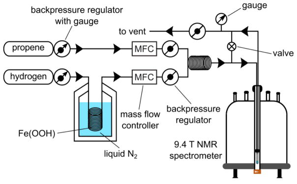
Figure 2.
The diagram of the experimental setup. In continuous-flow experiment, both gas flows are operating and enable continuous simultaneous loading of propene and p-H2 through the catalyst solution placed in the NMR tube. Normal ultra-high purity (>99.999%) hydrogen gas passes through Fe(OOH) catalyst at liquid N2 temperature (~77K) or utilizes a p-H2 generator using cryo-cooling (and producing ~80% p-H2). Both gas flows are controlled by the mass flow controllers (MFC), and the system pressure is regulated by the safety valve (labeled as ø set to ~7.1 atm) immediately before the vent. Manual valve (⊗) enables fast (in less than 1 s) cessation of gas flow through solution placed in the NMR tube. In batch-mode production method, propene gas is loaded in the solution first, and it is followed by hydrogen gas flow only. Hydrogenation is performed inside 9.4 T spectrometer under PASADENA condition[19] and in the Earth’s magnetic field under ALTADENA[4b] condition respectively.

