Abstract
Transcatheter aortic valve implantation (TAVI) was initially proven as an alternative to valve replacement therapy in those beyond established risk thresholds for conventional surgery. With time the technique has been methodically refined and offered to a progressively lower risk cohort, and with this evolution has come that of the significant imaging requirements of valve implantation. This review discusses the role of transoesophageal echocardiography (TOE) in the current TAVI arena, aligning it with that of cardiac computed tomography, and outlining how TOE can be used most effectively both prior to and during TAVI in order to optimise outcomes.
Keywords: 3D transoesophageal echo, aortic stenosis, transcatheter aortic valve implantation
Background
After the introduction of transcatheter aortic valve implantation (TAVI) has come the requisite debate as to how best to approach the imaging requirements of this technique. Performed via minimally invasive approaches without direct surgical visualisation of the valve, TAVI has on occasion been cited as a ‘blind’ procedure. As a consequence, the accurate determination of the size of the intended implant is almost wholly dependent on robust pre-procedural imaging. Annular measurements are of particular importance in the TAVI arena as the consequences of either over or underestimating the size of the required implant can lead to device embolisation, significant paravalvular regurgitation, root rupture and conduction disturbances. Transthoracic echocardiography (TTE), transoesophageal echocardiography (TOE), multi-detector computed tomography (MDCT) and magnetic resonance imaging (MRI) have been extensively studied with respect to pre-procedural aortic annular sizing, and at present, MDCT is both more frequently used and more often cited as the gold standard. This review will examine the merits of TOE in this arena and will provide a step-by-step guide as to how to optimise aortic annular sizing using this modality.
Aortic annular anatomy and implications for the imager
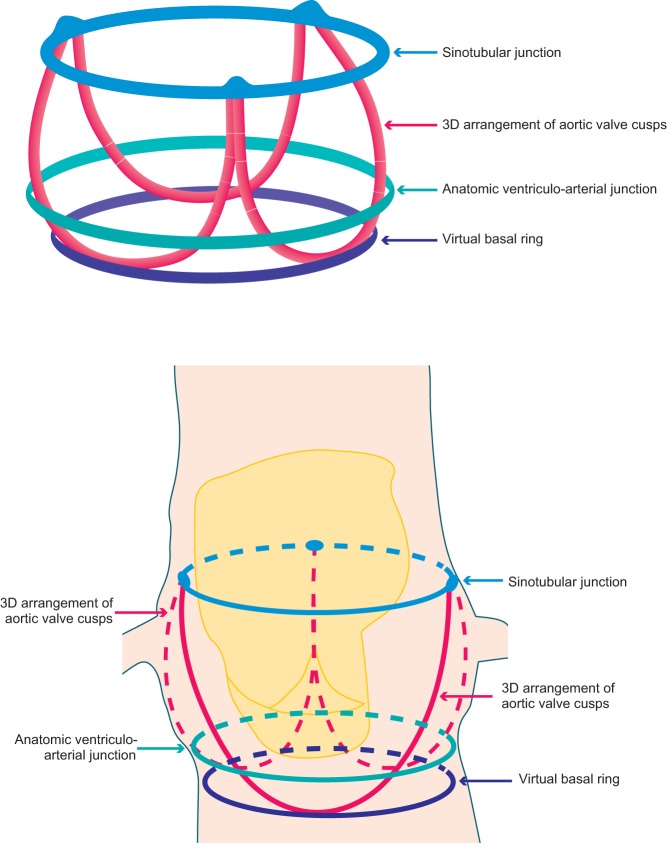
Unlike the mitral valve that has a well-defined anatomical annulus lending itself to analysis, the aortic valve annulus lacks such a distinct geometrical profile. It is therefore important to realise that when referring to the aortic valve, the term ‘annulus’ refers to a virtual plane at the level of basal attachments of the valve cusps (Fig. 1). As such this is not a true annulus but rather a representation of the geometrical best fit at this position. There has been some recent debate concerning this virtual annulus and the appropriateness of its use in valve sizing. With emerging evidence that it is in fact a 3D structure, there is some inference that the basal virtual ring that is universally used for valve sizing may in reality significantly underestimate the actual annulus with potential implications for the device landing zone (1). However, for now, the annulus that is measured by all imaging techniques prior to TAVI is the narrowest part of the aortic root, composed of a virtual ring with three anchor points at the base of each of the attachments of the aortic valve leaflets (2).
Figure 1.
Depiction of the anatomical arrangement of the aortic valve apparatus including the virtual basal ring.
Despite historically being labelled as circular, the design of the assumed annulus is much more complex than this, and in reality, is ovoid rather than spherical. It is the long axis aortic view that represents the shortest diameter of this oval, making the sizing of this structure for the implantation of a circular valve fraught with potential error if these measurements were to be taken with 2D imaging. For these reasons, 2D analysis in this arena has now been superseded by 3D imaging, which more accurately delineates non-circular anatomy. This is of particular importance in the TAVI population as with increasing age and hypertension, the aortic annulus becomes progressively less spherical and assumes an increasingly elliptical profile. The progressively oval form of the annulus in aortic stenosis has been comprehensively described in a recent study comparing its profile in those with severe aortic stenosis compared with a normal cohort (3). This study concluded that the LVOT becomes less distensible and undergoes remodeling in severe AS leading to its increasingly ovoid shape. This is not only of critical importance to the imager but also has implications for the assessment of aortic stenosis severity by traditional equations that assume LVOT circularity.
Additionally, as the geometry of the aortic apparatus changes throughout the cardiac cycle, it is important to standardise the phase in which measurements are acquired. Annular measurements performed by echocardiography are made during mid-systole when root dimensions are maximal and most circular (4). This approach is logical as post-deployment of a transcatheter heart valve (THV), 86% of balloon-expandable valves are circular at the central coaptation point (5), with half of self-expanding valves showing this circularity (6). MDCT on the other hand will size at any point in the cardiac cycle depending on when the optimal image is obtained, (7) although as yet this has not been shown to be a cause of significant error.
These changes in the profile of the annulus during the cardiac cycle have generated debate regarding which measure, area or perimeter, most accurately reflects annular sizing regardless of cyclical effects. Proponents exist of both measures, with one recent study demonstrating equitable predictive value for more than mild paravalvular regurgitation (PVR) with the use of either area or perimeter annular measurements (8). However, it is perimeter sizing that is most often adhered to in manufacturer’s sizing charts (Table 1) and offers a logical advantage over area calculation. Area measurements are subject to potentially greater error with increasing annular elongation. As the annulus becomes progressively more ovoid, the area reduces disproportionately to the perimeter leading to potential underestimation of annular size (9). After many years’ experience in valve sizing and with careful consideration of the previously mentioned dialogue, it is the practice in our centre to use perimeter-derived measurements for the sizing of the annulus. We have found this method to correlate well with manufacturer sizing charts and perform robustly in predicting accurate valve implant size (10). Although the potential difficulties involved in implanting a circular device into an oval annulus are obvious, it is important to realise that the shape of the annulus is not the only determinant of valve sizing. In fact, each component of aortic complex including sino-tubular junction, aortic sinuses, LVOT (septal bulge and the extent and position of calcification) as well as coronary ostia height are important factors in determining what type and size of valve is appropriate (8).
Table 1.
Sizing charts for use in common percutaneous aortic valve implants.
| CoreValve | Evolute R | Sapien 3* | |
|---|---|---|---|
| Valve sizes (mm) | 26, 29, 31 | 23, 26, 29 | 23, 26, 29 |
| Aortic annulus dimension (mm) | 20–23 (26) | 18–20 (23) | 18–22 (23) |
| 23–27 (29) | 20–23 (26) | 21–25 (26) | |
| 26–29 (31) | 23–26 (29) | 24–28 (29) | |
| Sheath size (Fr) | 18 | 14 | 14,16 |
| Annulus area (mm2) | 314.2–415.5 | 254.5–314.2 | 338–430 (23) |
| 415.5–572.6 | 314.2–415.5 | 430–546 (26) | |
| 530.9–660.5 | 415.5–572.6 | 540–680 (29) | |
| Annulus perimeter (mm) | 62.8–72.3 | 56.5–62.8 | ** |
| 72.3–84.8 | 62.8–72.3 | ||
| 81.7–91.1 | 72.3–84.8 |
Measurements based on MDCT. **Perimeter-based sizing for the Sapien 3 valve is currently in development.
The intentional oversizing of implants is a recognised strategy to reduce the risk of PVR (11); however, inadvertent oversizing or undersizing can negatively influence outcomes. Unintentional oversizing increases the risk of rupture of the root, significant conduction disturbances and device underexpansion, whereas unintentional undersizing conveys an elevated risk of clinically significant PVR and device embolization (2, 5). PVR is still the most frequent complication of implanting a transcatheter heart valve (THV) with up to 10% of cases exhibiting moderate or severe PVR (1) and as high as 18% when significant left ventricular outflow tract (LVOT) calcification is present (12). Moderate or severe PVR is an independent predictor of mortality after THV implant (2), and therefore, the temptation may be to err on the side of a larger implant; however, it is worth noting that upsizing from a 23 mm to a 26 mm prosthesis is associated with a 28% increase in external valve area (13). Adherence to the manufacturer sizing charts of these valves has been recently validated in a study of 1023 patients demonstrating lower rates of PVR if the supplied charts are followed (14). Following on from the previous discussion, it is worth mentioning that these measurements were perimeter derived rather than area derived.
Peri-procedural and general considerations in the use of TOE and MDCT
Although not the primary focus of this review, it is worth mentioning the peri-procedural use of TOE. Real-time imaging guidance throughout implantation offers instantaneous diagnosis of complications, as well as enhanced understanding of the most appropriate landing zone (15). Accurate positioning is of immense importance; a device that is positioned too low may more frequently result in aortic regurgitation, atrioventricular node impingement or mitral apparatus interference with subsequent often poorly tolerated mitral regurgitation. Equally, a high deployment may occlude the coronary ostia resulting in coronary ischaemia, may cause aortic injury and the device may migrate or embolise (15).
As already mentioned, PVR is of particular concern given its impact on post-procedural outcomes, with valve under-expansion identified as the predominant cause (44%) in the UK TAVI registry, followed by low valve positioning (22.2%) and high sitting implants (5.5%) (16). The availability of TOE during the implant procedure undoubtedly offers diagnostic and repositioning advantages in the setting of an unexpectedly significant degree of PVR, offering real-time diagnosis and avoiding delays in management. In our centre, we not only benefit from procedural TOE guidance for complication surveillance but also to guide implantation of the valve using the EchoNavigator technology. This fusion technology allows real-time overlay of 3D TOE onto fluoroscopy images, providing dual-modality guidance of device positioning, with an additional aim of supporting zero-contrast implantation procedures.
The issue of contrast in general is a much-debated area in both interventional and imaging fields, particularly in the TAVI arena, which is more typically comprises an older cohort with comorbid considerations often including chronic kidney disease. Although there is currently no consensus regarding the degree of threat posed by contrast-induced acute kidney injury (CIAKI), there is an increasing understanding that lower baseline estimated glomerular filtration rate (eGFR) and hydration status are potentially the most relevant predictors of this complication (17, 18). It is certainly a factor to be considered in the use of pre-procedural contrast-enhanced MDCT; however, the ability of MDCT to delineate the access anatomy, including the site and degree of any significant calcification, and to provide accurate aortic dimensions is an invaluable procedural planning aid. The suitability of peripheral access vessels to accommodate relatively large sheaths is vital in deciding the most appropriate implant route, and MDCT is able to identify potential points along the line of travel of the intended implant at which it simply might not fit (19). Furthermore, in an attempt to subsequently limit contrast administration during valve implantation, MDCT offers the ability to reconstruct suitable fluoroscopic angles for valve deployment, thereby potentially reducing the dose of contrast from repeated attempts to obtain the optimal angle peri-procedurally (20). However, peri-procedure 3D transoesophageal echo, in combination with fluoroscopy fusion imaging (EchoNavigator), can also be used to determine the appropriate fluoroscopy plane for valve deployment, and we have successfully performed several TAVI procedure with zero contrast using this approach.
However, what pre-procedural TOE imaging adds to that provided by MDCT is the encompassment of whole heart function, in particular, LV performance and the assessment of concomitant valve disease. It is of particular interest and importance to define the degree and cause of any co-existing mitral regurgitation. The prevalence of those with at least moderate mitral regurgitation undergoing TAVI can be up to 33% (21), with an increased mortality associated with this. However, in those with functional MR not due to intrinsic valve or apparatus disease, the majority experience a significant improvement in the degree of MR after TAVI (21, 22). Alternatively, a very large mitral annulus (>35.5 mm), calcification of the mitral apparatus and intrinsic valve leaflet dysfunction have been reported as independent predictors of persistent MR after TAVI (22). Therefore, the ability to identify mitral pathology pre-procedurally may help guide decisions regarding the appropriateness of THV implantation as opposed to open surgical treatment of both the aortic and mitral dysfunction.
The great debate
With all the above considerations in mind regarding the use of each modality in the planning and delivery of aortic implantation comes the requisite debate on the appropriate sizing of these implants. Given the complexity of the aortic annulus, the difficulties in measuring it accurately non-invasively become obvious. As discussed earlier, it is now accepted that 2D echocardiography (including TOE) will not accurately account for the elliptical geometry of the annulus and often underestimates the annulus diameter (23). In addition, although 2D TOE can often define the annular–ostial distance for the right coronary artery, the left main stem ostium usually lies in the coronal plane that cannot be acquired by standard 2D imaging (24). This is important as 3D TOE can not only measure the distance from annulus to LMS ostium but also can determine the length of the left coronary cusp which, if beyond a critical length, can occlude the LMS ostium after valve deployment. 3D TOE has been evaluated in head-to-head comparisons with MDCT with each technique offering potential advantages; 3D TOE demonstrates excellent temporal resolution, provides simultaneous physiological assessment, enables visualization of the hinge points and adjacent structures and does not suffer from motion artefact; however, it demonstrates poor lateral resolution and is subject to blooming artefact. MDCT on the other hand undoubtedly benefits from superior tissue lumen contrast, better lateral resolution and provides assessment of peripheral arteries. There have certainly been a number of studies demonstrating a clinically significant difference between measurements obtained by each modality, with TOE often returning smaller sizing estimates than MDCT (5, 25, 26). A small but notable study by Ng and coworkers (5) found the annular underestimate by 3D TOE to be up to 9.6% compared to MDCT in 53 participants. However, the absolute difference was small and can likely be at least in part attributed to the lower spatial resolution of 3D TOE at that time.
However, even with some of the evidence returning a discrepancy in annular measurements between techniques, the literature to date does not clarify whether TOE undersizes inappropriately or appropriately with respect to MDCT. In a recent study, 29.5% of patients would have been deemed ineligible for TAVI because of overestimation of annular measurements by MDCT, a figure reduced to 1.3% with the use of TOE (27). This idea that the annulus is sized larger with MDCT was inadvertently highlighted in a paper that argued that undersizing with TOE was likely to have such significant clinical influence that it should only be used when MDCT was unavailable. However, a significant number (13.5%) of the group sized with MDCT in the study underwent a THV with an underfilled deployment balloon, hinting at concerns regarding potential oversizing in the MDCT cohort (Binder, JACC, 2013).
In contrast with these reports of sizing discrepancies, there have been a number of trials reporting good correlation between 3D TOE and MDCT for annular sizing (28, 29, 30), together with evidence of equivalence between MDCT and 3D TOE in predicting moderate or severe PVR, an important potential complication of THV implantation (13, 31, 32). In a recent small retrospective study (29), TOE, MDCT and MRI all performed comparatively well with surgical device sizing, whereas a larger trial demonstrated good concordance in measurements for both area and perimeter between 3D TOE, MDCT and angiography (28). Tsang and coworkers compared all three modalities (3D TOE, MDCT and CMR) for comparison of sizing in both calcium-containing rings and ex vivo heart models (25). MDCT tended to overestimate annular size compared with CMR, whereas 3D TOE tended to underestimate, the difference was greater for area than that for perimeter measures. Understandably, the reproducibility of both modalities fell with increasing calcium burden, and it should also be noted that these results were obtained from a non-beating heart model, thereby eliminating some of the intrinsic difficulties of sizing during the cardiac cycle. Furthermore, a recent trial (8) investigated the off-label use of commercially available 3D TOE software for mitral valve assessment in 100 participants undergoing TAVI compared with retrospective MDCT (320 slice) analysis of the aortic annular measurements. The echo system performed well with measurements closely approximated to those obtained by MDCT with a non-significant difference in the receiver-operating characteristic for both area and perimeter measures (<1% difference). More than mild PVR was predicted by both modalities in this study with equivalent accuracy.
In debating this evidence it is of course worth noting that the modality that tends to return measurements in between those obtained by either TOE or MDCT is MRI (25); however, this technique does not seem to be extensively used for this purpose in daily practice, likely due to financial and logistical constraints in many centres. The current consignment of European and American guidelines (24) state that there is no consensus regarding the sought after gold standard for imaging in this area, and the use of 3D TOE is recommended for aortic annular sizing along with MDCT. The authors of this review are of the opinion that 3D TOE is appropriate for the sizing of percutaneous aortic implants when performed in a centre with sufficient experience in this technique.
What does the future hold?
As for the future of 3D echocardiography in interventional valve therapy, it is likely that automated platforms will supersede the current dependence on manual outlining of the annular dimensions. A promising version of reconstruction software that generates a geometric model of the aortic root from 3D TOE images and then performs quantitative analysis of these structures has been validated in a small pilot study against both standard 3D TOE and MDCT (33). There is also emerging computational modelling software that predicts the in vivo morphology of the implanted valve via finite element computer simulation. This technology has been successfully applied to a MDCT model where it was able to accurately predict both frame morphology and calcium displacement after valve deployment (34). It seems inevitable that this type of automated valve modelling software will be applied to 3D echocardiography in the near future, potentially streamlining the process of annular analysis.
Summary
Considering all of the above, the labelling of CT as the gold standard in in the aortic annular sizing arena seems rather injudicious on the basis of varied evidence. As with all modalities, 3D TOE performs sufficiently robustly in high-volume centres with expertise in its acquisition and application.
For those with an interest in how the acquisition and analysis of 3D TOE should be undertaken, a stepwise approach is presented below.
Stepwise approach to aortic annular sizing prior to TAVI
The first step in this process is to optimise the 2D TOE image with the aortic valve laid out in the sagittal view, usually 120–140°, which is familiar as the long-axis view. Once the 2D image has been optimised, the 3D zoom function is selected and the lateral and elevation widths customised to include the entirety of the LVOT and aortic root, taking care to include the sino-tubular junction. This 3D image is then acquired for post-processing on commercially available software. As measurements will be performed on a static image, the focus should remain on optimising the spatial rather than temporal resolution, being mindful of the necessary trade-off between frame rate and line density. For example, if image acquisition is via a Philips system, the use of the high-volume rate 3D acquisition function is not recommended as it enhances temporal resolution at the expense of the more important spatial resolution. The steps below outline the process in more detail.
Open the 3D analysis software package. The displayed image will be seen in four sections (sagittal, coronal, transverse and a full volume render). Select the mid-systolic frame (Table 2).
Align the sagittal and coronal planes to bisect the long-axis of the aortic valve (Table 2).
It is then necessary to align the transverse plane at the level of the annulus, at the most caudal attachment of the three cusps (the hinge point). In this case, the red line representing the transverse view is moved such that it crosses the hinge point of the right coronary cusp in the sagittal view (red arrow) and left (blue arrow) and non-coronary cusp (yellow arrow) in coronal view (Table 2). By rotating the orthogonal plane of the transverse view, it is important to ensure that the annulus to be measured falls below the hinge points and does not include any caudal aspect of the cusps as this may interfere with accurate measurements. Table 2 demonstrate how rotating the blue plane will help in assuring that the transverse view is bisecting the hinge point at the level of the non- and left-coronary cusps.
Select the transverse plane image from this dataset (Table 2).
Trace the circumference and area of the annulus by pointing and clicking in an iterative manner around it. This is done in a similar manner to CT, using the inner edge of the annulus, ignoring any soft low-intensity echoes and irregular bright (calcium) indentations, which are traced through.
Once the annulus has been measured, it is possible to identify the ostium of the left main coronary artery and measure the distance between this and the base of the left-coronary cusp (any measurement below 11 mm is considered too small to accommodate valve expansion without significant risk of coronary ostial occlusion). The figures below outline this process (Table 2). Firstly, align the sagittal and coronal planes to bisect the long-axis of the aortic valve. The red marker line on the sagittal plane is then advanced cranially along the aortic root until the origin of the left main stem (LMS) is identified as an indentation at roughly the 10 O’clock position of the transverse image. The green marker of the transvers image is then rotated anticlockwise until it is aligned with the LMS ostium. The distance from the base of the left-coronary cusp to the ostium can then be measured as shown by the yellow marker.
Table 2.
Step-wise approach to aortic annular sizing prior to TAVI.
1. Open the 3D analysis software package. The displayed image will be seen in four sections (sagittal, coronal, transverse and a full volume render). Select the mid-systolic frame. Note that the image in the right upper panel is a mirror image: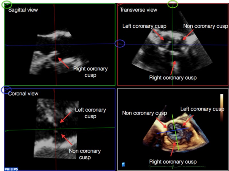
|
2. Align the sagittal and coronal planes to bisect the long-axis of the aortic valve: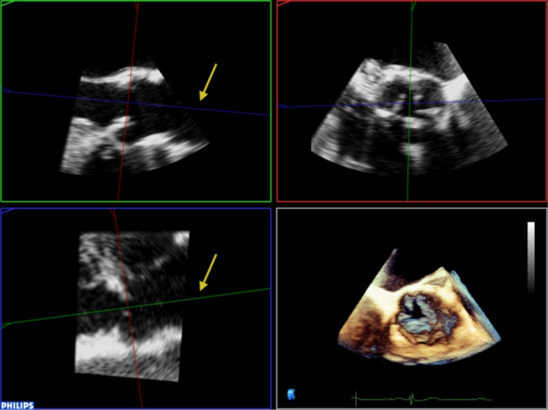
|
3. It is then necessary to align the transverse plane at the level of the annulus, at the most caudal attachment of the three cusps (the hinge point). In this case, the red line representing the transverse view is moved such that it crosses the hinge point of the right coronary cusp in the sagittal view (red arrow) and left (blue arrow) and non-coronary cusp (yellow arrow) in coronal view. By rotating the orthogonal plane of the transverse view, it is important to ensure that the annulus to be measured falls below the hinge points and does not include any caudal aspect of the cusps as this may interfere with accurate measurements: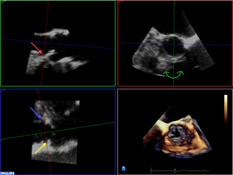
|
4. Rotating the blue plane will help in assuring that the transverse view is bisecting the hinge point at the level of the non and left coronary cusps: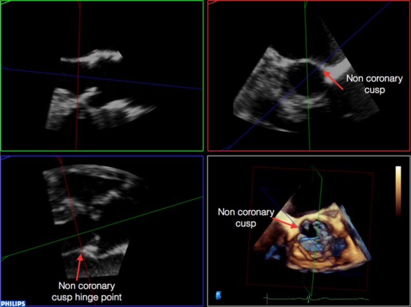 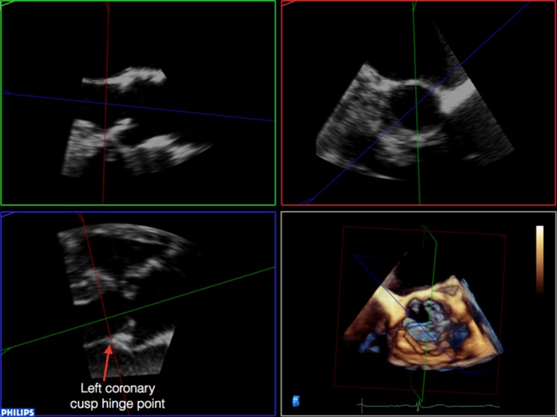
|
5. Select the transverse plane image from this dataset: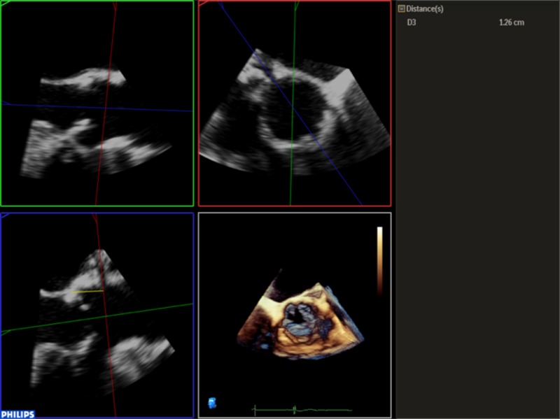
|
| 6. Trace the circumference and area of the annulus by pointing and clicking in an iterative manner around it. This is done in a similar manner to CT, by using the inner edge of the annulus, ignoring any soft low intensity echoes and irregular bright (calcium) indentations, which are traced through. |
7. Once the annulus has been measured, it is possible to identify the ostium of the left main coronary artery and measure the distance between this and the base of the left coronary cusp (any measurement below 11 mm is considered too small to accommodate valve expansion without significant risk of coronary ostial occlusion). Firstly, align the sagittal and coronal planes to bisect the long-axis of the aortic valve. The red marker line on the sagittal plane is then advanced cranially along the aortic root until the origin of the left main stem (LMS) is identified as an indentation at roughly the 10 O’clock position of the transverse image. The green marker of the transvers image is then rotated anti-clockwise until it is aligned with the LMS ostium. The distance from the base of the left coronary cusp to the ostium can then be measured as shown by the yellow marker: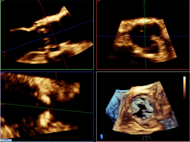 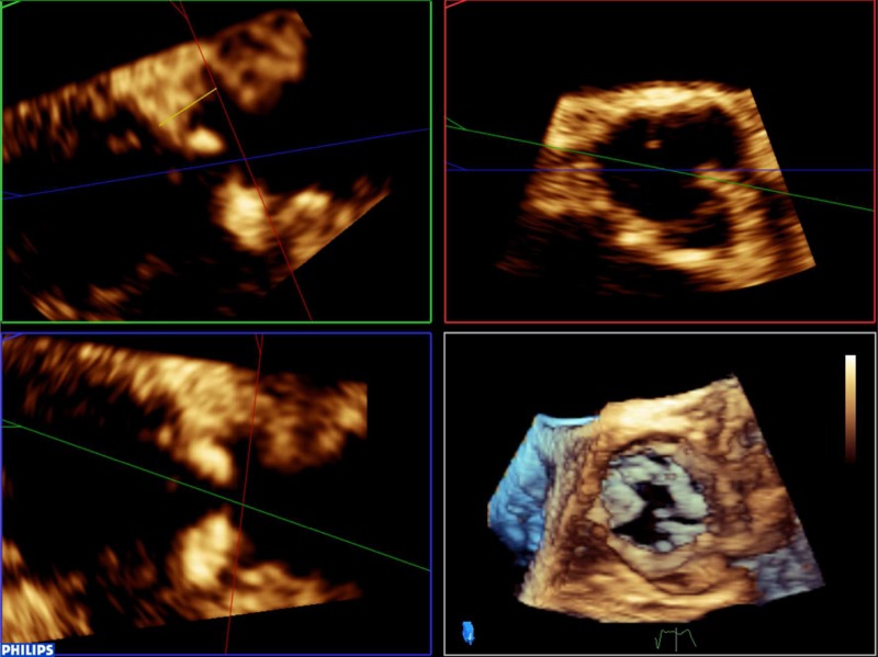
|
Pitfalls
Dropout caused by extensive calcification in the LVOT is a potential cause of inaccuracy in the 3D TOE measurement of the aortic annulus. Adjusting each plane to minimise this effect can allow accurate measurements to still be gained; however, this must not be at the expense of losing sight of the actual annulus by over-manipulating the planes of view. It is also necessary to eliminate the base of the aortic cusps from the measurement by carefully rotating the orthogonal plane to ensure that what is being measured reflects the virtual annulus.
Declaration of interest
The authors declare that there is no conflict of interest that could be perceived as prejudicing the impartiality of this review.
Funding
This research did not receive any specific grant from any funding agency in the public, commercial or not-for-profit sector.
Acknowledgements
Supported in part by a National Institute for Health Research Biomedical Research Centre award to Guy’s and St Thomas’ Hospital and King’s College London in partnership with King’s College Hospital.
References
- 1.Ciobotaru V, Maupas E, Dürrleman N, Boulenc J-M, Borton A, Pujadas-Berthault P, Rioux P, Maubon A. 2016. Predictive value for paravalvular regurgitation of 3-dimensional anatomic aortic annulus shape assessed by multidetector computed tomography post-transcatheter aortic valve replacement. European Heart Journal: Cardiovascular Imaging 17 85–95. ( 10.1093/ehjci/jev128) [DOI] [PubMed] [Google Scholar]
- 2.Kasel AM, Cassese S, Bleiziffer S, Amaki M, Hahn RT, Kastrati A, Sengupta PP. 2013. Standardized imaging for aortic annular sizing: implications for transcatheter valve selection. JACC: Cardiovascular Imaging 6 249–262. ( 10.1016/j.jcmg.2012.12.005) [DOI] [PubMed] [Google Scholar]
- 3.Mehrotra P, Flynn AW, Jansen K, Tan TC, Mak G, Julien HM, Zeng X, Picard MH, Passeri JJ, Hung J. 2015. Differential left ventricular outflow tract remodeling and dynamics in aortic stenosis. Journal of the American Society of Echocardiography 28 1259–1266. ( 10.1016/j.echo.2015.07.018) [DOI] [PubMed] [Google Scholar]
- 4.Kenny C, Monaghan M. 2015. How to assess aortic annular size before transcatheter aortic valve implantation (TAVI): the role of echocardiography compared with other imaging modalities. Heart 101 727–736. ( 10.1136/heartjnl-2013-304689) [DOI] [PubMed] [Google Scholar]
- 5.Ng ACT, Delgado V, van der Kley F, Shanks M, van de Veire NRL, Bertini M, Nucifora G, van Bommel RJ, Tops LF, de Weger A, et al. 2010. Comparison of aortic root dimensions and geometries before and after transcatheter aortic valve implantation by 2- and 3-dimensional transesophageal echocardiography and multislice computed tomography. Circulation: Cardiovascular Imaging 3 94–102. ( 10.1161/circimaging.109.885152) [DOI] [PubMed] [Google Scholar]
- 6.Schultz CJ, Weustink A, Piazza N, Otten A, Mollet N, Krestin G, van Geuns RJ, de Feyter P, Serruys PW, de Jaegere P. 2009. Geometry and degree of apposition of the CoreValve ReValving system with multislice computed tomography after implantation in patients with aortic stenosis. Journal of the American College of Cardiology 54 911–918. ( 10.1016/j.jacc.2009.04.075) [DOI] [PubMed] [Google Scholar]
- 7.Kim W-K, Meyer A, Möllmann H, Rolf A, Möllmann S, Blumenstein J, Van Linden A, Hamm CW, Walther T, Kempfert J. 2016. Cyclic changes in area- and perimeter-derived effective dimensions of the aortic annulus measured with multislice computed tomography and comparison with metric intraoperative sizing. Clinical Research in Cardiology 105 622–629. ( 10.1007/s00392-016-0971-3) [DOI] [PubMed] [Google Scholar]
- 8.Khalique OK, Kodali SK, Paradis J-M, Nazif TM, Williams MR, Einstein AJ, Pearson GD, Harjai K, Grubb K, George I, et al. 2014. Aortic annular sizing using a novel 3-dimensional echocardiographic method: use and comparison with cardiac computed tomography. Circulation: Cardiovascular Imaging 7 155–163. ( 10.1161/circimaging.113.001153) [DOI] [PubMed] [Google Scholar]
- 9.Hamdan A, Guetta V, Konen E, Goitein O, Segev A, Raanani E, Spiegelstein D, Hay I, Di Segni E, Eldar M, et al. 2012. Deformation dynamics and mechanical properties of the aortic annulus by 4-dimensional computed tomography: insights into the functional anatomy of the aortic valve complex and implications for transcatheter aortic valve therapy. Journal of the American College of Cardiology 59 119–127. ( 10.1016/j.jacc.2011.09.045) [DOI] [PubMed] [Google Scholar]
- 10.Smith LA, Dworakowski R, Bhan A, Delithanasis I, Hancock J, MacCarthy PA, Wendler O, Thomas MR, Monaghan MJ. 2013. Real-time three-dimensional transesophageal echocardiography adds value to transcatheter aortic valve implantation. Journal of the American Society of Echocardiography 26 359–369. ( 10.1016/j.echo.2013.01.014) [DOI] [PubMed] [Google Scholar]
- 11.Blanke P, Willson AB, Webb JG, Achenbach S, Piazza N, Min JK, Pache G, Leipsic J. 2014. Oversizing in transcatheter aortic valve replacement, a commonly used term but a poorly understood one: dependency on definition and geometrical measurements. Journal of Cardiovascular Computed Tomography 8 67–76. ( 10.1016/j.jcct.2013.12.020) [DOI] [PubMed] [Google Scholar]
- 12.Mihara H, Shibayama K, Berdejo J, Harada K, Itabashi Y, Siegel RJ, Kashif M, Jilaihawi H, Makkar RR, Shiota T. 2015. Impact of device landing zone calcification on paravalvular regurgitation after transcatheter aortic valve replacement: a real-time three-dimensional transesophageal echocardiographic study. Journal of the American Society of Echocardiography 28 404–414. ( 10.1016/j.echo.2014.11.013) [DOI] [PubMed] [Google Scholar]
- 13.Willson AB, Webb JG, LaBounty TM, Achenbach S, Moss R, Wheeler M, Thompson C, Min JK, Gurvitch R, Norgaard BL, et al. 2012. 3-Dimensional aortic annular assessment by multidetector computed tomography predicts moderate or severe paravalvular regurgitation after transcatheter aortic valve replacement: a multicenter retrospective analysis. Journal of the American College of Cardiology 59 1287–1294. ( 10.1016/j.jacc.2011.12.015) [DOI] [PubMed] [Google Scholar]
- 14.Popma JJ, Gleason TG, Yakubov SJ, Harrison JK, Forrest JK, Maini B, Ruiz CE, Pinto DS, Costa M, Resar J, et al. 2016. Relationship of annular sizing using multidetector computed tomographic imaging and clinical outcomes after self-expanding CoreValve transcatheter aortic valve replacement Circulation: Cardiovascular Interventions 9 e003282 ( 10.1161/circinterventions.115.003282) [DOI] [PubMed] [Google Scholar]
- 15.Hahn RT, Gillam LD, Little SH. 2015. Echocardiographic imaging of procedural complications during self-expandable transcatheter aortic valve replacement. JACC: Cardiovascular Imaging 8 319–336. ( 10.1016/j.jcmg.2015.01.001) [DOI] [PubMed] [Google Scholar]
- 16.Ludman PF, Moat N, de Belder MA, Blackman DJ, Duncan A, Banya W, MacCarthy PA, Cunningham D, Wendler O, Marlee D, et al. 2015. Transcatheter aortic valve implantation in the UK: temporal trends, predictors of outcome and 6 year follow up: a report from the UK TAVI registry 2007 to 2012 Circulation 131 1181–1190. ( 10.1161/circulationaha.114.013947) [DOI] [PubMed] [Google Scholar]
- 17.Jochheim D, Schneider VS, Schwarz F, Kupatt C, Lange P, Reiser M, Massberg S, Gutiérrez-Chico JL, Mehilli J, Becker HC. 2014. Contrast-induced acute kidney injury after computed tomography prior to transcatheter aortic valve implantation. Clinical Radiology 69 1034–1038. ( 10.1016/j.crad.2014.05.106) [DOI] [PubMed] [Google Scholar]
- 18.Cernigliaro JG, Haley WE, Adolphson DP, Jepperson MA, Crook JE, Thomas CS, Parker AS. 2016. Contrast-induced nephropathy in outpatients with preexisting renal impairment: a comparison between intravenous iohexol and iodixanol. Clinical Imaging 40 902–906. ( 10.1016/j.clinimag.2016.04.008) [DOI] [PubMed] [Google Scholar]
- 19.Achenbach S, Delgado V, Hausleiter J, Schoenhagen P, Min JK, Leipsic JA. 2012. SCCT expert consensus document on computed tomography imaging before transcatheter aortic valve implantation (TAVI)/transcatheter aortic valve replacement (TAVR). Journal of Cardiovascular Computed Tomography 6 366–380. ( 10.1016/j.jcct.2012.11.002) [DOI] [PubMed] [Google Scholar]
- 20.Leipsic J, Gurvitch R, LaBounty TM, Min JK, Wood D, Johnson M, Ajlan AM, Wijesinghe N, Webb J G. 2011. Multidetector computed tomography in transcatheter aortic valve implantation. JACC: Cardiovascular Imaging 4 416–429. ( 10.1016/j.jcmg.2011.01.014) [DOI] [PubMed] [Google Scholar]
- 21.Kiramijyan S, Magalhaes MA, Koifman E, Didier R, Escarcega RO, Minha S, Baker NC, Negi SI, Torguson R, Gai J, et al. 2016. Impact of baseline mitral regurgitation on short- and long-term outcomes following transcatheter aortic valve replacement. American Heart Journal 178 19–27. ( 10.1016/j.ahj.2016.03.020) [DOI] [PubMed] [Google Scholar]
- 22.Cortés C, Amat-Santos IJ, Nombela-Franco L, Muñoz-Garcia AJ, Gutiérrez-Ibanes E, De La Torre Hernandez JM, Córdoba-Soriano JG, Jimenez-Quevedo P, Hernández-García JM, Gonzalez-Mansilla A, et al. 2016. Mitral regurgitation after transcatheter aortic valve replacement: prognosis, imaging predictors, and potential management. JACC: Cardiovascular Interventions 9 1603–1614. ( 10.1016/j.jcin.2016.05.025) [DOI] [PubMed] [Google Scholar]
- 23.Hahn RT, Abraham T, Adams MS, Bruce CJ, Glas KE, Lang RM, Reeves ST, Shanewise JS, Siu SC, Stewart W, et al. 2013. Guidelines for performing a comprehensive transesophageal echocardiographic examination: recommendations from the American Society of Echocardiography and the Society of Cardiovascular Anesthesiologists. Journal of the American Society of Echocardiography 26 921–964. ( 10.1016/j.echo.2013.07.009) [DOI] [PubMed] [Google Scholar]
- 24.Zamorano JL, Badano LP, Bruce C, Chan K-L, Gonçalves A, Hahn RT, Keane MG, La Canna G, Monaghan MJ, Nihoyannopoulos P, et al. 2011. EAE/ASE recommendations for the use of echocardiography in new transcatheter interventions for valvular heart disease. European Heart Journal 32 2189–2214. ( 10.1093/eurheartj/ehr259) [DOI] [PubMed] [Google Scholar]
- 25.Tsang W, Bateman MG, Weinert L, Pellegrini G, Mor-Avi V, Sugeng L, Yeung H, Patel AR, Hill AJ, Iaizzo PA, et al. 2012. Accuracy of aortic annular measurements obtained from three-dimensional echocardiography, CT and MRI: human in vitro and in vivo studies. Heart 98 1146–1152. ( 10.1136/heartjnl-2012-302074) [DOI] [PubMed] [Google Scholar]
- 26.Husser O, Holzamer A, Resch M, Endemann DH, Nunez J, Bodi V, Schmid C, Riegger GA, Gössmann H, Hamer O, et al. 2013. Prosthesis sizing for transcatheter aortic valve implantation – comparison of three dimensional transesophageal echocardiography with multislice computed tomography. International Journal of Cardiology 168 3431–3438. ( 10.1016/j.ijcard.2013.04.182) [DOI] [PubMed] [Google Scholar]
- 27.Wang H, Hanna JM, Ganapathi A, Keenan JE, Hurwitz LM, Vavalle JP, Kiefer TL, Wang A, Harrison JK, Hughes GC. 2015. Comparison of aortic annulus size by transesophageal echocardiography and computed tomography angiography with direct surgical measurement. American Journal of Cardiology 115 1568–1573. ( 10.1016/j.amjcard.2015.02.060) [DOI] [PubMed] [Google Scholar]
- 28.Stortecky S, Heg D, Gloekler S, Wenaweser P, Windecker S, Buellesfeld L. 2014. Accuracy and reproducibility of aortic annulus sizing using a dedicated three-dimensional computed tomography reconstruction tool in patients evaluated for transcatheter aortic valve replacement. EuroIntervention 10 339–346. ( 10.4244/eijv10i3a59) [DOI] [PubMed] [Google Scholar]
- 29.Faletti R, Gatti M, Salizzoni S, Bergamasco L, Bonamini R, Garabello D, Marra WG, La Torre M, Morello M, Veglia S, et al. 2016. Cardiovascular magnetic resonance as a reliable alternative to cardiovascular computed tomography and transesophageal echocardiography for aortic annulus valve sizing. International Journal of Cardiovascular Imaging 32 1255–1263. ( 10.1007/s10554-016-0899-8) [DOI] [PubMed] [Google Scholar]
- 30.Rendon A, Hamid T, Kanaganayagam G, Karunaratne D, Mahadevan VS. 2016. Annular sizing using real-time three-dimensional intracardiac echocardiography-guided trans-catheter aortic valve replacement. Open Heart 3 e000316 ( 10.1136/openhrt-2015-000316) [DOI] [PMC free article] [PubMed] [Google Scholar]
- 31.Gripari P, Ewe SH, Fusini L, Muratori M, Ng ACT, Cefalù C, Delgado V, Schalij MJ, Bax JJ, Marsan NA, et al. 2012. Intraoperative 2D and 3D transoesophageal echocardiographic predictors of aortic regurgitation after transcatheter aortic valve implantation. Heart 98 1229–1236. ( 10.1136/heartjnl-2012-301998) [DOI] [PubMed] [Google Scholar]
- 32.Buzzatti N, Maisano F, Latib A, Cioni M, Taramasso M, Mussardo M, Colombo A, Alfieri O. 2013. Computed tomography-based evaluation of aortic annulus, prosthesis size and impact on early residual aortic regurgitation after transcatheter aortic valve implantation. European Journal of Cardio-Thoracic Surgery 43 43–51. ( 10.1093/ejcts/ezs155) [DOI] [PubMed] [Google Scholar]
- 33.García-Martín A, Lázaro-Rivera C, Fernández-Golfín C, Salido-Tahoces L, Moya-Mur J-L, Jiménez-Nacher J-J, Casas-Rojo E, Aquila I, González-Gómez A, Hernández-Antolín R, et al. 2016. Accuracy and reproducibility of novel echocardiographic three-dimensional automated software for the assessment of the aortic root in candidates for thanscatheter aortic valve replacement. European Heart Journal: Cardiovascular Imaging 17 772–778. ( 10.1093/ehjci/jev204) [DOI] [PubMed] [Google Scholar]
- 34.Schultz CJ, Rodriguez-Olivares R, Bosmans J, Lefèvre T, De Santis G, Bruining N, Collas V, Dezutter T, Bosmans B, Rahhab Z, et al. Patient-specific image-based computer simulation for the prediction of valve morphology and calcium displacement after TAVI with the Medtronic CoreValve and the Edwards SAPIEN valve. EuroIntervention 11 1044–1052. ( 10.4244/eijv11i9a212) [DOI] [PubMed] [Google Scholar]


 This work is licensed under a