Abstract
Dual energy CT imaging has many potential uses in abdominal imaging. It also has unique requirements for protocol creation depending on the dual energy scanning technique that is being utilized. It also generates several new types of images which can increase the complexity of image creation and image interpretation. The purpose of this article is to review, for rapid switching and dual source dual energy platforms, methods for creating dual energy protocols, different approaches for efficiently creating dual energy images and an approach to navigating and using dual energy images at the reading station all using the example of a pancreatic multiphasic protocol. It will also review the three most commonly used types of dual energy images: “workhorse” 120kVp surrogate images (including blended polychromatic and 70keV monochromatic), high contrast images (e.g. low energy monochromatic and iodine material decomposition images), and virtual unenhanced images. Recent developments, such as the ability to create automatically on the scanner the most common dual energy images types, namely new “Mono +” images for the DSDECT (dual source dual energy CT) platform will also be addressed. Finally, an approach to image interpretation using automated “hanging protocols” will also be covered. Successful dual energy implementation in a high volume practice requires careful attention to each of these steps of scanning, image creation, and image interpretation.
Keywords: Dual energy, computed tomography, workflow
Introduction
The development of dual-energy CTs (DECT) has yielded several opportunities to improve imaging. One of DECT’s major strengths is improving visualization of contrast enhancement, potentially increasing the visibility of such entities as hypervascular liver lesions, [1] hypodense and hyperdense pancreatic tumors [2–4], and pulmonary emboli [5,6]. Early work shows dual energy CT also has the ability to provide information that would have required separate pre-and postcontrast imaging, offering opportunities for decreasing radiation dose [7], as well as providing unique information that is being increasingly utilized to characterize materials, for example the management of gout [8], and the removal of calcified plaque to improve the accuracy of CT angiography for such purposes as the assessment of vascular stenoses [9].
There are several challenges involved in the incorporation of dual-energy CT into an abdominal imaging practice. Unlike earlier CT developments that involved essentially increasing the speed of imaging over earlier generations of scanners, dual energy imaging creates new types of images. Developing imaging protocols that can scan patients efficiently and optimally, optimizing workflows to generate these new types of images, and establishing an efficient approach to the interpretation of these images are necessary for a successful implementation of DECT.
This manuscript will provide a brief review of what is dual energy imaging followed then by a discussion of the steps involved for creating dual-energy imaging protocols, creating dual-energy specific images, and efficiently interpreting dual energy studies based on our experience in a high volume abdominal imaging practice.
Review of the Principles of Dual Energy/Multispectral Imaging
Multispectral CT, often called “dual energy” CT, provides new and additional information beyond conventional CT by providing information regarding tissue densities as measured at different incident x-ray photon energies compared to the single value obtained from conventional imaging from imaging with a single polychromatic beam (e.g. 120kVp). The technique is commonly referred to as “dual energy” CT because this information has typically been obtained by exposing tissues to polychromatic x-ray beams of two different energies (typically 80–100kVp and 140 kVp). [10,11] It is notable that these two beams are themselves made up of a range of energies, and are therefore described as “polychromatic.”
Many different approaches to “dual energy” imaging are now available, [10] such that the term “multispectral CT” may be more appropriate. A full review of the many different approaches is beyond the scope of this article and has been covered elsewhere [10,12,13]. A brief summary of dual energy approaches would include the following: 1) dual source dual-energy CT (DSDECT) (SOMATOM Dual Source Definition Flash, Force and Drive, Siemens Healthcare) in which two separate x-ray tubes emit two different energies simultaneously during a scan, 2) rapid switching dual-energy CT (RSDECT) in which a single x-ray tube rapidly switches between two different x-ray energies (Discovery HD750/Revolution 750HD and Revolution, General Electric Healthcare), 3) “split beam” dual-energy CT in which a single x-ray tube emits a beam that is “split” (through use of a metallic filter) to yield a beam of two different energies during the same scan (SOMATOM Definition Edge, Siemens Healthcare), and 4) “double scan” dual-energy CT in which two sequential scans are obtained at two different energies (this last approach is more problematic because of the likelihood of movement, and therefore misregistration, between scans). A recent development is the use of a unique detector to discriminate between incoming high and low energy x-ray photons to derive spectral data from a single conventional polychromatic 120 kVp x-ray beam (IQon, Phillips Healthcare).
We will discuss in this monograph dual source (DSDECT) and rapid switching (RSDECT) dual energy CT because those are the techniques utilized by the CT equipment installed at our institution.
Review of the Most Common Types of Dual Energy Images
Probably the most commonly used dual energy images are variably blended polychromatic images, virtual monochromatic energy images (because these are created mathematically), and material decomposition/material density (MDI) images. Each will be addressed in turn.
Blended Polychromatic Images
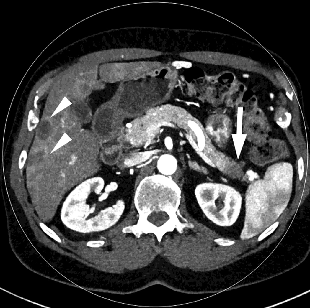
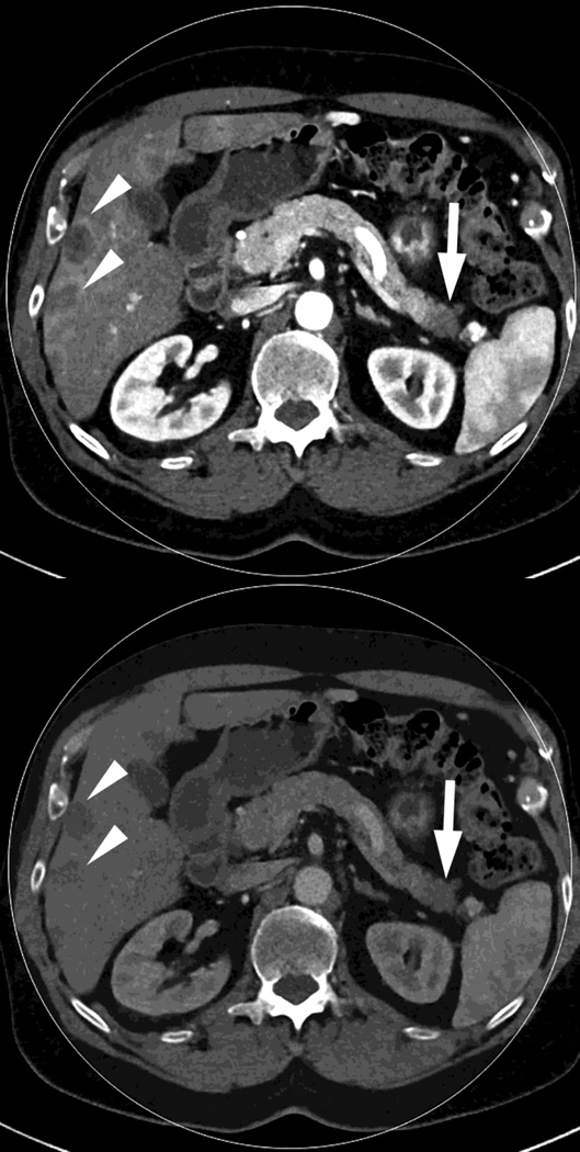
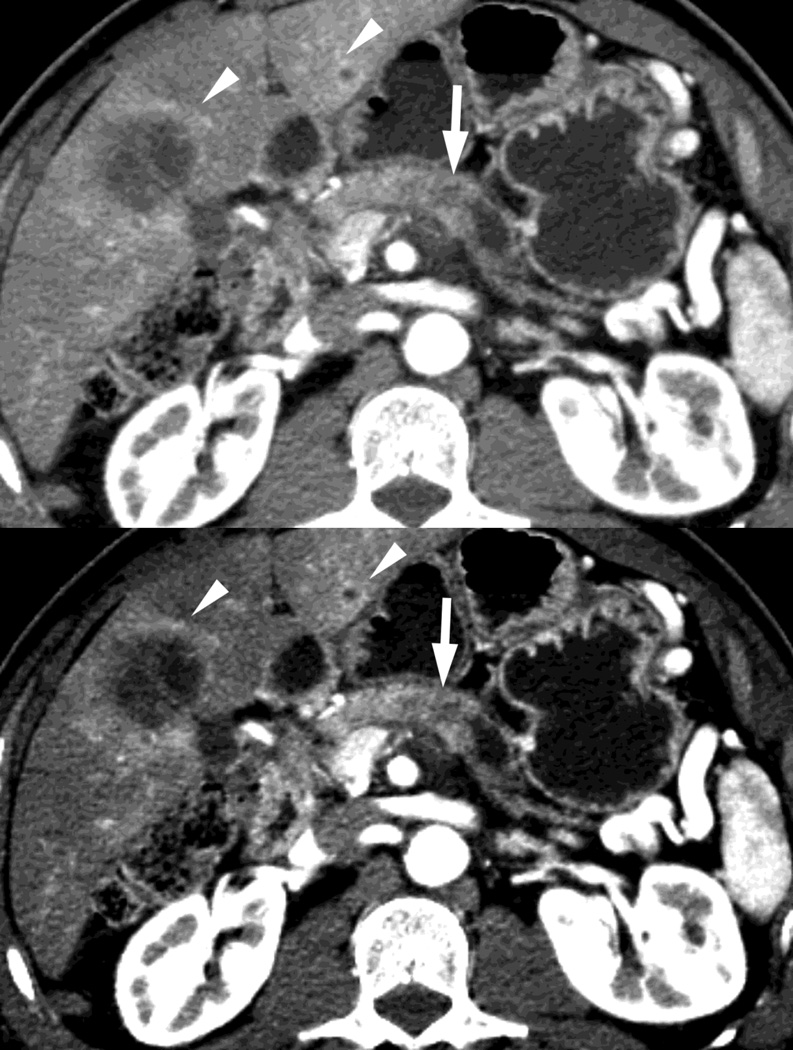
These are images based on the entirety of the data from the two x-ray beams. In the dual source (DSDECT) system that we utilize (SOMATOM Definition Flash, Siemens), these are blended to the user’s preference (Fig. 1), with emphasis ranging from the lower energy polychromatic beam (e.g. usually 80 or 100kVp) values up to 140kVp [14]. The lower energy values enhance the conspicuity of differences in contrast enhancement at the expense of noise because the mean energy is closer to the k-edge of iodine, thus maximizing the photoelectric effect, while high energy images do the reverse. The blend is often linear, but other approaches including sigmoidal, have also been described [11,15–17]. This approach, like conventional imaging, is susceptible to beam hardening, the progressive filtering of weaker x-ray beams as they proceed from the periphery to the center of an imaged object, but also have potentially less noise than monochromatic energy images because they use the entirety of the energy spectra in a weighted fashion to obtain the desired image quality without compromising radiation dose. [11]
Fig. 1.
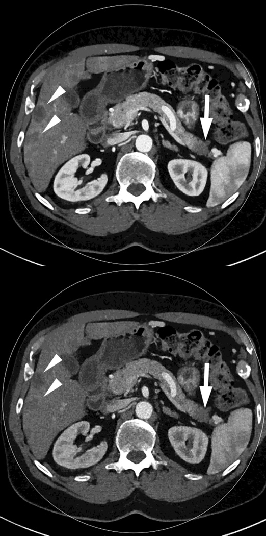
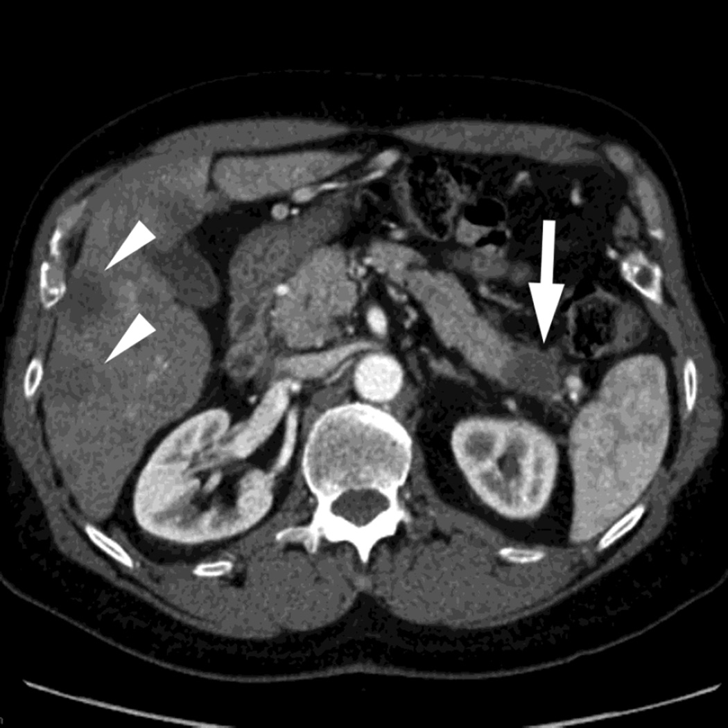
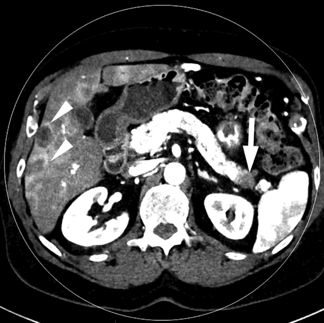
Polychromatic blended images from dual source dual energy (DSDECT) (A–C) and rapid switching dual energy scans (RSDECT) (D) same patient, pancreatic tail ductal adenocarcinoma, same windowing, scans obtained 2 months apart. The DSDECT platform can create polychromatic energy images from variably "blending" data from the low (here 100kVp) and 140kVp data, with examples as shown, A) low energy (closer to 100kVp), B) mid (120kVp) and C) high (e.g. 140kVp). Low energy images emphasize contrast enhancement. Pancreatic cancer tumor (white arrow) and liver metastases (white arrowheads) are more conspicuous on the low energy images. The dotted circle indicates the area covered by dual energy imaging. Imaging outside of the circle is based solely on data from a single energy (here 100kVp). In contrast, the RSDECT scanner provides a polychromatic "quality control" series D), not meant for interpretation, and based solely on the 140kVp polychromatic data. We have nevertheless found this series useful as an adjunct for interpretation.
The rapid switching dual energy system does not offer at this time blended polychromatic images. Incompletely processed, “quality control” images based solely on the 140 kVp data are available as a rapidly obtainable “quality check” for technologists during an imaging examination (Fig. 1). Our anecdotal experience has been that these images are useful as an adjunct particularly in those cases where the low energy beam may be compromised (e.g. large patient habitus, interaction with very high density material, etc.).
Virtual Monochromatic Energy Images
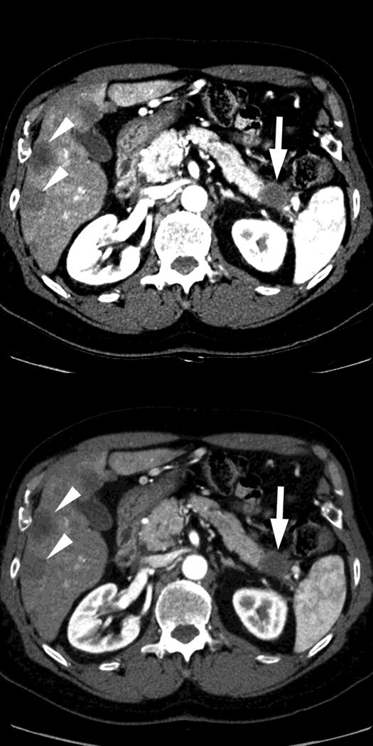
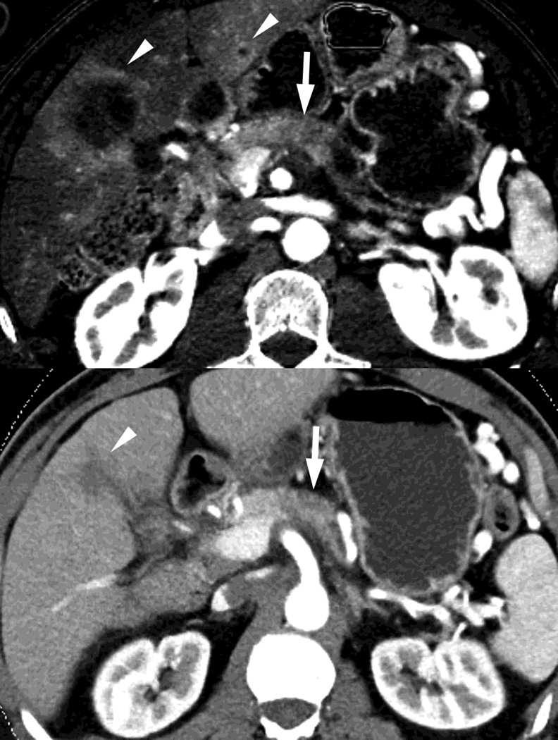
Virtual monochromatic (also called monoenergetic) energy images are mathematically created images based on a single, discrete energy level, usually referred to in terms of keV. For example, a 40keV image is based on only a single discrete energy at the 40keV level (monochromatic), in contrast to a 120kVp image that is based on data from photons ranging in energy up to a maximum of 120keV (polychromatic). [11] There is no beam hardening with this technique as there is only one energy level on which an image is based. A primary benefit of such images is that images can be created based on a lower simulated x-ray beam energy to improve soft tissue contrast, especially useful when iodine enhancement is present. Monochromatic reconstructions can also be used to generate images that are a close match to a conventional polychromatic image (e.g. 120kVp) as a useful comparison to prior conventional exams. Both types of images are available with the dual source and rapid switching platforms (Fig. 2). A recent development on the DSDECT platform is a second generation monoenergectic reconstruction algorithm (“Mono +”) that has been shown to improve image quality for the DSDECT platform (Fig. 2). [18,19]
Fig. 2.
Monochromatic energy images from same patient, imaged 2 months apart, as in Figure 1, for DSDECT, "Mono + algorithm," (A–C) and RSDECT (D–F) at 50 kev (A,D), 70 kev (B,E), and 140 keV (C,F). Images are all at the same window setting. Pancreatic tail tumor (white arrow) and liver metastases (white arrowheads). Enhancement becomes more conspicuous at lower keV. Note the difference in enhancement between the pancreatic tail tumor and adjacent pancreas..
Virtual monochromatic images are typically created at energy levels ranging from 40–140keV, values available to both systems, but the full range may be wider for particular scanner systems. Because the k edge of iodine is at 33 keV, low energy (e.g. 40–50keV) images enhance the conspicuity of the presence of iodine (and enhance the visibility of differences in contrast enhancement) at the expense of increased noise, while 140keV images minimize the presence of iodine (Fig. 2), and also minimize scatter and beam hardening (making them useful for imaging regions with metal and as a type of surrogate for virtual unenhanced image in some examinations). [11]
It is notable that choosing the appropriate energy level can provide a surrogate for a conventional polychromatic energy image. For example, 70–78 keV images correlate approximately with the appearance of images conventionally obtained at 100–120kVp, while improving contrast to noise over 120kVp [13,20]. For the rapid switching platform, we typically create a 70 keV set of images for routine review.
Material Decomposition Images
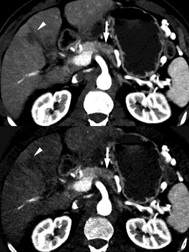
The third most commonly obtained image type are material decomposition images (Fig. 3, 4). These are images created mathematically by “decomposing” acquired dual energy imaging data for each voxel in an image into relative amounts of a limited number of chosen materials whose behavior together mimics the actual behavior at that voxel under dual energy imaging. These chosen limited materials are those for which there are known reported density values at different x-ray energies. The number of these chosen materials that can be resolved (usually two or three) depends on the mathematical model employed by the scanner manufacturer. Three such known materials which fit along the spectrum of the densities typically encountered in medical imaging are water, iodine and fat. [21]
Fig. 3.
Patient with small islet cell tumor (white arrow) imaged on the RSDECT platform that is seen on A) iodine-water, or iodine(-water), material density image, but not on the B) water-iodine, or water(-iodine) image confirming an enhancing lesion. The values within the voxels of this pair of images are actually calculated values of the density needed of the combination of water (on the water-iodine image) and iodine (as seen on the iodine-water image) needed to mimic the actual behavior at that voxel as measured at 80 and 140 kVp, The water image is utilized as a virtual noncontrast image, and the iodine image is utilized as a high contrast series to maximize the conspicuity of differences in contrast enhancement.
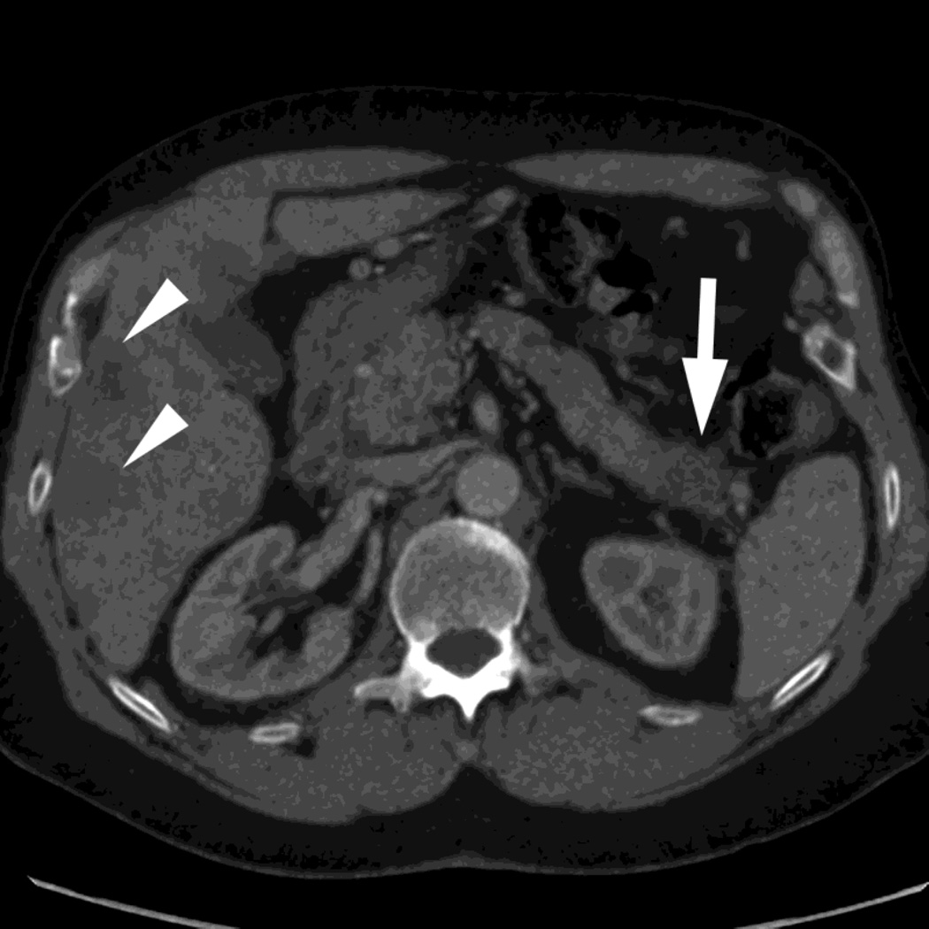
Fig. 4.
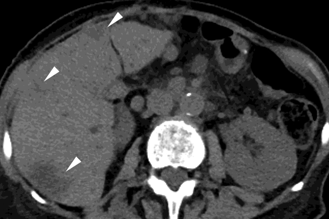
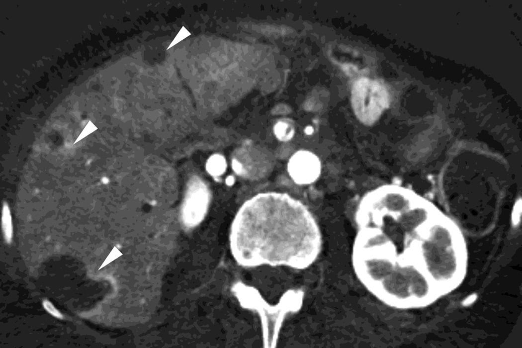
Patient with recurrent pancreatic cancer that has metastasized (white arrowheads) to the liver. The DSDECT platform utilizes three material decomposition (iodine, fat and soft tissue) in the creation of A) virtual unenhanced and B) iodine material decomposition images. Measurements of the values from the virtual unenhanced image yield Hounsfield values.
The rapid switching approach generally utilizes 2 material decomposition (Fig. 3). In this technique, two materials are chosen, e.g. water and iodine, whose physical properties, including density values at different x-ray energies, are known. Then the density data for each voxel (at 80kVp and 140kVp together) in an image is then “decomposed” into the density of each of the two materials (e.g. water and iodine) that would have needed to have been present in each voxel (and just those two materials) to create the density measurements actually observed at 80kVp and 140kVp for each voxel. [12] Two sets of images can then be created, each based on one material’s density values for each voxel: 1) the images based on the water density values, conventionally called water (-iodine) or water (iodine), and 2) the images based on the iodine density values, conventionally called iodine (-water) or iodine (water). [11]
In contrast, the dual source technique utilizes three material decomposition (iodine, fat and a calculated value for soft tissue). [12,21] This approach can be utilized to create (Fig. 4) a virtual unenhanced image as well as an iodine only image.
Please note, these models necessarily utilize a simplification of the chemical composition of each voxel (as composed of two or three materials rather than its true composition of many materials) and therefore these are semi-quantitative measures of the amounts of materials needed to be present to mimic the behavior of the actual materials present, rather than the true amounts of each material, e.g. the calculated amounts of iodine necessarily include also “pseudo-iodine.”
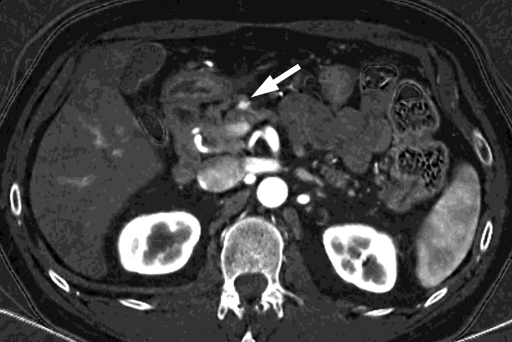
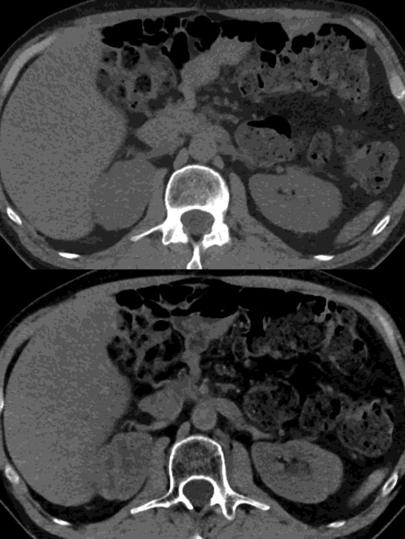
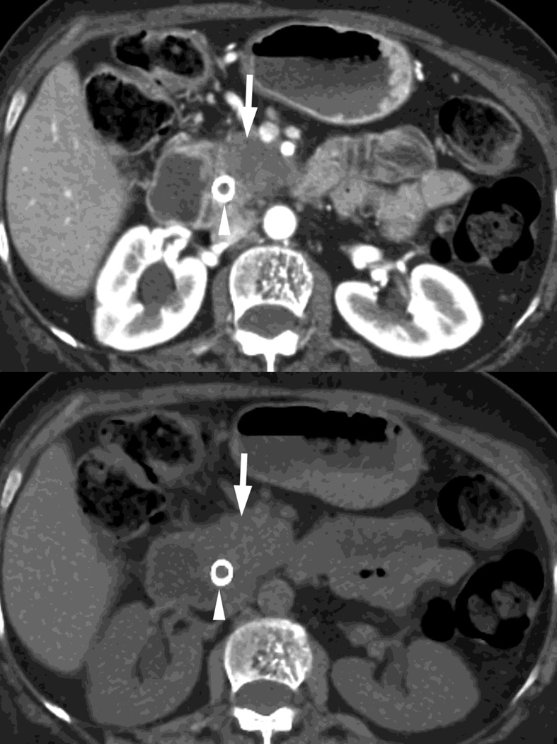
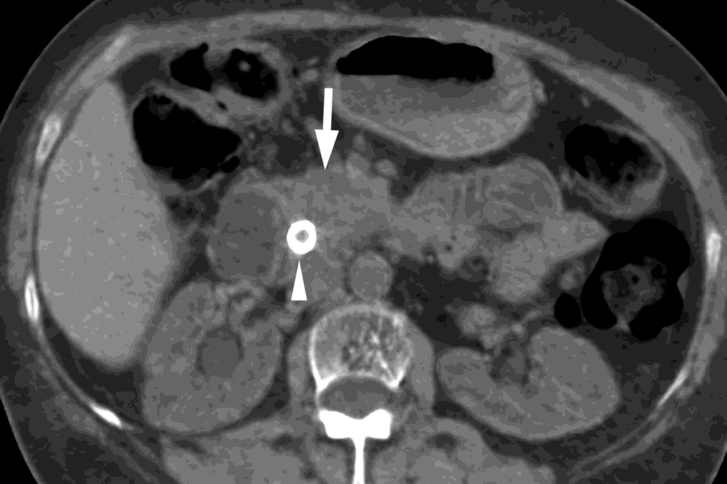
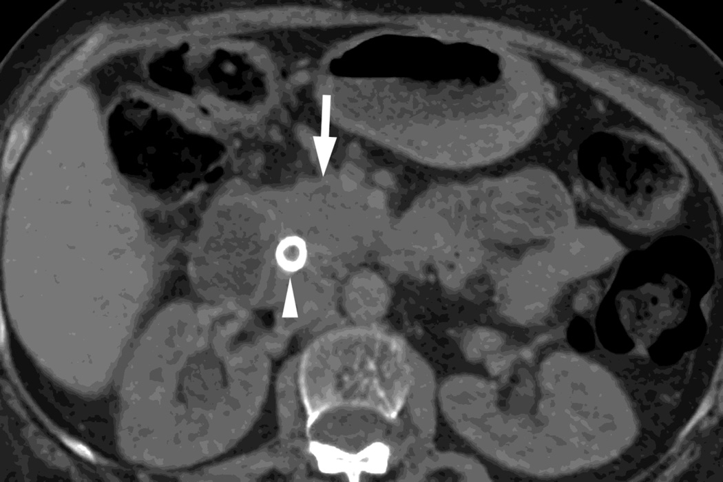
Nevertheless, these techniques are very useful. One of the benefits is the creation of virtual unenhanced images (VUE) (Fig. 5, 6). [7,12,13,22] These images minimize the presence of iodine. The technique for creating these images differs between the two platforms. On the dual source platform (Fig. 5), virtual unenhanced images are created by three material decomposition and Hounsfield units can be readily obtained from the image. [14] On the rapid switching platform (Fig. 6), there are two different approaches: 1) two material decomposition, and 2) three material decomposition. The two material decomposition approach results in a water (-iodine) image that provides a density value (such images are also described as “material density” images). [12,13] The second type, called material suppressed iodine (MSI), substitutes an equal volume of blood for the iodine removed in its calculations and can provide a calculated precontrast Hounsfield unit value. [22,23] For both platforms in our facility, we obtain a true precontrast acquisition for our pancreas protocol. While these processed DECT virtual unenhanced images still differ somewhat in appearance from true precontrast images, they have been described as being useful for a variety of purposes (characterization of adenomas, identification of enhancement in cystic lesions, etc.) and can be used as a “stand in” for true precontrast images in some settings. [12–14,24–26] Therefore, depending on the clinical scenario, radiologists at a given imaging facility may not find it necessary to obtain true unenhanced images when virtual unenhanced images are available. We currently still acquire both as we are still learning about the ability of virtual unenhanced images to replace true precontrast images in the setting of pancreatic oncology.
Fig. 5.
DSDECT, pancreatic parenchymal phase of patient, status post Whipple procedure without recurrence, with A) 100–120kVp blended equivalent polychromatic, B) true precontrast and C) virtual noncontrast images.
Fig. 6.
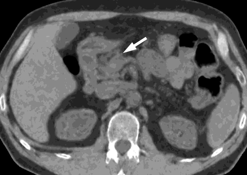
RSDECT scan, pancreatic parenchymal phase of patient with pancreatic head ductal adenocarcinoma (white arrow) as seen on A)70keV monochromatic B) true precontrast, C) water-iodine or water(-iodine), and D) material suppressed iodine (MSI). The water(-iodine) yields measurements in calculated density, while an ROI on the MSI image would provide calculated Hounsfield units. Note the appearance of the renal cortex on the virtual noncontrast images versus the true precontrast image. A metallic common bile duct stent is present within the pancreatic head (white arrowhead)
Another benefit is the creation of “iodine” images (Fig. 3, 4, 7), which provide information regarding the amount of iodine present, and enhance the visualization of differences in contrast enhancement. [3,12,13,26,27] These have been described as having an appearance similar to “substraction” images (those based on subtracting precontrast from postcontrast images) without the misregistration artifact that commonly plagued such images. These, like low energy monochromatic energy images, increase the conspicuity of contrast enhancement.
Fig. 7.
Patient with small pancreatic body adenocarcinoma (white arrow) and liver metastases (white arrowheads) with examples of overview "workhorse" 100–120kVp equivalent, and high contrast series, for RSDECT, A) 70keV "workhorse", and high contrast B) 50 keV and C) iodine (water) material density image, and for DSDECT (here obtained 3months later), D) "workhorse" blended 100–120kVp polychromatic blend and high contrast E) 50keV and F) iodine material decomposition images. The near 120kVp equivalent image is used for most of the process of interpretation, with one or the other of the high contrast series utilized to facilitate identifying the primary tumor within the pancreas and its boundaries
Other types of material decomposition images can be created based on other materials, such as calcium, fat, etc., but are beyond the scope of our paper.
Other types of images, such as those created by calculating a virtual atomic number for each voxel, are utilized less commonly but are being investigated. For example, dual energy CT is being investigated by the radiation oncology community as a means to estimate electron density, effective atomic number decomposition and to quantify the presence of contrast material for potential applications in brachytherapy, and proton therapy. [28]
Utilization of Images
How these images are utilized will depend on the particular application to which dual energy imaging is being applied. For example, low energy monochromatic energy images and iodine specific images can be utilized to improve the conspicuity of hypervascular liver lesions. [1] Alternatively, in the setting of CT angiography, low energy monochromatic energy images can be utilized to create high contrast angiographic images in the setting of reduced contrast administration. [29] Specialized material decomposition images can be used in musculoskeletal imaging to evaluate gout. [30] Our practice has focused on the use of dual energy imaging in the setting of oncology and the discussion will now focus on the example of the use of dual energy CT in the setting of pancreatic oncology. We would note before doing so, that when planning to convert a protocol to DECT, to consult the literature and to make sure when doing so that the scanner technology utlized in those articles is the same as that for which the conversion to dual energy is being planned.
Pancreatic cancer is a challenging disease because of the variable conspicuity of this lesion against the surrounding heterogeneous background pancreas. Prior articles have shown that dual energy CT imaging can improve the conspicuity of pancreatic lesions. [3,31] We chose to create dual energy CT images for the pancreatic parenchymal phase of a multiphasic protocol with the goal of enhancing visualization of the primary tumor, and to create conventional portal venous phase images (120 kVp). We also acquire true precontrast images. As noted earlier, we are still learning about, and investigating, the ability of virtual unenhanced images to replace true precontrast images in the setting of pancreatic oncology. For both platforms, we avoid the use of breast shields to avoid compromise of the low energy beam and instead try to lower the overall dose as much as reasonably possible given the clinical needs driving the imaging evaluation. We use water as the gastrointestinal contrast.
The combination of specific dual energy image types we create for the pancreatic parenchymal phase depends on the imaging platform being utilized (dual source versus rapid switching) because of the different types of images available for each platform, particularly in regard to which images can be created automatically at the CT scanner and pushed to our Picture Archiving and Communications System (PACS). In general, we create a “workhorse” series for general review (a “surrogate” for “120kVp” imaging), one or more “high contrast” series to enhance the ability to visualize the primary tumor within the pancreas (low energy monochromatic and iodine material decomposition images), and a set of virtual unenhanced images to help with such issues in lesion characterization as identifying the presence of calcifications (Fig. 7). We currently are evaluating which series are most useful on each platform to simplify and minimize the number of series sent to our PACS, and to decrease the complexity of image interpretation.
On our dual source platform, we create a “workhorse” series of 3mm thick polychromatic blended images equivalent to conventional 100–120kVp images. We also create 3 mm thick 50keV images and iodine material decomposition images as our “high contrast” series to enhance visualization of the tumor from background pancreas, and 3 mm thick virtual unenhanced images (Fig. 7). We chose 50keV as a prior study showed that monochromatic energy images obtained near this level provided relatively optimal contrast between tumor and background for pancreatic cancer. [32] We also create virtual unenhanced images in addition to acquiring true precontrast images (Fig. 6).
On our rapid switching platform, we create 2.5mm thick 70 keV images as our workhorse series, since 70keV monochromatic images have a similar appearance to images created conventionally at 100–120kVp. Please note, we also make available to our radiologists the “QC” partially processed 2.5 mm thick images created conventionally from only the 140kVp beam as we have found these anecdotally to be a useful supplement (Fig. 1). We also create 2.5 mm thick 50 keV images and 2.5 mm iodine(-water) material decomposition images as our “high contrast” series (Fig. 7) and 2.5 mm thick virtual unenhanced, water (-iodine) material density images to aid in lesion characterization (Fig. 5). Currently, material suppressed iodine images can only be created with workstation software.
Converting a Conventional Protocol to a Dual Energy Protocol
As noted previously, there are several possible abdominal imaging applications for dual energy CT. Which one a given department should choose first to convert to a dual-energy CT approach should be based on its unique needs.
As noted above, we chose to convert a multiphasic pancreas protocol to a dual energy technique for both dual source and rapid switching platforms with the goal to improve the conspicuity of pancreatic cancers. At our institution, patients with pancreatic cancer preferably undergo preoperative chemoradiation, and primary tumors need to be adequately visualized for imaging trials to assess treatment response by size criteria such as described in RECIST (Response Evaluation Criteria in solid tumors) [33,34] or that endorsed by WHO (World Health Organization) [35].
Creating Protocols on the Rapid Switching Dual Energy Platform
The rapid switching platform currently does not offer automated tube current modulation for dual energy scanning. RSDECT scanning involves choosing from presets (referred to as “GSI presets” short for “gem stone spectral imaging”) which produce a fixed radiation exposure expressed as CTDI (CT Dose Index). This is a measure of the intensity of the x-ray beam being produced and is proportional to dose. The approach produces essentially a fixed mA throughout the scan (although the x-ray tube energy fluctuates quickly to provide 80 and 140 kVp imaging). The manufacturer provides a table whereby the user can see which GSI presets have appropriate parameters (scan field of view and beam thickness) and needed tube output (as indicated by CTDI) to scan a patient.
A recent scanner interface development, involves the CT technologist providing the scanner a desired Noise Index value (a measure of desired image quality) at the time of scan setup for a given patient, which the scanner, following the acquisition of a localizer radiograph, uses to calculate a CTDI and to then suggest to the technologist an appropriate GSI preset for that given patient.
Another approach, which we have utilized, is to create protocols in which we assigned GSI presets to groups of patients using a size criterion. We use the Display Field of View (DFOV), chosen during scan setup by the technologist, as the size criterion. Other size criteria that can be used are body weight, BMI, abdominal diameter, abdominal circumference, etc. We created 3 patient size groups, and a protocol for each: 1) small-to-medium sized patients (DFOV <42cm) with an appropriate GSI preset, 2) larger size patients with an appropriate GSI preset (DFOV ≥42, ≤44cm), and 3) for the largest patients (>44) we use a conventional multiphasic protocol (non-GSI). This is because with the largest size patients, we have encountered penetration issues of the weaker 80kVp beam that can degrade dual energy images. When the patient presents, the technologist determines the appropriate DFOV, determines to which group the patient belongs, and then selects the appropriate protocol.
To determine the breakpoints for these groups which are based on patient size, and to select the appropriate GSI presets for each patient size based protocol, we did the following. We identified retrospectively a group of patients who had undergone a conventional multiphasic pancreas protocol. For each patient, we obtained their DFOV (again, another size criterion can be utilized instead) and CTDI for the pancreatic parenchymal phase (the phase we were converting to dual energy) for each study. We then sorted the data by the size criterion, the DFOV, and arbitrarily chose breakpoints to create two dual energy groups: 1) small-to-medium (DFOV <42cm), and large (DFOV ≥42, ≤44cm) (one can easily choose to create more groups). As noted, we do not scan the largest patients (DFOV >44cm) with dual energy technique and instead use a conventional multiphasic protocol. We then chose a preset that produced a similar CTDI to the upper CTDI values for each group of patients. We determined the scanner speed when doing different presets to adjust scan timing. A noise reducing technique, ASIR (Adaptive Statistical Iterative Reconstruction, General Electric) can also be applied.
The series of images we create are shown in Table 1. They can be summarized as a surrogate series for conventional 120kVp imaging (for rapid switching, we create a 70keV monochromatic series and supplementary QC-140kVp data only- series), high contrast series (50 keV monochromatic and iodine material decomposition images), and noncontrast (true and virtual unenhanced images). We also create, and push to PACS for archiving, a set of thin section 0.625mm images, to which have been appended (via a user selected option in the image protocol) the dual energy data so that retrospectively any additional images types can be created on a workstation. We also push the conventional portal venous phase 3mm and thinner 0.625mm images to PACS, the former for interpretation and the latter for problem solving (when specialized postprocessed images are needed, e.g. curved or oblique mutiplanar reconstructions, volume rendering images, maximum or minimum intensity projections, etc.).
Table 1.
Images Created on DSDECT and RSDECT Platforms for a Multiphasic Pancreas Protocol
| Dual Source Dual-Energy CT (DSDECT) | Rapid Switching Dual-Energy CT (RSDECT) | |
|---|---|---|
| 1 | Scout topogram | Scout topogram |
| 2 | True precontrast 3 mm, I31f3, 120kVp | True precontrast 2.5 mm ASIR 60%, 120kVp |
| 3 | Dual energy late arterial phase, 3 mm, I31f2 blend (50% 100kVp and 50% 140kVp), |
Dual energy axial late arterial 70 keV Non-dual-energy axial portal venous phase 2.5 mm 120kVp, ASIR 30% (both acquisitions combined to same series), 120kVp |
| 4 | Non-dual-energy axial portal venous phase 3 mm, I31 f2, based on 0.75mm axial source images, 120kVp |
Non-dual-energy portal venous, contiguous 2.5 mm, coronal reconstructions based on 0.625mm axial source images, obtained at 120kVp. |
| 5 | Non-dual-energy portal venous, contiguous 3 mm, coronal reconstructions, I31 f2 based on 0.75mm axial source images, obtained at 120kVp |
Non-dual-energy portal venous, contiguous 2.5 mm, sagittal reconstructions based on 0.625mm axial source images, obtained at 120kVp |
| 6 | Non-dual-energy portal venous, 3 mm, sagittal reconstructions, I31 f2, based on 0.75mm axial source images obtained at 120kVp |
Dual energy late arterial 70kev with dual energy data, 0.625mm |
| 7 | Late arterial tube A 1.5 mm (q30 kernel) | Non-dual energy portal venous phase, 0.625mm, obtained at 120kVp |
| 8 | Late arterial Tube B 1.5 mm (q30 kernel) | 2.5mm 50 keV Late arterial |
| 9 | Portal Venous 1.5mm I31f2, 120 kVp | 2.5mm iodine(-water) MDI |
| 10 | 3mm 50 keV Late arterial | 2.5mm virtual noncontrast – water(-iodine) MDI |
| 11 | 3mm iodine MDI | |
| 12 | 3mm virtual noncontrast |
Examples of protocols for dual source versus rapid switching. Note, on rapid switching platform, late arterial and portal venous phases are scanned separately but combine into the same series allowing for scrolling from one phase to the next. This is not possible on the dual source platform without manual intervention to create a series with both. ASIR (Adaptive Statistical Iterative Reconstuction). “I” as in I31f2, refers to SAFIRE (Sinogram Affirmed Iterative Reconstruction) processing while the specific number, e.g. 31, refers to a reconstruction kernel. Please note “Q” kernel is specifically needed for the DSDECT thin section images in order that they can be used with that vendor’s dual energy workstation software.
Creating Protocols on the Dual Source Dual Energy Platform
The dual source dual energy approach does allow for automated tube current modulation. In our experience, when making a conversion, one can choose, for the dual energy setting, the same quality reference mAs utilized for a conventional multiphasic scan. Studies have shown the dose levels to be similar to conventional scans acquired at the same quality reference mAs. [36]
The series we create are shown in Table 1. These can be summarized as follows. We create blended polychromatic energy images as a surrogate for conventional 120kVp images, such as a blend of 50% 100kV and 50% 140kV which yields an image similar to 120kVp. Megibow et al. described using routinely a blend of 40% 80kV and 60% 140 kV or 60%100kV and 40% 140kV. [14] Our reconstructions are created using the “I31f2” setting, which refers to a combination of reconstruction kernel (e.g. 31), and which uses an iterative (e.g. “I”) approach to noise reduction (Sinogram Affirmed Iterative Reconstruction, or SAFIRE, Siemens), with a smoothing filter strength of 2. We create 50keV and iodine material density as our high contrast series. As with the rapid switching technique, we also push to PACS 2 sets of thin section source images created with a “q30” kernel (this particular kernel is necessary to allow for creation of dual energy images retrospectively) at 1.5mm slice thickness, the first based solely on X-ray Tube A’s 100kVp output and the second based solely on X-ray Tube B’s 140 kVp output. The Tube B source covers a smaller field of view (33cm for the Siemens FLASH model) than Tube A (50cm). Therefore, dual energy data is only available for anything imaged within that 33cm radius. Although one can choose to adjust the patient’s positioning to place organs in question within that center, we typically have made a restriction that we will scan patients whose intrathoracic cage measurement is 33cm or less. We believe that using this approach avoids cutoff of solid organs such as liver or spleen. We have technologists use a non-dual energy approach for patients who are above this cutoff. We instruct technologists to carefully center patients within the gantry. In practice, our technologists do this using a variety of approaches for both scanner types, ranging from using laser guides, cross hairs on the scouts, or approximation based on their own experience. For the portal venous phase we obtain conventional, non-dual energy, 120kVp images and create and push to PACS 3mm images for interpretation and 0.625mm images for problem solving.
Approaches to Efficient Creation of Dual Energy Images
There are three main approaches that are available to create the main types of dual energy images (polychromatic blend, iodine material decomposition/density and virtual unenhanced): 1) standalone workstation, 2) client-server workstation, and 3) at the CT scanner. These types offer varying degrees of automation. It is important to note that because of the different types of data acquired, the specialized dual energy software (scanner based on workstation) from each vendor can only process their own scanner’s source images (not their competitor’s) to create the different types of dual energy images.
Both vendors for DSDECT and RSDECT have standalone workstations which provide a full range of dual energy applications to create the entirety of possible dual energy images. This approach requires images to be pushed to the workstation from the scanner, or from PACS (if source images are stored on PACS) and for a person, with sufficient expertise, to go to that particular workstation in order to create the images desired for each study and to push them to PACS for review. Alternatively, a radiologist can utilize the standalone workstation alongside a PACS reading station, but this creates limitations in terms of where studies can be read by a radiologist.
Both vendors also offer “thin” client/server workstation applications that now give access to the full range of dual energy applications for their platforms from networked desktop computers. The advantage of this approach is that the user (technologist, radiologist, etc.) downloads a small (“thin”) client application that runs on a wide variety of computers, to access and control the server, which does the actual processing of data. Typically, the software can be downloaded and installed wherever needed, with the limitation being the number of users who can utilize the server simultaneously. Another limitation is that images need to be pushed from the scanner, or PACS, to the particular server (such a transfer can be set up to be automatic). The user also needs sufficient expertise in utilizing the thin client workstation software. As with the standalone workstation, a user can create and push images to PACS for radiologists to review. Alternatively, a reading radiologist can now have the “workstation” available on their PACS reading station if it is appropriately set up. The radiologist can then launch the thin client workstation application to review and save specialty images to PACS for later review or for documentation. Notably, this option still requires the radiologist to know how to utilize the thin client workstation software.
A new variant of the client/server approach, from Siemens, is the ability of the server to recognize when specific dual energy images are being pushed to it, and to then automatically create a limited range of types of dual energy images and then push these automatically to PACS. Images can then be reviewed by the radiologist on a conventional reading station.
The third approach, which we utilize, is to have all 3 sets of images (“workhorse” 120kVp surrogate, “high contrast” and virtual unenhanced) created automatically at the CT scanner itself. These series, along with the conventional, non-dual energy acquisitions, are then automatically transferred to our PACS and are available for review for radiologists on their routine image review reading stations. The need for specialized workstations (and knowledge of how to use them) is thereby minimized and the overall amount of network traffic (and the risk of failed transmissions to the server) is reduced when compared to the model where thin section images are moved to a workstation/workstation server. If a radiologist should need to utilize a workstation (e.g., for unique material decompositions, virtual atomic number images, or for monochromatic energy images at other levels), they can manually push these images from PACS to the workstation (either stand alone or client/server- we typically use the latter).
As noted above, we create for our dual energy pancreas protocols by default three types of images based on dual energy data for the pancreatic parenchymal phase: 1) workhorse 100–120kVp equivalent (blended 100–120kVp equivalent polychromatic images for the dual source platform, and 70keV monochromatic and 140kVp QC images as a supplement for the rapid switching platform with), 2) two sets of high contrast images, the iodine material decomposition images for dual source and iodine (-water) material density images for rapid switching dual energy CT, and 50 keV monochromatic energy images (available on both platforms) and 3) a set of virtual unenhanced images (water decomposition images for dual source, and water (-iodine) material density images for the rapid switching. We made this decision because these images can be created automatically at the scanner for each platform and can be automatically pushed to PACS allowing for radiologists to interpret studies with readily available dual energy images, limiting the need to utilize a workstation.
There are caveats to creating such images on the scanner automatically. Notably, not all dual energy image types can be created automatically at the scanner and not all workstation applications are available via the scanner.
For the dual source platform currently, some of those images that can’t be created include monochromatic energy images >50 keV, and color overlays (in which one image type, such as iodine, is superimposed on another, such as a polychromatic blend). Newer improved monochromatic energy images, called “Mono +” that decrease image noise over earlier generation monochromatic energy images can be created at the scanner for 40 and 50 keV, as can virtual unenhanced images, iodine material decomposition images, and a variety of linear blends that mimic 100–140kVp.
For the rapid switching platform, it is not possible to create MSI virtual unenhanced images at the scanner. Material decomposition/density images outside of water, iodine, calcium and hydroxyapatite also need to be created on a workstation/workstation server. Notably, many materials can be imported to the decomposition software on the rapid switching workstation, and workstation server, platforms to allow for specialized decompositions. Monochromatic (40–140keV), virtual unenhanced water (-iodine) and iodine(-water) images can be created automatically at the scanner. We have found, anecdotally, that those images that can be created on the scanner are generally sufficient for our pancreas protocol which has minimized the need to utilize workstation software.
An Approach to Interpreting Dual Energy Images
As noted above, we chose to utilize dual energy for the pancreatic parenchymal phase of our multiphasic pancreas protocol to enhance visualization of the primary tumor. We would summarize interpretation of the pancreatic parenchymal phase as review of primarily a “workhorse” 120kVp surrogate series, with use of high contrast series for maximizing visualization of tumor.
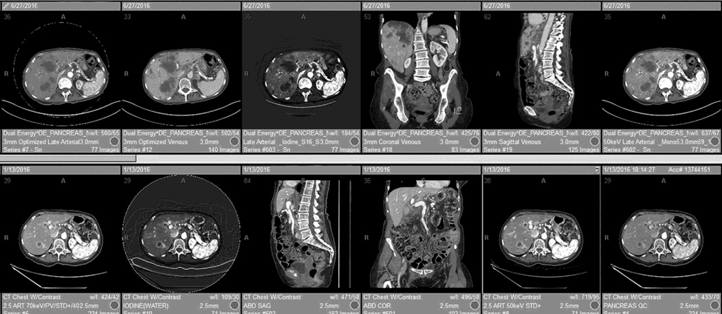
One of the challenges of dual energy imaging is managing the number of series that are created. We have found the most efficient approach is the use of automated hanging protocols/layouts for the reading workstation (Fig.8).
Fig. 8.
An automated reading layout, or “hanging protocol,” for DSDECT (top row) and RSDECT (bottom row). Placed first is the 100–120kVp "workhorse" equivalent series (for the dual energy pancreatic parenchymal phase) and axial portal venous images (combined in the case of the RSDECT platform), followed by a high contrast series (50keV or iodine) and then portal venous multiplanar reconstructions. Coronal and portal venous phase, non-DECT are useful for evaluating for vascular involvement, and peritoneal disease, and are helpful for showing extent of disease at multidisciplinary conference. Lesser used series, such as localizer radiographs, dose injector information, radiation dose documentation, and thin section archival image series can be “pushed” to the end list of displayed series.
A suggested order of the series in a layout would be as follows (Fig. 8): first the “workhorse” 100–120kVp surrogate and portal venous phase axial images, followed immediately by one or more high contrast series, and then coronal and sagittal portal venous phase reconstructions (Fig. 8). We push to the end of the reading pane display/list the least used series such as archived thin section source images, localizer radiographs, injector information, radiation dose values, etc.
Overall, we use pancreatic parenchymal phase images to provide information regarding where tumor is located within the pancreas and its extent, to enhance detectability of hypervascular liver metastases (in the setting of neuroendocrine tumors), to identify enhancing nodules within cystic lesions, and to evaluate arterial vascular anatomy (such as hepatic artery variants). High contrast series are particularly helpful for improving detectability of tumor. Portal venous phase axial images and the portal venous phase coronal and sagittal reconstructions are used to provide information regarding vascular involvement by tumor, and metastatic involvement of the liver, nodes and peritoneum. Our surgeons find coronal portal venous phase reconstructions particularly helpful given it mirrors more closely the surgeon’s intraoperative perspective and patients appear to be most familiar with this anatomic orientation
Interpreting Rapid Switching Images
For studies performed with the rapid switching approach (RSDECT), the 2.5 mm late arterial phase 70 keV are the “workhorse” dual energy images and can be reconstructed at the scanner into the same series as the 2.5 mm portal venous phase non-dual-energy images. This decreases the number of “windows” needed to view the study and the reader can scroll from one phase of imaging directly to another. In our anecdotal experience, this combined series is typically utilized for the majority of interpretations. The 140kVp QC series can be utilized as a supplement for problem solving. The iodine, or 50 keV images are utilized as the “high contrast” series. Some readers prefer the iodine(-water) images as the high contrast images, while others prefer 50keV. Readers can modify which high contrast series they prefer to see most prominently by customizing their hanging protocol. The non-dual energy portal venous phase mutiplanar images (axial, coronal, and sagittal) are used in the conventional manner and for the purposes already described.
Interpreting Dual Source Images
The approach is similar when utilizing images produced on the dual source platform (Fig. 8). One notable exception is that on this platform, the late arterial and portal venous acquisitions are placed into separate series (it is not possible to automatically combine these series). The “workhorse” series used for primary interpretation are the 3 mm polychromatic blended (100–120 kVp equivalent) axial images late arterial phase images and the separate axial 3mm portal venous phase images. As for the rapid switching platform, either the iodine or 50 keV high contrast images are used as the high contrast series to improve visualization of the primary tumor. Again, the user can modify their hanging protocol to their particular preference. The non-dual energy, conventionally acquired portal venous phase images and the coronal and sagittal portal venous reconstructions are used in the same manner as those acquired on the rapid switching platform.
Using this approach, for each platform, the need to go to a workstation application is minimized.
Conclusion
The recent development of dual-energy imaging offers several potential benefits. However, in order to incorporate this new technology efficiently, consideration must be made for designing effective imaging protocols, robust workflows for generation of the unique images available with dual-energy CT, and efficient approaches to image display and interpretation on a PACS reading station. Many different approaches are available. At our own institution, the ability to generate many of these images automatically at the scanner with automatic transmission to a centralized PACS, and the use of PACS workstation automated hanging layouts allow for primary interpretation to remain at the PACS reading station and minimizes the need to utilize vendor specific workstation or application software.
Acknowledgments
This paper did not receive funding support.
Footnotes
Eric P. Tamm, Mail: Diagnostic Radiology, Unit 1473, University of Texas MD Anderson Cancer Center, PO Box 3014012, Houston, TX 77230-1402
Ott Le, Mail to: Diagnostic Radiology, Unit 1473, University of Texas, MD Anderson Cancer Center, PO Box 3014012, Houston, TX 77230-1402
Xinming Liu, Mail to: Division of Imaging Physics, Unit 1472, University of Texas, MD Anderson Cancer Center, PO Box 3014012, Houston, TX 77230-1402
Rick R. Layman, Mail to: Division of Imaging Physics, Unit 1472, University of Texas, MD Anderson Cancer Center, PO Box 3014012, Houston, TX 77230-1402
Dianna D. Cody, Mail to: Division of Imaging Physics, Unit 1472, University of Texas, MD Anderson Cancer Center, PO Box 3014012, Houston, TX 77230-1402
Priya R. Bhosale, Mail to: Diagnostic Radiology, Unit 1473, University of Texas, MD Anderson Cancer Center, PO Box 3014012, Houston, TX 77230-1402
Eric P. Tamm, Conflict of Interest: General Electric healthcare “in kind” research support.
Dianna D. Cody, Conflict of Interest: General Electric healthcare “in kind” research support. Philips Healthcare scientific advisory board. ACR CT accreditation reviewer.
Compliance with Ethical Standards
This is a review article. Therefore no research was performed with animal or human participants.
Contributor Information
Eric P. Tamm, Dept. of Diagnostic Radiology, Division of Diagnostic Imaging, University of Texas, MD Anderson Cancer Center, Houston, Texas, Tel: 713-745-3231, Fax: 713-745-1302
Ott Le, Dept. of Diagnostic Radiology, Division of Diagnostic Imaging, MD Anderson Cancer Center.
Xinming Liu, Division of Imaging Physics, University of Texas, MD Anderson Cancer Center.
Rick R. Layman, Division of Imaging Physics, University of Texas, MD Anderson Cancer Center
Dianna D. Cody, Division of Imaging Physics, University of Texas, MD Anderson Cancer Center
Priya R. Bhosale, Dept. of Diagnostic Radiology, Division of Diagnostic Imaging, MD Anderson Cancer Center
References
- 1.Shuman WP, Green DE, Busey JM, et al. Dual-Energy Liver CT: Effect of Monochromatic Imaging on Lesion Detection, Conspicuity, and Contrast-to-Noise Ratio of Hypervascular Lesions on Late Arterial Phase. AJR Am J Roentgenol. 2014;203:601–606. doi: 10.2214/AJR.13.11337. [DOI] [PubMed] [Google Scholar]
- 2.Patel BN, Thomas JV, Lockhart ME, et al. Single-source dual-energy spectral multidetector CT of pancreatic adenocarcinoma: optimization of energy level viewing significantly increases lesion contrast. Clin Radiol. 2013;68:148–154. doi: 10.1016/j.crad.2012.06.108. [DOI] [PubMed] [Google Scholar]
- 3.Bhosale P, Le O, Balachandran A, et al. Quantitative and Qualitative Comparison of Single-Source Dual-Energy Computed Tomography and 120-kVp Computed Tomography for the Assessment of Pancreatic Ductal Adenocarcinoma. J Comput Assist Tomogr. 2015;39:907–913. doi: 10.1097/RCT.0000000000000295. [DOI] [PMC free article] [PubMed] [Google Scholar]
- 4.Lin XZ, Wu ZY, Tao R, et al. Dual energy spectral CT imaging of insulinoma-Value in preoperative diagnosis compared with conventional multi-detector CT. Eur J Radiol. 2012;81:2487–2494. doi: 10.1016/j.ejrad.2011.10.028. [DOI] [PubMed] [Google Scholar]
- 5.Apfaltrer P, Sudarski S, Schneider D, et al. Value of monoenergetic low-kV dual energy CT datasets for improved image quality of CT pulmonary angiography. Eur J Radiol. 2014;83:322–328. doi: 10.1016/j.ejrad.2013.11.005. [DOI] [PubMed] [Google Scholar]
- 6.Meier A, Wurnig M, Desbiolles L, et al. Advanced virtual monoenergetic images: improving the contrast of dual-energy CT pulmonary angiography. Clin Radiol. 2015;70:1244–1251. doi: 10.1016/j.crad.2015.06.094. [DOI] [PubMed] [Google Scholar]
- 7.De Cecco CN, Muscogiuri G, Schoepf UJ, et al. Virtual unenhanced imaging of the liver with third-generation dual-source dual-energy CT and advanced modeled iterative reconstruction. Eur J Radiol. 2016;85:1257–1264. doi: 10.1016/j.ejrad.2016.04.012. [DOI] [PubMed] [Google Scholar]
- 8.Finkenstaedt T, Manoliou A, Toniolo M, et al. Gouty arthritis: the diagnostic and therapeutic impact of dual-energy CT. Eur Radiol. 2016 doi: 10.1007/s00330-016-4237-2. [DOI] [PubMed] [Google Scholar]
- 9.Korn A, Bender B, Thomas C, et al. Dual energy CTA of the carotid bifurcation: advantage of plaque subtraction for assessment of grade of the stenosis and morphology. Eur J Radiol. 2011;80:e120–e125. doi: 10.1016/j.ejrad.2010.08.028. [DOI] [PubMed] [Google Scholar]
- 10.Johnson TR. Dual-energy CT: general principles. AJR Am J Roentgenol. 2012;199:S3–S8. doi: 10.2214/AJR.12.9116. [DOI] [PubMed] [Google Scholar]
- 11.Marin D, Boll DT, Mileto A, et al. State of the art: dual-energy CT of the abdomen. Radiology. 2014;271:327–342. doi: 10.1148/radiol.14131480. [DOI] [PubMed] [Google Scholar]
- 12.Silva AC, Morse BG, Hara AK, et al. Dual-energy (spectral) CT: applications in abdominal imaging. Radiographics : a review publication of the Radiological Society of North America, Inc. 2011;31:1031–1046. doi: 10.1148/rg.314105159. discussion 1047–1050. [DOI] [PubMed] [Google Scholar]
- 13.Morgan DE. Dual-energy CT of the abdomen. Abdom Imaging. 2014;39:108–134. doi: 10.1007/s00261-013-0033-5. [DOI] [PubMed] [Google Scholar]
- 14.Megibow AJ, Sahani D. Best practice: implementation and use of abdominal dual-energy CT in routine patient care. AJR Am J Roentgenol. 2012;199:S71–S77. doi: 10.2214/AJR.12.9074. [DOI] [PubMed] [Google Scholar]
- 15.Ascenti G, Krauss B, Mazziotti S, et al. Dual-energy Computed Tomography (DECT) in Renal Masses: Nonlinear versus Linear Blending. Academic radiology. 2012 doi: 10.1016/j.acra.2012.05.010. [DOI] [PubMed] [Google Scholar]
- 16.Mileto A, Ramirez-Giraldo JC, Marin D, et al. Nonlinear image blending for dual-energy MDCT of the abdomen: can image quality be preserved if the contrast medium dose is reduced? AJR Am J Roentgenol. 2014;203:838–845. doi: 10.2214/AJR.13.12179. [DOI] [PubMed] [Google Scholar]
- 17.Apel A, Fletcher JG, Fidler JL, et al. Pilot multi-reader study demonstrating potential for dose reduction in dual energy hepatic CT using non-linear blending of mixed kV image datasets. European radiology. 2011;21:644–652. doi: 10.1007/s00330-010-1947-8. [DOI] [PubMed] [Google Scholar]
- 18.Hardie AD, Picard MM, Camp ER, et al. Application of an Advanced Image-Based Virtual Monoenergetic Reconstruction of Dual Source Dual-Energy CT Data at Low keV Increases Image Quality for Routine Pancreas Imaging. J Comput Assist Tomogr. 2015;39:716–720. doi: 10.1097/RCT.0000000000000276. [DOI] [PubMed] [Google Scholar]
- 19.Albrecht MH, Scholtz JE, Kraft J, et al. Assessment of an Advanced Monoenergetic Reconstruction Technique in Dual-Energy Computed Tomography of Head and Neck Cancer. Eur Radiol. 2015;25:2493–2501. doi: 10.1007/s00330-015-3627-1. [DOI] [PubMed] [Google Scholar]
- 20.Matsumoto K, Jinzaki M, Tanami Y, et al. Virtual monochromatic spectral imaging with fast kilovoltage switching: improved image quality as compared with that obtained with conventional 120-kVp CT. Radiology. 2011;259:257–262. doi: 10.1148/radiol.11100978. [DOI] [PubMed] [Google Scholar]
- 21.McCollough CH, Leng S, Yu L, et al. Dual- and Multi-Energy CT: Principles, Technical Approaches, and Clinical Applications. Radiology. 2015;276:637–653. doi: 10.1148/radiol.2015142631. [DOI] [PMC free article] [PubMed] [Google Scholar]
- 22.Chai Y, Xing J, Gao J, et al. Feasibility of virtual nonenhanced images derived from single-source fast kVp-switching dual-energy CT in evaluating gastric tumors. Eur J Radiol. 2016;85:366–372. doi: 10.1016/j.ejrad.2015.11.015. [DOI] [PubMed] [Google Scholar]
- 23.Song I, Yi JG, Park JH, et al. Virtual Non-Contrast CT Using Dual-Energy Spectral CT: Feasibility of Coronary Artery Calcium Scoring. Korean J Radiol. 2016;17:321–329. doi: 10.3348/kjr.2016.17.3.321. [DOI] [PMC free article] [PubMed] [Google Scholar]
- 24.Glazer DI, Maturen KE, Kaza RK, et al. Adrenal Incidentaloma Triage With Single-Source (Fast-Kilovoltage Switch) Dual-Energy CT. AJR Am J Roentgenol. 2014;203:329–335. doi: 10.2214/AJR.13.11811. [DOI] [PMC free article] [PubMed] [Google Scholar]
- 25.Mileto A, Nelson RC, Marin D, et al. Dual-energy multidetector CT for the characterization of incidental adrenal nodules: diagnostic performance of contrast-enhanced material density analysis. Radiology. 2015;274:445–454. doi: 10.1148/radiol.14140876. [DOI] [PubMed] [Google Scholar]
- 26.Ascenti G, Mileto A, Krauss B, et al. Distinguishing enhancing from nonenhancing renal masses with dual-source dual-energy CT: iodine quantification versus standard enhancement measurements. Eur Radiol. 2013;23:2288–2295. doi: 10.1007/s00330-013-2811-4. [DOI] [PubMed] [Google Scholar]
- 27.Albrecht MH, Scholtz JE, Husers K, et al. Advanced image-based virtual monoenergetic dual-energy CT angiography of the abdomen: optimization of kiloelectron volt settings to improve image contrast. Eur Radiol. 2015 doi: 10.1007/s00330-015-3970-2. [DOI] [PubMed] [Google Scholar]
- 28.van Elmpt W, Landry G, Das M, et al. Dual energy CT in radiotherapy: Current applications and future outlook. Radiother Oncol. 2016;119:137–144. doi: 10.1016/j.radonc.2016.02.026. [DOI] [PubMed] [Google Scholar]
- 29.Carrascosa P, Capunay C, Rodriguez-Granillo GA, et al. Substantial iodine volume load reduction in CT angiography with dual-energy imaging: insights from a pilot randomized study. Int J Cardiovasc Imaging. 2014 doi: 10.1007/s10554-014-0501-1. [DOI] [PubMed] [Google Scholar]
- 30.Bongartz T, Glazebrook KN, Kavros SJ, et al. Dual-energy CT for the diagnosis of gout: an accuracy and diagnostic yield study. Ann Rheum Dis. 2015;74:1072–1077. doi: 10.1136/annrheumdis-2013-205095. [DOI] [PMC free article] [PubMed] [Google Scholar]
- 31.Frellesen C, Fessler F, Hardie AD, et al. Dual-energy CT of the pancreas: improved carcinoma-to-pancreas contrast with a noise-optimized monoenergetic reconstruction algorithm. Eur J Radiol. 2015;84:2052–2058. doi: 10.1016/j.ejrad.2015.07.020. [DOI] [PubMed] [Google Scholar]
- 32.McNamara MM, Little MD, Alexander LF, et al. Multireader evaluation of lesion conspicuity in small pancreatic adenocarcinomas: complimentary value of iodine material density and low keV simulated monoenergetic images using multiphasic rapid kVp-switching dual energy CT. Abdom Imaging. 2015;40:1230–1240. doi: 10.1007/s00261-014-0274-y. [DOI] [PubMed] [Google Scholar]
- 33.Therasse P, Arbuck SG, Eisenhauer EA, et al. New guidelines to evaluate the response to treatment in solid tumors. European Organization for Research and Treatment of Cancer, National Cancer Institute of the United States, National Cancer Institute of Canada. J Natl Cancer Inst. 2000;92:205–216. doi: 10.1093/jnci/92.3.205. [DOI] [PubMed] [Google Scholar]
- 34.Schwartz LH, Litiere S, de Vries E, et al. RECIST 1.1-Update and clarification: From the RECIST committee. Eur J Cancer. 2016;62:132–137. doi: 10.1016/j.ejca.2016.03.081. [DOI] [PMC free article] [PubMed] [Google Scholar]
- 35.Miller AB, Hoogstraten B, Staquet M, et al. Reporting results of cancer treatment. Cancer. 1981;47:207–214. doi: 10.1002/1097-0142(19810101)47:1<207::aid-cncr2820470134>3.0.co;2-6. [DOI] [PubMed] [Google Scholar]
- 36.Wichmann JL, Hardie AD, Schoepf UJ, et al. Single- and dual-energy CT of the abdomen: comparison of radiation dose and image quality of 2nd and 3rd generation dual-source CT. Eur Radiol. 2016 doi: 10.1007/s00330-016-4383-6. [DOI] [PubMed] [Google Scholar]


