Abstract
There is a need to better understand the effects of intervertebral spacer material and design on the stress distribution in vertebral bodies and endplates to help reduce complications such as subsidence and improve outcomes following lumbar interbody fusion. The main objective of this study was to investigate the effects of spacer material on the stress and strain in the lumbar spine after interbody fusion with posterior instrumentation. A standard spacer was also compared with a custom-fit spacer, which conformed to the vertebral endplates, to determine if a custom fit would reduce stress on the endplates. A finite element (FE) model of the L4–L5 motion segment was developed from computed tomography (CT) images of a cadaveric lumbar spine. An interbody spacer, pedicle screws, and posterior rods were incorporated into the image-based model. The model was loaded in axial compression, and strain and stress were determined in the vertebra, spacer, and rods. Polyetheretherketone (PEEK), titanium, poly(para-phenylene) (PPP), and porous PPP (70% by volume) were used as the spacer material to quantify the effects on stress and strain in the system. Experimental testing of a cadaveric specimen was used to validate the model's results. There were no large differences in stress levels (<3%) at the bone–spacer interfaces and the rods when PEEK was used instead of titanium. Use of the porous PPP spacer produced an 8–15% decrease of stress at the bone–spacer interfaces and posterior rods. The custom-shaped spacer significantly decreased (>37%) the stress at the bone–spacer interfaces for all materials tested. A 28% decrease in stress was found in the posterior rods with the custom spacer. Of all the spacer materials tested with the custom spacer design, 70% porous PPP resulted in the lowest stress at the bone–spacer interfaces. The results show the potential for more compliant materials to reduce stress on the vertebral endplates postsurgery. The custom spacer provided a greater contact area between the spacer and bone, which distributed the stress more evenly, highlighting a possible strategy to decrease the risk of subsidence.
Introduction
Low back pain is problematic worldwide, causing daily discomfort and restriction of activities. It is estimated that as much as 80% of the population will experience back pain during their lifetime [1]. Back pain is one of the most common reasons for missed work, and it is the second most common reason for visits to the doctor's office [2]. Arthritis, poor posture, obesity, and psychological stress are all factors in increasing the risk of back pain [2]. Degenerative disk disease (DDD) is a common reason for low back pain, and it occurs when the disk begins to degenerate and collapse, causing pain. Though this can be caused by injury or trauma, such as a car accident, it is commonly an age-related, progressive degenerative process [3].
Lumbar spinal fusion is a surgical solution for patients with extreme pain or instability refractory to conservative care. The aim of the surgery is to fuse two adjacent vertebrae into a single unit by stimulating bone growth. An interbody spacer, or spinal cage, is used to provide a fixed space between the vertebrae and bone graft is used in the process to stimulate bone growth between the two vertebrae, eliminating motion in that segment. Posterior instrumentation, such as titanium screws and rods, may be used to fixate the spinal unit during the healing process to restore intervertebral height and provide stability.
Subsidence occurs when the spacer penetrates the vertebral endplate and intrudes into the vertebral body following surgery, leading to misalignment and reduced intervertebral height. In one previous study, five incidences (15.6%) of subsidence out of 32 procedures of anterior lumbar interbody fusion (ALIF) using a polyetheretherketone (PEEK) spacer were found [4]. In another study of 122 PEEK spacers used in transforaminal lumbar interbody fusion, 18 (14.8%) subsided more than 2 mm into the adjacent vertebral body [5]. Another study that monitored disk space heights before, immediately after, and months after ALIF with bone graft spacers found that 100% of the 31 patients developed disk space height decreases during the postoperative period, with 46% having narrower levels than the preoperative height [6,7]. McClellen et al. [8] reported 16% of lumbar levels had evidence of graft subsidence [9].
Spacers with increased stiffness values could lead to higher stresses on the bone, possibly leading to subsidence and the need for reoperation. The stiffness of PEEK and titanium, two of the most common implant materials, can be orders of magnitude stiffer than the overall structure of the underlying vertebral endplates. Material stiffness can be described using Young's modulus (E), which dictates the amount a material will deform under a given stress. Titanium alloys typically have an E of 110,000 MPa, PEEK has an E of ranging approximately between 2000 and 4000 MPa depending on its crystallinity [10,11], and the trabecular bone supporting the thin cortical shell of the endplates has an E ranging from 20 to 1080 MPa [12]. Vadapalli et al. [13] studied the effects of spacer stiffness in a L3–L5 segment with L4–L5 fusion with posterior instrumentation. Peak von Mises stress (distortional stress) in the endplates increased by 2.4-fold or greater with a titanium spacer versus PEEK. This study suggested that the chance of subsidence would be less with PEEK spacers and that the lower stiffness of PEEK did not affect stability. The concept of an interbody cage with soft layers (E = 19 MPa) on the bone–implant interface was tested in a finite element study of an L4–L5 segment [14]. The study showed that the peak contact pressure was significantly reduced with this cage, which could be a strategy for decreasing the risk of cage subsidence [14].
This study addresses the effects of the spacer material and design on the stress and strain in the bone and posterior instrumentation. Using a finite element model of the L4–L5 motion segment, we compared titanium, PEEK, poly(para-phenylene) (PPP), and PPP with 70% porosity as the spacer material. Additionally, a spacer designed to conform to the vertebral endplates could potentially evenly distribute and reduce the overall stress at the endplates. Such spacers could be manufactured by computer numerically controlled (CNC) milling or 3D printing.
The purpose of this study was to use an L4–L5 model of lumbar spine fusion with posterior instrumentation to quantify differences in stress in the lumbar spine using different spacer materials. The resulting data may provide a quantitative rationale for the use of specific implant materials and instrumentation on a patient-specific basis. Based on preliminary work [15,16], it was hypothesized that a spacer with a modulus closer to that of the bony endplate would shift the load from the spacer and bone to the posterior rods. Furthermore, we hypothesized that a less stiff spacer would reduce stress at the bone–spacer interfaces and that a spacer that conformed to the contours of the vertebral endplates would distribute the stresses more evenly, decreasing the stress at the bone–spacer interfaces.
Materials and Methods
Model Preparation.
A 3D linear finite element (FE) model of the L4 and L5 vertebrae was developed from computed tomography (CT) data of a cadaveric lumbar spine. The donor was a 70-yr-old male who died from respiratory failure and sepsis.
Imaging was performed on a Gemini TF 64 CT system (Philips, Amsterdam, The Netherlands) with settings of 120 kVp, 290 mAs, and voxel size = 0.7 × 0.7 × 0.9 mm. The images were imported into scanip (Simpleware, Ltd., Exeter, UK) for model development. The L4–L5 motion unit was segmented from the images using a threshold-driven region growing algorithm with manual correction where needed. An ALIF interbody spacer and posterior instrumentation (pedicle screws and 5.5-mm diameter rods) were created using solidworks (Dassault Systèmes, Waltham, MA) and then integrated into the model using simpleware's + cad module. The spacer was positioned between the inferior surface of L4 and superior surface of L5.
Polyurethane blocks were incorporated into the model to depict the mechanical testing setup used for model validation (see “Experimental Methods” section). In addition to recreating the experimental setup, the polyurethane blocks help to distribute the applied loads evenly across the superior and inferior bone surfaces in the model. Facet joints, including thin cartilage layers, were included in the model and assigned as a contact pair. A contact pair was also assigned between L4 and the spacer and L5 and the spacer. The entire assembly was then meshed with linear, four-node tetrahedral elements using the adaptive meshing algorithm in simpleware's + fe module (Fig. 1). An outer layer of shell elements was added to each vertebra in abaqus (Dassault Systèmes, Waltham, MA) to simulate the thin vertebral cortex. The assembled model represents the condition immediately following surgery. A model with a custom fit ALIF spacer was also created in simpleware. The spacer was developed to conform to the curvature of the endplates to help evenly distribute the stress along the bone–spacer interface (Fig. 2).
Fig. 1.
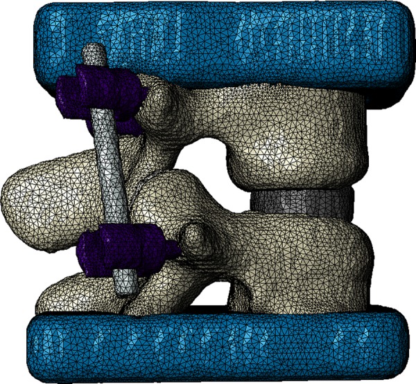
Meshed model with CAD-developed spacer, posterior instrumentation (pedicle screws and rods), and urethane loading blocks
Fig. 2.
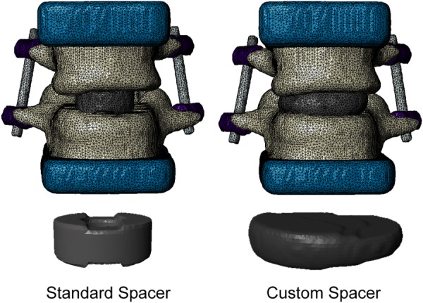
Comparison of standard spacer and custom fit spacer in the model
Material Properties.
Homogeneous material properties were used for the trabecular core and the cortical shell of the vertebrae. The cortical bone was assigned an elastic modulus (E) of 12 GPa and Poisson's ratio (υ) of 0.3 [17]. Due to the relatively low resolution provided by the clinical CT protocol used to obtain the images, the cortical shell could not be directly defined based on image data. Instead, the cortical shell thickness to be used in the model was determined by fitting a linear relationship between age and cortical thickness. Mosekilde [18] reported a range of cortical thickness values in the vertebral body for age ranges 20–40 and 70–80 yr. Using the linear fit equation to this data, a cortical thickness of 0.27 mm was computed for the 70-yr-old male donor, and this thickness was assigned to shell elements used to simulate the cortex in the final model. Based on a study of volumetric bone mineral density (vBMD) of the lumbar spine in 323 men [19] and linear relationship between trabecular vBMD and E [20], an E of 400 MPa and Poisson's ratio (υ) of 0.3) were assigned to the trabecular bone filling the interior of the vertebral bodies in the model.
The rods and screws were treated as titanium with an E of 110 GPa and υ of 0.3 [17]. The blocks were assigned an E of 6832 MPa and a υ of 0.3 (manufacturer's data). Cartilage-lined facet joints were included in the model, and cartilage regions were assigned an E of 6 MPa and a υ of 0.49 [21]. Multiple material properties were used to determine the effects of spacer stiffness on stress distribution (Table 1). Titanium and PEEK are current materials used for interbody spacers in lumbar spine fusion. PPP is a polymer with similar mechanical properties to PEEK, but PPP can be manufactured with a prescribed porosity and has potential for use in orthopedic applications [24]. Porous PPP can be manufactured via hot press sintering of PPP powder with the desired amount of salt (NaCl) crystals needed to produce the desired level of porosity. After sintering, the salt is leached out, leaving an open-cell foam structure with a pore size dictated by the size of the NaCl crystals [25]. For the models in this study, PPP was simulated with 70% porosity by calculating the apparent elastic modulus of the porous PPP (Eq. (1)) using
Table 1.
| Spacer material | Porosity | Elastic modulus (MPa) | Poisson's ratio |
|---|---|---|---|
| Titanium | None | 110,000 | 0.3 |
| PEEK | None | 4000 | 0.36 |
| PPP | None | 5000 | 0.3 |
| 70% | 450 |
| (1) |
where is the modulus of the solid material, is the elastic modulus of the porous material, and f is the porosity [25–27]. Based on this relationship, PPP with 70% porosity was assigned an elastic modulus of 450 MPa, which falls within the range measured experimentally [24].
Finite Element Analysis.
Finite element analysis was performed using abaqus. All elements in the model were C3D4 (linear four-node tetrahedral) elements. The pedicle screws were bonded to the vertebral bone (i.e., all nodes at the interface between the screws and bones were shared between the two different sections). Contact pairs were defined between the spacer and vertebral endplates. This allowed nodes in the two different materials, originally at shared locations, to slip parallel to one another under a friction coefficient of 0.1. This provided a simulation of the mechanical situation directly after surgery was performed, prior to the onset of bony fusion. All three degrees-of-freedom for each node on the inferior surface of the urethane block attached to L5 were fixed, and a static, compressive force of 730 N was applied evenly across surface of the superior urethane block. The force was applied as a pressure with a magnitude equal to 730 N divided by the area of the block's superior surface. The load of 730 N was chosen based on the peak in vivo force in the lumbar spine of a patient rising from a chair, available in the orthoload database1 [28,29]. Groups of elements were selected at the L4 and L5 anterior regions, anterior spacer region, posterior rods region, and in the bone tissue at the bone–implant interface of L4 and L5 for analysis of stress. The von Mises (distortional) stress was recorded for elements in each of these locations to evaluate the load distribution in the model, and strains were recorded for comparison with experimental measurements. A mesh convergence study was conducted to determine the appropriate mesh density for the finite element model. Starting with a mesh size containing 26,593 nodes, the mesh was refined until convergence was obtained. Mesh convergence was determined by measuring the overall stiffness of the model (applied force/displacement of the top surface of the urethane block) at each mesh size until the change in stiffness was less than 2%.
Experimental Methods.
Mechanical testing of the cadaver specimen was conducted, and the experimental data were compared with the results obtained from the FE models. After imaging the cadaveric spine, the L4–L5 motion segment was excised. A spine surgeon (VVP) inserted a spacer, screws, and rods into the cadaver specimen. The L4 superior endplate and the L5 inferior endplate were then potted in urethane (Dyna-cast, Kindt-Collins Company, Cleveland, OH). The L4–L5 segment with interbody spacer and posterior instrumentation was placed in compression in an MTS Insight 30 (MTS, Eden Prairie, MN) with a 30 kN load cell (Fig. 3). Strain rosettes (L2A-06-062WW-350, Vishay Micro-Measurements, Raleigh, NC) and uniaxial strain gages (L2A-06-125LW-120, Vishay Micro-Measurements, Raleigh, NC) were used to record strains during loading. Strain rosettes were placed on the anterior surface of the spacer and anterior surface of the L4 vertebra, and uniaxial strain gages were placed on the posterior sides of the rods (Fig. 4). The motion segment was tested in compression at room temperature with three different peak loads (400, 730, and 1000 N). Specimens were kept hydrated with saline solution throughout testing. During each trial (three per peak load level), the applied load was increased under displacement control until the predetermined peak load was reached. When the peak load was reached, the compression platens were held in place for two minutes. The peak principal strains that occurred on the anterior surfaces of the spacer and L4 vertebral body were calculated from rosettes, and the peak strains on the posterior surfaces of the rods were measured from the uniaxial gages.
Fig. 3.
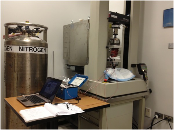
Experimental setup. Compressive loads were applied to the L4–L5 unit via compression platens with the proximal and distal ends potted in urethane blocks. Strains were measured during loading using a strain recorder and stored on a PC for analysis.
Fig. 4.

Locations of strain gages used in experimental tests. Anterior view of L4–L5 unit with locations of strain rosettes at the spacer and L4 vertebral body (left). Posterior view of L4–L5 unit with location of uniaxial strain gages at the rods (right).
Results
Mesh Convergence.
The overall stiffness of the model converged to less than a 2% difference from 93,790 nodes to 252,357 nodes (Fig. 5). There was also less than a 2% difference in stiffness between models with 93,790 nodes and 377,542 nodes. Based on these results, the mesh containing 93,790 nodes was used in the remainder of the study.
Fig. 5.
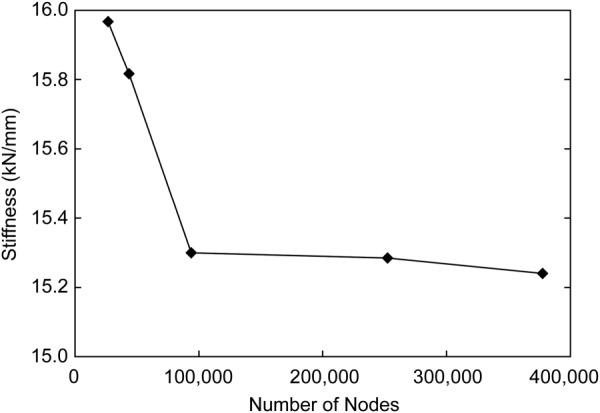
Mesh convergence results for L4–L5 model stiffness. Differences in overall model stiffness converged to less than 2% at a mesh density of 93,790 nodes.
Comparison With Experiments.
The measured experimental strain and the FE model strain at each location were normalized to the corresponding peak load, and linear regression was performed between the FE-predicted strains and the experimental strains [30]. The resulting regression equation was y = 1.02x + 0.18 με/N (r2 = 0.56, p < 0.001), where x is the normalized FE-predicted strain, and y is the normalized experimental strain. Thus, the model had the ability to explain 56% of the variance in measured strain. While the coefficient of determination was rather modest due to the relatively small number of analyzed locations, the relationship was highly significant (p < 0.001), and the slope was very close to 1, suggesting that the model provided a reasonable depiction of strain distribution and variation.
Effects of Spacer Material on Stress Magnitude and Distribution.
The stresses within the components of the fusion construct for the standard spacer using the four materials of this study are shown in the box-and-whisker plots in Fig. 6. On average, the model experienced 6–12% less distortional stress in the bone–spacer interface locations and at the anterior surface of the spacer when using 70% porous PPP compared to the other spacer materials. Conversely, using the porous spacer lead to an increase in stress at the anterior surfaces of the vertebral bodies and on the posterior surfaces of the rods. Stress at the bone–spacer interfaces was highest when using a titanium spacer. However, PEEK and solid PPP only decreased the stress in these locations by 3% or less. Stress increased at the anterior surface of L4 as the stiffness of the spacer decreased. The model demonstrated more than 12 times greater stress at the L4 anterior location than the L5 anterior location. This result is likely due to the different geometries of the two vertebral bodies: the anterior surface of the L5 vertebra in the model had a higher degree of curvature than the same surface of the L4 vertebra (see Fig. 1). The bone–spacer interfaces experienced an average stress less than 1 MPa for all spacer materials, while the stress in the rods was in the range of 40 MPa.
Fig. 6.
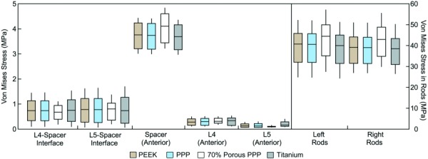
Box-and whisker plots of stress distribution in each region of the model under a compressive load of 730 N using the standard spacer. Horizontal lines represent the median stress in each region; boxes extend from the lower quartile to the upper quartile of all stress values in the region; whiskers indicate the maximum and minimum stress in the region. The stresses for bone–spacer interfaces include the entire region of contact between the endplates and spacer surfaces. Other regions correspond to the measurement locations used in mechanical tests (see Fig. 3), with the addition of an L5 anterior location analogous to that used for L4. The stress in the posterior rods (to the right of the dashed line) is plotted on a separate scale due to the higher stress magnitudes.
The effects of the custom fit spacer compared to the standard spacer were also investigated at the bone–spacer interfaces and rods. The bone–spacer interfaces experienced higher stress with the standard spacer compared to the custom spacer with all materials (Fig. 7). The custom spacer provided a 37–41% decrease in mean stress at the L4 bone–spacer interface compared to the original spacer for each material and a range of 51–54% at the L5 bone–spacer interface. The L4 and L5 bone–spacer interfaces experienced a 9% and 1% decrease in mean stress, respectively, with the 70% porous PPP custom spacer compared to the solid PPP custom spacer (L4: 0.473 MPa versus 0.431 MPa; L5: 0.386 MPa versus 0.382 MPa) (Fig. 7). Similar comparisons were seen between 70% porous PPP and both PEEK and titanium. A visual representation of the stress distribution on the L5 endplate for the standard and custom spacers is provided in Fig. 8. A larger footprint of relatively high stress areas (>1 MPa) can be seen in the posterior half of the endplate when using the standard spacer. This footprint is greatly reduced using the custom spacer. This comparison was representative for all materials tested, as the data shown in Fig. 6 demonstrate. The stresses in the posterior rods were also investigated when comparing the standard and custom spacers (Fig. 9). The mean von Mises stress in the rods decreased by 28–29% when using the custom spacer for all materials.
Fig. 7.
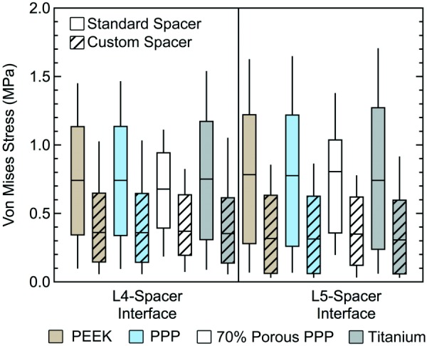
Box-and-whisker plots of endplate stress distributions at the bone–spacer interfaces with the standard and custom spacer
Fig. 8.
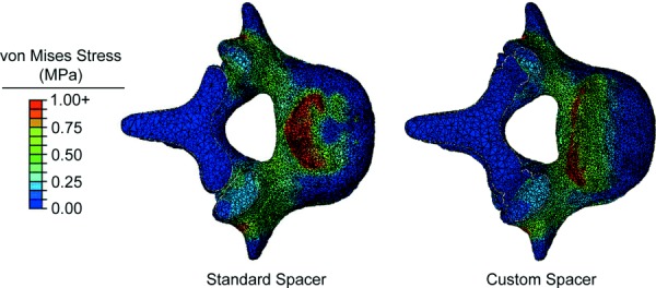
Stress distribution at the L5 bone–spacer interfaces with the 70% porous PPP standard spacer (left) and 70% porous PPP custom spacer (right)
Fig. 9.
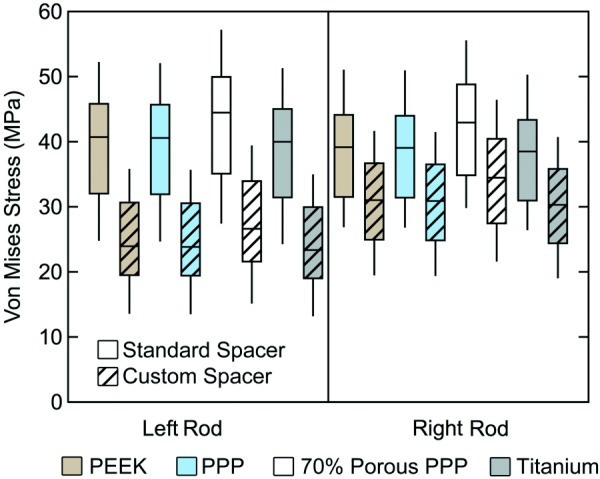
Box-and-whisker plots of the stress distribution in posterior rods with the standard spacer and custom spacer
Discussion
The purpose of this study was to compare the influence of spacer materials with a wide range of elastic moduli and spacer shape on the stress distribution within a L4–L5 fusion. The results of this study demonstrate that distortional stresses on the vertebral endplates can be decreased by using a more compliant spacer material and by using a spacer that conforms to a greater area of the endplate surface. Of the materials tested in the study, the material with the lowest stiffness, 70% porous PPP (E = 450 MPa), resulted in the lowest stress at the endplates after simulated lumbar interbody fusion with posterior instrumentation (6–9% less than the PEEK and 8–12% less than the titanium). Minimal differences occurred with other materials tested, despite the large differences in stiffness between titanium (E = 110,000 MPa), solid PEEK (E = 4000 MPa), and solid PPP (E = 5000 MPa). Overall, the greatest stress experienced in the L4–L5 model was in the rods. The stress experienced in the rods was more than 40 times greater than the stress experienced at the bone–spacer interfaces. As hypothesized, the stress in the rods was greatest with a spacer made of 70% porous PPP, demonstrating a shift in load due to the more compliant spacer material being compressed between the vertebral bodies. Similarly, stress on the anterior surfaces of the vertebral bodies was highest when using the 70% porous PPP, due to the higher amount of spacer deformation shifting the load distribution. The custom spacer, which had a larger cross-sectional area and conformed to a relatively large area of the endplates, reduced both endplate stresses and stresses in the posterior instrumentation.
Of particular note is that reductions in stress magnitudes when using PEEK or solid PPP instead of titanium were quite small (3% or less at the bone–spacer interfaces), despite the fact that the two polymers had Young's moduli less than 5% that of titanium. When using 70% porous PPP (approximately 1/10 the stiffness of solid PEEK and PPP), stresses at the bone–spacer interfaces decreased more dramatically (6–12%). Therefore, it appears that solid high-performance polymers, such as PEEK, may be too stiff to effectively decrease the risk of subsidence, whereas using a more compliant, porous spacer may reduce endplate stress more effectively. Porous titanium, another option for future use in interbody spacers, can be manufactured with a Young's modulus as low as 0.6 GPa, depending on strut size and porosity [31]. Overall, our results suggest that a porous spacer with a Young's modulus less than 1 GPa should effectively reduce endplate stresses. Thus, both porous titanium and porous PPP may have the potential to decrease the risk of subsidence.
The drawback to using PPP with a relatively high porosity is that the material's fatigue life is decreased significantly compared to solid PPP. Our laboratory recently showed that 75% porous PPP had an endurance limit (defined as the stress for which failure did not occur after 1 million cycles) of 1.6 MPa when loaded in compression [24]. In our model, using 70% porous PPP (which would be expected to have a slightly higher endurance limit than 75% porous PPP) resulted in stresses of 0.11 MPa and 0.76 MPa at the anterior and inferior surfaces of the spacer, respectively. These stress levels are below the endurance limit for 70% porous PPP under compressive loading, providing a factor of safety of about 2 for a cyclic, compressive load of 730 N applied for 1 million cycles. All of this suggests that, in a successful fusion, it is likely that bone bridging between the two vertebral bodies would relieve stress in the standard spacer well before the spacer undergoes fatigue failure. It should be noted that an ongoing investigation in another laboratory is researching PEEK implants with surface porosity, which might serve to reduce stresses at the interface while maintaining mechanical properties [32].
The custom spacer, designed to conform to the contours of the vertebral endplates, dramatically decreased stress at the bone–spacer interfaces compared to the standard spacer, no matter which material was used (Fig. 7). Additionally, the stress in the rods decreased with the custom spacer for all materials (Fig. 9). These effects are due to the greater surface area of the custom spacer. More of the total load shifts from the rods to the spacer, and this happens without causing greater stress at the bone–spacer interfaces. Also, since the spacer supports more of the anterior endplate, there is less bending of the rods in the sagittal plane. The outcome of the custom spacer analysis showed that a greater contact area between the spacer and bone would distribute the stress more evenly at the bone, reducing stress concentrations due to small contact area and sharp corners on original spacer. A spacer that can distribute the stress more evenly at the bone–spacer interfaces would likely decrease the risk of subsidence. However, the custom design used in this study did not include any holes for including bone graft or allowing bony ingrowth. If manufactured with appropriate pore size, it is possible that a porous PPP spacer would be conducive to bone ingrowth and load sharing while allowing for more evenly distributed stress. This theoretical design successfully demonstrated the value of an increased contact surface area and conforming geometry, but additional design refinements would be needed to create a feasible device for use in the clinic. In particular, inserting such a large-sized spacer during the ALIF procedure would pose challenges, especially considering the need to avoid disturbing vascular structures anterior the vertebral bodies. Thus, while the custom spacer offers theoretical improvements in mechanics after fusion, the proper surgical approach and other practical aspects of implanting such a device must be addressed.
A previous FE study of an interbody cage with soft (low elastic modulus, E = 19 MPa) layers at the bone–implant interface and a stiff inner core (E = 2000 MPa) demonstrated the potential effectiveness of eliminating the sharp corners typically found in interbody spacers and cages while maintaining the stability provided by a stiffer material [14]. The study also evaluated a homogeneous soft cage and found that, for moduli less than 100 MPa, there was ineffective stability. The ranges of motion (ROM) in three anatomical directions were measured to quantify stabilization, and the results showed that there were no differences in ROM with stiffer cages (>1 GPa), which supports the idea that a material as stiff as titanium is not necessary. Overall, the authors' findings showed that the nonhomogeneous cage with soft layers could be effective for reducing subsidence. However, for ease of manufacturing and avoiding the potential for failure at the interfaces between different materials, it may be more desirable to have a spacer that is created from a single material. Our study did not analyze stability directly, but our 70% porous PPP had a modulus of 450 MPa, over four times higher than the identified stability limit of 100 MPa.
Vadapalli et al. investigated the effect of spacer material, specifically PEEK and titanium, on endplate stress and reported a much more noticeable change between materials [13]. The stresses at the endplates increased by 2.4-fold when titanium was used instead of PEEK, and the maximum stress seen was 48 MPa. However, this result occurred for a bending loading condition, while our model focused on axial loading only. Their nonlinear model also contained a 0.5 mm thick cortical shell compared to our 0.27 mm thick shell, used an E of 100 MPa for trabecular bone compared to our 400 MPa, and used a different spacer geometry with bone graft inserted in the middle. Since our model and that of Vadapalli et al. have so many differences, it is difficult to conclude specifically why our model predicted a smaller relative difference between PEEK and titanium spacers. Our study demonstrated a monotonic decrease in endplate stress with decreasing spacer stiffness. Therefore, both our model and the Vadapalli model support the conclusion that more compliant spacer materials will decrease stress in the vertebral endplates.
Interbody cages must be able to withstand strict mechanical testing requirements to gain regulatory clearance (ASTM F2077). As a result, many cages are designed using solid titanium and PEEK components. While these materials are generally good candidates to provide mechanical strength against device failure, they may be overdesigned and might not consider their impact on endplate failure (i.e., subsidence). Our results support the notion that increasing the device–bone interface area will lower average stresses on the endplate and lead to a better distribution of stresses; however, increasing the overall contact area of the device will lower the area and volume for fusion to occur. To address this issue, researchers are proposing the use of porous implants such that bone can grow through the device body. Current work in our laboratory is aimed at determining the extent to which osteoblasts in cell culture and in vivo animal studies can create new bone tissue within the pore space of PPP implants. Preliminary results have been encouraging, suggesting that bony ingrowth from the endplates into the porous structure would serve to stabilize the implant and promote bony fusion.
While the custom spacer in this study was only theoretical, new additive manufacturing and/or computer numerically controlled (CNC) milling techniques could enable the creation of patient-specific cages with a porous architecture. Additive manufacturing, or 3D printing, techniques are currently being developed for fabricating porous polymers [33] and titanium alloys [34] for use in orthopedic applications. A review of patient-specific 3D printing techniques specifically for applications in the spine was recently published by Provaggi et al. [35]. As an alternative to 3D printing, CNC milling can also be used to fabricate custom-fit implants. The use of CNC milling based on 3D images is now commonly used in the creation of patient-specific dental implants and dental crowns [36,37]. Similar techniques could be used to fabricate custom implants using the porous PPP manufactured in our laboratory using hot press sintering and salt leaching.
Our L4–L5 computational modeling results were compared to experimental data. The relationship was statistically significant (p < 0.001), and the model predicted 56% of the variance in the corresponding experimental measurements. Overall, the results of the validation experiment suggest that the model produced a realistic depiction of strain distribution and magnitude in the lumbar spine after interbody fusion with posterior instrumentation. The bone material properties and cortical thickness were applied to the model based on published data, which could contribute to differences from experimental data. Quantitative CT, which provides a 3D map of bone mineral concentration, would likely be useful for producing more accurate, patient-specific models. While the resolution of clinical CT systems prevents direct depiction of much of the thin vertebral cortex, future increases in imaging quality and image processing may provide a more direct means of modeling the cortex.
While our modeling technique provided a means for direct comparisons between different spacer designs and materials, the study had some limitations. For example, ligaments connecting the two vertebrae were not included in the model. However, the stiffness of the posterior rods is so much higher than ligamentous tissue that including the effects of the ligaments would be minimal. Also, the porous PPP model used a continuum approach rather than directly modeling the porous microstructure. Given our focus on macroscale stress distributions, the continuum model was appropriate. Ongoing studies in our laboratory aim to explicitly model the porous structure to investigate the effects of bone ingrowth into the pores of a porous PPP spacer. Only one cadaver specimen was used in this study, but the same image processing and modeling techniques can be used in future studies to evaluate patient-specific differences. The use of a single cadaver specimen also offered an advantage, because multiple cages and materials were tested in the exact same patient. Our results suggested that the model with homogeneous trabecular and cortical material properties sufficiently represented experimental tests. However, a study with multiple cadaver specimens incorporating inhomogeneous, QCT-based bone material properties would provide more patient-specific details in future models. The model also included a perfectly smooth interface between the spacer and vertebral endplates. In reality, the cartilage and mineralized tissues at the endplates are disrupted during surgery, producing a more irregular geometry at this interface. Therefore, the model may not fully capture the heterogeneous stress distribution at locations of bone–spacer contact. Furthermore, the model presented in this study offers only a single snapshot in time, reflecting the distribution of stress directly after implantation of the spacer and posterior instrumentation. Bone is known to remodel over time due to alterations in mechanical loading. Therefore, it is likely that the stress distributions for the different spacer materials and designs observed in this study would diverge over time due to the different alterations of implant stresses. Future simulations that implement time-dependent changes in bone density and geometry may offer insight into the long-term consequences of the implant-specific differences uncovered in this study. Finally, axial compressive loading was the only type of load included in this study, but bending and torsion loads could be added in future studies to more fully characterize the range of stresses expected in different activities. It should be noted that two of the authors of this paper have financial ties to medical device companies: LSC is employed by Mighty Oak Medical, and CMY owns shares of Medshape, Inc. Neither company is currently developing technologies based upon the porous PPP material or custom spacer design investigated in this study, and neither entity contributed funding for the study. Funding for the study was supplied by a grant from NIAMS.
Image-based modeling of the lumbar spine is a valuable tool for evaluating differences in vertebral stress due to implant materials and design, providing a promising noninvasive tool for selection of device materials on a patient-specific basis. The custom fit spacer that was developed in the model to conform to the curvature of the vertebral endplates demonstrated the potential value of patient-specific implant design. With recent advances in and increased availability of additive manufacturing (3D printing), producing patient-specific implants for a reasonable cost may soon become a reality. In conjunction with custom implant design, patient specific, image-based modeling may also provide a means of virtually testing interbody spacers prior to surgery.
Conclusions
The results of this study suggest that materials more compliant than those currently used in the manufacture of interbody spacers may help to reduce the incidence of subsidence. Specifically, 70% porous PPP provide a reduction of stresses in vertebral endplates while maintaining implant stresses below the endurance limit for axial compressive loading. The results also suggest that patient-specific spacer geometry could decrease stresses on posterior instrumentation and reduce stress concentrations in the endplates after lumbar interbody fusion.
Acknowledgment
The research reported in this publication was supported by the National Institute of Arthritis and Musculoskeletal and Skin Diseases of the National Institutes of Health under Award No. R21AR065713. The content is solely the responsibility of the authors and does not necessarily represent the official views of the National Institutes of Health. Support was also provided by the State of Colorado Bioscience Discovery Evaluation Grant Program. The authors would like to thank Ronald A.L. Rorrer for his guidance in the development of the porous PPP and custom spacer models.
Footnotes
Contributor Information
Lillian S. Chatham, Department of Mechanical Engineering, , University of Colorado Denver, , Denver, CO 80204
Vikas V. Patel, Department of Orthopaedic Surgery, , University of Colorado Denver, , Anschutz Medical Campus, , Aurora, CO 80045
Christopher M. Yakacki, Department of Mechanical Engineering, , University of Colorado Denver, , Denver, CO 80204
R. Dana Carpenter, Department of Mechanical Engineering, , University of Colorado Denver, , Denver, CO 80204
References
- [1]. Vallfors, B. , 1985, “ Acute, Subacute, and Chronic Low Back Pain: Clinical Symptoms, Absenteeism, and Working Environment,” Scand. J. Rehabil. Med. Suppl., 11, pp. 1–98.https://www.ncbi.nlm.nih.gov/pubmed/3161177 [PubMed] [Google Scholar]
- [2].ACA, 2014, “ Back Pain Facts and Statistics,” American Chiropractic Association, Arlington, VA, accessed Dec. 8, 2016, http://www.acatoday.org/
- [3].Orthopedic and Spine Institute of Los Angeles, 2014, “ Degenerative Disc Disease,” Orthopedic and Spine Institute of Los Angeles, Los Angeles, CA, accessed Oct. 7, 2016, http://www.laorthoexperts.com/spine/conditions/degenerative-disc-disease.php
- [4]. Behrbalk, E. , Uri, O. , Parks, R. M. , Musson, R. , Soh, R. C. , and Boszczyk, B. M. , 2013, “ Fusion and Subsidence Rate of Stand Alone Anterior Lumbar Interbody Fusion Using PEEK Cage With Recombinant Human Bone Morphogenetic Protein-2,” Eur. Spine J., 22(12), pp. 2869–2875. 10.1007/s00586-013-2948-5 [DOI] [PMC free article] [PubMed] [Google Scholar]
- [5]. Kim, M. C. , Chung, H. T. , Cho, J. L. , Kim, D. J. , and Chung, N. S. , 2013, “ Subsidence of Polyetheretherketone Cage After Minimally Invasive Transforaminal Lumbar Interbody Fusion,” J. Spinal Disord. Tech., 26(2), pp. 87–92. 10.1097/BSD.0b013e318237b9b1 [DOI] [PubMed] [Google Scholar]
- [6]. Dennis, S. , Watkins, R. , Landaker, S. , Dillin, W. , and Springer, D. , 1989, “ Comparison of Disc Space Heights After Anterior Lumbar Interbody Fusion,” Spine, 14(8), pp. 876–878. 10.1097/00007632-198908000-00019 [DOI] [PubMed] [Google Scholar]
- [7]. Beutler, W. J. , and Peppelman, W. C., Jr ., 2003, “ Anterior Lumbar Fusion With Paired Bak Standard and Paired Bak Proximity Cages: Subsidence Incidence, Subsidence Factors, and Clinical Outcome,” Spine J., 3(4), pp. 289–293. 10.1016/S1529-9430(03)00061-5 [DOI] [PubMed] [Google Scholar]
- [8]. McClellan, J. W. , Mulconrey, D. S. , Forbes, R. J. , and Fullmer, N. , 2006, “ Vertebral Bone Resorption After Transforaminal Lumbar Interbody Fusion With Bone Morphogenetic Protein (Rhbmp-2),” J. Spinal Disord. Tech., 19(7), pp. 483–486. 10.1097/01.bsd.0000211231.83716.4b [DOI] [PubMed] [Google Scholar]
- [9]. Chrastil, J. , and Patel, A. A. , 2012, “ Complications Associated With Posterior and Transforaminal Lumbar Interbody Fusion,” J. Am. Acad. Orthop. Surg., 20(5), pp. 283–291. 10.5435/JAAOS-20-05-283 [DOI] [PubMed] [Google Scholar]
- [10]. Martin, A. C. , Lakhera, N. , DiRienzo, A. L. , Safranski, D. L. , Schneider, A. S. , Yakacki, C. M. , and Frick, C. P. , 2013, “ Amorphous-to-Crystalline Transition of Polyetheretherketone–Carbon Nanotube Composites via Resistive Heating,” Compos. Sci. Technol., 89, pp. 110–119. 10.1016/j.compscitech.2013.09.012 [DOI] [Google Scholar]
- [11]. Yakacki, C. M. , 2013, “ The Mechanical Properties and Degree of Crystallinity of Biomedical-Grade PEEK,” ANTEC Technical Conference and Exhibition, Cincinnati, OH, Apr. 22–24.http://www.4spe.org/Resources/resource.aspx?ItemNumber=5736 [Google Scholar]
- [12]. Linde, F. , 1994, “ Elastic and Viscoelastic Properties of Trabecular Bone by a Compression Testing Approach,” Dan. Med. Bull., 41(2), pp. 119–138.https://www.ncbi.nlm.nih.gov/pubmed/8039429 [PubMed] [Google Scholar]
- [13]. Vadapalli, S. , Sairyo, K. , Goel, V . K. , Robon, M. , Biyani, A. , Khandha, A. , and Ebraheim, N. A. , 2006, “ Biomechanical Rationale for Using Polyetheretherketone (PEEK) Spacers for Lumbar Interbody Fusion—A Finite Element Study,” Spine, 31(26), pp. E992–E998. 10.1097/01.brs.0000250177.84168.ba [DOI] [PubMed] [Google Scholar]
- [14]. Galbusera, F. , Schmidt, H. , and Wilke, H. J. , 2012, “ Lumbar Interbody Fusion: A Parametric Investigation of a Novel Cage Design With and Without Posterior Instrumentation,” Eur. Spine J., 21(3), pp. 455–462. 10.1007/s00586-011-2014-0 [DOI] [PMC free article] [PubMed] [Google Scholar]
- [15]. Chatham, L. , Patel, V. V. , and Carpenter, R. D. , 2011, “ Effects of Age-Related Cortical Thinning and Trabecular Bone Loss on the Strain Distribution in the Lumbar Spine Following Interbody Fusion,” 33rd Annual Meeting of the American Society for Bone and Mineral Research, San Diego, CA, Sept. 16–20. [Google Scholar]
- [16]. Chatham, L. , Patel, V. V. , and Carpenter, R. D. , 2013, “ Subject-Specific Differences in Strain Levels in the Lumbar Spine Following Interbody Fusion,” Orthopaedic Research Society Annual Meeting (ORS), San Antonio, TX.http://www.ors.org/Transactions/59/PS2--091/1615.html [Google Scholar]
- [17]. Fantigrossi, A. , Galbusera, F. , Raimondi, M. T. , Sassi, M. , and Fornari, M. , 2007, “ Biomechanical Analysis of Cages for Posterior Lumbar Interbody Fusion,” Med. Eng. Phys., 29(1), pp. 101–109. 10.1016/j.medengphy.2006.02.007 [DOI] [PubMed] [Google Scholar]
- [18]. Mosekilde, L. , 1998, “ The Effect of Modelling and Remodelling on Human Vertebral Body Architecture,” Technol. Health Care, 6(5–6), pp. 287–297.https://www.ncbi.nlm.nih.gov/pubmed/10100932 [PubMed] [Google Scholar]
- [19]. Riggs, B. L. , Melton, L. J., 3rd , Robb, R. A. , Camp, J. J. , Atkinson, E. J. , Peterson, J. M. , Rouleau, P. A. , McCollough, C. H. , Bouxsein, M. L. , and Khosla, S. , 2004, “ Population-Based Study of Age and Sex Differences in Bone Volumetric Density, Size, Geometry, and Structure at Different Skeletal Sites,” J. Bone Miner. Res., 19(12), pp. 1945–1954. 10.1359/jbmr.040916 [DOI] [PubMed] [Google Scholar]
- [20]. Kopperdahl, D. L. , Morgan, E. F. , and Keaveny, T. M. , 2002, “ Quantitative Computed Tomography Estimates of the Mechanical Properties of Human Vertebral Trabecular Bone,” J. Orthop. Res., 20(4), pp. 801–805. 10.1016/S0736-0266(01)00185-1 [DOI] [PubMed] [Google Scholar]
- [21]. Armstrong, C. G. , Lai, W. M. , and Mow, V . C. , 1984, “ An Analysis of the Unconfined Compression of Articular Cartilage,” ASME J. Biomech. Eng., 106(2), pp. 165–173. 10.1115/1.3138475 [DOI] [PubMed] [Google Scholar]
- [22]. Frick, C. P. , Dirienzo, A. L. , Hoyt, A. J. , Safranski, D. L. , Saed, M. , Losty, E. J. , and Yakacki, C. M. , 2013, “ High-Strength Poly(Para-Phenylene) as an Orthopedic Biomaterial,” J. Biomed. Mater. Res. A, 102(9), pp. 3122–3129. 10.1002/jbm.a.34982 [DOI] [PubMed] [Google Scholar]
- [23]. Kurtz, S. M. , and Devine, J. N. , 2007, “ PEEK Biomaterials in Trauma, Orthopedic, and Spinal Implants,” Biomaterials, 28(32), pp. 4845–4869. 10.1016/j.biomaterials.2007.07.013 [DOI] [PMC free article] [PubMed] [Google Scholar]
- [24]. Hoyt, A. J. , Yakacki, C. M. , Fertig, R. S., 3rd , Dana Carpenter, R. , and Frick, C. P. , 2015, “ Monotonic and Cyclic Loading Behavior of Porous Scaffolds Made From Poly(Para-Phenylene) for Orthopedic Applications,” J. Mech. Behav. Biomed. Mater., 41, pp. 136–148. 10.1016/j.jmbbm.2014.10.004 [DOI] [PubMed] [Google Scholar]
- [25]. DiRienzo, A. L. , Yakacki, C. M. , Frensemeier, M. , Schneider, A. S. , Safranski, D. L. , Hoyt, A. J. , and Frick, C. P. , 2014, “ Porous Poly(Para-Phenylene) Scaffolds for Load-Bearing Orthopedic Applications,” J. Mech. Behav. Biomed. Mater., 30, pp. 347–357. 10.1016/j.jmbbm.2013.10.012 [DOI] [PubMed] [Google Scholar]
- [26]. Ji, S. , Gu, Q. , and Xia, B. , 2006, “ Porosity Dependence of Mechanical Properties of Solid Materials,” J. Mater. Sci., 41(6), pp. 1757–1768. 10.1007/s10853-006-2871-9 [DOI] [Google Scholar]
- [27]. Gibson, L. J. , Ashby, M. F. , Schajer, G. S. , and Robertson, C. I. , 1982, “ The Mechanics of Two-Dimensional Cellular Materials,” Proc. R. Soc. A, 382(1782), pp. 25–42. 10.1098/rspa.1982.0087 [DOI] [Google Scholar]
- [28]. Rohlmann, A. , Gabel, U. , Graichen, F. , Bender, A. , and Bergmann, G. , 2007, “ An Instrumented Implant for Vertebral Body Replacement That Measures Loads in the Anterior Spinal Column,” Med. Eng. Phys., 29(5), pp. 580–585. 10.1016/j.medengphy.2006.06.012 [DOI] [PubMed] [Google Scholar]
- [29]. Rohlmann, A. , Petersen, R. , Schwachmeyer, V. , Graichen, F. , and Bergmann, G. , 2012, “ Spinal Loads During Position Changes,” Clin. Biomech., 27(8), pp. 754–758. 10.1016/j.clinbiomech.2012.04.006 [DOI] [PubMed] [Google Scholar]
- [30]. Yosibash, Z. , Katz, A. , and Milgrom, C. , 2013, “ Toward Verified and Validated Fe Simulations of a Femur With a Cemented Hip Prosthesis,” Med. Eng. Phys., 35(7), pp. 978–987. 10.1016/j.medengphy.2012.09.007 [DOI] [PubMed] [Google Scholar]
- [31]. Parthasarathy, J. , Starly, B. , Raman, S. , and Christensen, A. , 2010, “ Mechanical Evaluation of Porous Titanium (Ti6Al4V) Structures With Electron Beam Melting (EBM),” J. Mech. Behav. Biomed. Mater., 3(3), pp. 249–259. 10.1016/j.jmbbm.2009.10.006 [DOI] [PubMed] [Google Scholar]
- [32]. Evans, N. T. , Torstrick, F. B. , Lee, C. S. D. , Dupont, K. M. , Safranski, D. L. , Chang, W. A. , Macedo, A. E. , Lin, A. S. P. , Boothby, J. M. , Whittingslow, D. C. , Carson, R. A. , Guldberg, R. E. , and Gall, K. , 2015, “ High-Strength, Surface-Porous Polyether–Ether–Ketone for Load-Bearing Orthopedic Implants,” Acta Biomater., 13, pp. 159–167. 10.1016/j.actbio.2014.11.030 [DOI] [PMC free article] [PubMed] [Google Scholar]
- [33]. Zhang, H. , Mao, X. , Du, Z. , Jiang, W. , Han, X. , Zhao, D. , Han, D. , and Li, Q. , 2016, “ Three Dimensional Printed Macroporous Polylactic Acid/Hydroxyapatite Composite Scaffolds for Promoting Bone Formation in a Critical-Size Rat Calvarial Defect Model,” Sci. Technol. Adv. Mater., 17(1), pp. 136–148. 10.1080/14686996.2016.1145532 [DOI] [PMC free article] [PubMed] [Google Scholar]
- [34]. Barui, S. , Chatterjee, S. , Mandal, S. , Kumar, A. , and Basu, B. , 2017, “ Microstructure and Compression Properties of 3D Powder Printed Ti–6Al–4V Scaffolds With Designed Porosity: Experimental and Computational Analysis,” Mater. Sci. Eng. C, 70(Pt. 1), pp. 812–823. 10.1016/j.msec.2016.09.040 [DOI] [PubMed] [Google Scholar]
- [35]. Provaggi, E. , Leong, J. J. , and Kalaskar, D. M. , 2016. “ Applications of 3D Printing in the Management of Severe Spinal Conditions,” Proc. Inst. Mech. Eng., Part H (epub). 10.1177/0954411916667761 [DOI] [PubMed] [Google Scholar]
- [36]. Abduo, J. , Lyons, K. , Waddell, N. , Bennani, V. , and Swain, M. , 2012, “ A Comparison of Fit of CNC-Milled Titanium and Zirconia Frameworks to Implants,” Clin. Implant Dent. Relat. Res., 14(Suppl. 1), pp. e20–e29. 10.1111/j.1708-8208.2010.00334.x [DOI] [PubMed] [Google Scholar]
- [37]. Munoz, S. , Ramos, V., Jr. , and Dickinson, D. P. , 2016. “ Comparison of Margin Discrepancy of Complete Gold Crowns Fabricated Using Printed, Milled, and Conventional Hand-Waxed Patterns,” J. Prosthet. Dent. (epub). 10.1016/j.prosdent.2016.09.018 [DOI] [PubMed] [Google Scholar]


