Abstract
Photoelectric dye-coupled polyethylene film, designated Okayama University type-retinal prosthesis or OUReP™, generates light-evoked surface electric potentials and stimulates neurons. The dye-coupled films or plain films were implanted subretinally in both eyes of 10 Royal College of Surgeons rats with hereditary retinal dystrophy at the age of 6 weeks. Visual evoked potentials in response to monocular flashing light stimuli were recorded from cranially-fixed electrodes, 4 weeks and 8 weeks after the implantation. After the recording, subretinal film implantation was confirmed histologically in 7 eyes with dye-coupled films and 7 eyes with plain films. The recordings from these 7 eyes in each group were used for statistical analysis. The amplitudes of visual evoked potentials in the consecutive time points from 125 to 250 ms after flash were significantly larger in the 7 eyes with dye-coupled film implantation, compared to the 7 eyes with plain film implantation at 8 weeks after the implantation (P < 0.05, repeated-measure ANOVA). The photoelectric dye-coupled polyethylene film, as retinal prosthesis, gave rise to visual evoked potential in response to flashing light.
Keywords: Retinal prosthesis, Photoelectric dye, RCS rat, Visual evoked potential, Retinitis pigmentosa
Introduction
Blind patients with hereditary retinal diseases, such as retinitis pigmentosa, have dead photoreceptor cells, but the other retinal neurons, which send axons to the brain, remain alive. The basic concept of retinal prostheses is to replace dead photoreceptor cells with artificial devices and to exploit the function of these living neurons, and finally to send messages to the brain, following artificial stimulation in response to light [1].
A current trend on retinal prostheses has focused on the use of arrays of electrodes [2]. In 2013, Argus II™ Retinal Prosthesis System (Second Sight, Inc.) which uses the so-called “camera image-capture and electrode-array output system” was approved by the US Food and Drug Administration (FDA) [2]. The image is captured by a digital video camera attached to glasses, and converted to electric signals. These signals are transmitted to a receiver implanted in the body, and finally, electric currents are outputted from an electrode array that is implanted around the degenerated retina. The challenges with these approaches include miniaturizing the devices, biocompatibility, low resolution, and low electric currents which often demand an external power source.
The prototype of the photoelectric dye-based retinal prosthesis, called Okayama University-type retinal prosthesis or OUReP™, is unique in using electric potentials to stimulate retinal neurons, in contrast with the other systems of retinal prostheses that generate electric currents [3–14]. The photoelectric dye is an organic molecule that absorbs light and converts light energy into electric potentials [3, 5, 10]. The dye molecules are coupled to the surface of a film made of polyethylene [4, 6]. The polyethylene film (or polymer) is a biologically safe and stable material which is used, for example, as a component of artificial joints. Scanning Kelvin probe studies confirmed the presence of electric potentials on the film surface, induced in rapid response to light [10]. The photoelectric dye-coupled polyethylene film, can be implanted beneath the retina as a substitute for photoreceptor cells [8, 13, 14].
In our preceding studies [13, 14], OUReP™ was implanted in the subretinal space of the eyes of Royal College of Surgeons (RCS) rats which presented hereditary retinal dystrophy in the form of retinitis pigmentosa [15]. Behavioral tests on the rats proved the vision recovery [13, 14] and also showed electroretinographic response [14]. In this study, we measured visual evoked potentials in RCS rats with OUReP™ implantation.
Materials and methods
Preparation of dye-coupled polyethylene film
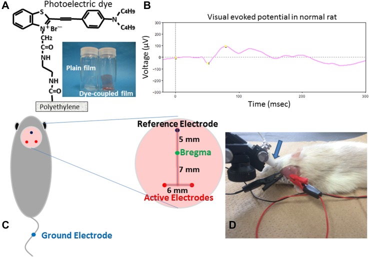
Thin films were made from polyethylene powder and exposed to fuming nitric acid to introduce carboxyl moieties on the film surface. Photoelectric dye molecules, 2-[2-[4-(dibutylamino)phenyl]ethenyl]-3-carboxymethylbenzothiazolium bromide (NK-5962, Hayashibara, Inc., Okayama, Japan), were coupled to carboxyl moieties of the polyethylene film surface via ethylenediamine (Fig. 1a), as described previously [4, 6, 13]. The fuming nitric acid-treated only polyethylene film and the photoelectric dye-coupled polyethylene film were designated as the plain film and the dye-coupled film (Fig. 1a), respectively.
Fig. 1.
Plain polyethylene film and photoelectric dye-coupled polyethylene film, with molecular structure of the dye (a). Visual evoked potential (b) in normal Wistar rat at 6 weeks of the age by photic stimuli (0.5 Hz, 64 summation) of 1000 cd/m2, 10 μs = 0.01 cds/m2 in the background of 0 cd/m2 after overnight dark adaptation. Cranial electrodes (c) on rat’s head to record visual evoked potential. Light stimulation by contact lens light-emitting diode (LED) and visual evoked potential recording (d)
Animals
This study was approved by the Animal Care and Use Committee in Okayama University, based on the Animal Welfare and Management Act in Japan. The dye-coupled films in the size of 1 × 5 mm were implanted subretinally, as described previously [8, 13, 14], in both eyes of 10 male RCS rats at 6 weeks of the age, and the plain films were implanted in both eyes of 10 male RCS rats. In addition, two normal male Wistar rats and two male RCS rats without any surgery were used as positive control and negative control, respectively, to prove technical feasibility to record visual evoked potentials.
Subretinal film implantation
The rats were anesthetized with peritoneal injection of ketamine (87 mg/kg body weight, Ketalar for animals 50 mg/mL, Daiichi Sankyo Propharma, Tokyo, Japan) and xylazine (13 mg/kg body weight, Selactar, 2%, Bayer, AG., Leverkusen, Germany). Under a dissecting microscope, the conjunctival incision was made on the temporal side of the eye, and the sclera, together with the choroid, was cut carefully with blade to expose the retina. Saline was applied to the scleral-choroidal puncture to make a bleb retinal detachment. A sheet of either dye-coupled film or plain film in the size of 1 × 5 mm with one edge marked with black ink was inserted with a forceps to the bleb retinal detachment in both eyes of each rat [8, 13, 14]. The scleral incision was left without suture, and antibiotics eye drops were applied to the eyes. The fundus was examined by indirect funduscopy with a 20 diopter lens to confirm the film insertion. Each rat was housed in a standard rat cage in a room with the 12 h-each light and dark cycle at the Animal Center of Okayama University.
Visual evoked potential recording
Cranial electrodes for recording visual evoked potentials were fixed surgically at 8–9 weeks of the age, 2–3 weeks after the subretinal film implantation. After anesthesia, head skin was incised to expose the cranial bone. Three electrodes (M1 × 6, 1 mm in diameter and 6 mm in length, Sunco Industry, Co., Osaka, Japan), for recording visual evoked potentials, were fixed on the scalp bone to reach the surface of cranial dura mater after the bone puncture was made by a screw driver (Fig. 1c). The electrodes were mounted with dental resin (UNIFAST TRAD, GC Corporation, Tokyo, Japan) [16–20].
Rats were placed overnight in a dark room for dark adaptation. Rats were anesthetized and placed on a heating pad, set at 37 °C. After mydriasis with tropicamide and phenylephrine (Mydrin-P ophthalmic solution, Santen Co., Osaka, Japan), a contact lens with white light-emitting diode (LED) was placed on the corneal surface, with no air bubble trapped between the cornea and the contact lens, and an earth clip, serving as a ground electrode, was placed along the tail (Fig. 1d).
Under dark adaptation, visual evoked potentials to standard flash at a rod-response level (0.01 cd × s/m2 with 1,000 cd/m2 × 10 μs, 0.5 Hz), with background light at 0 cd/m2, were recorded. After light adaptation for 10 min, visual evoked potentials to standard flash (3 cd × s/m2 with 1000 cd/m2 × 3 ms, 1 Hz), with background light at 30 cd/m2, were recorded, based on the International Society for Clinical Electrophysiology of Vision (ISCEV) standards (PuREC and LED Visual Stimulator LS-100/200, Mayo Corporation, Aichi, Japan) [18].
The cranial active electrode on the left side was used to record visual evoked potentials, relative to the reference electrode, in response to light stimulus to the right eye and the electrode on the right side was used to record potentials in response to light stimulus to the left eye (Fig. 1d). Visual evoked potentials were obtained by the summation of 64 recordings after the filtration through an analogue filter, 0.3–500 Hz, and then through a digital filter, 1–100 Hz.
For statistical analysis, amplitudes at 157 consecutive time points in the time frame from 0 to 124 ms, and amplitudes at 158 consecutive time points from 125 to 250 ms were put into repeated-measure analysis of variance (ANOVA). The time frame was divided into the early and late phase, because of the limited capacity in the statistical software (StatView version 5.0, SAS Institute, Inc.).
Results
As a preliminary experiment, visual evoked potentials were recorded in two normal Wistar rats (Fig. 1b), and peaks, such as N1, N2, P1, and P2, were identified to confirm technical feasibility in this study. In contrast, no peaks could be assigned on the recordings in two RCS rats without surgery at 10 weeks of the age. Based on this situation, multipoint analyses for potentials at all the time points were adopted in this study. Visual evoked potential recordings in 7 eyes with dye-coupled films and 7 eyes with plain films were used for the multipoint analyses since these eyes were confirmed histologically to have subretinal implantations of films in full length.
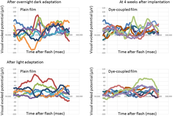
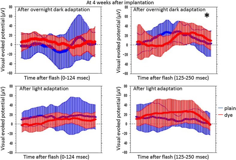
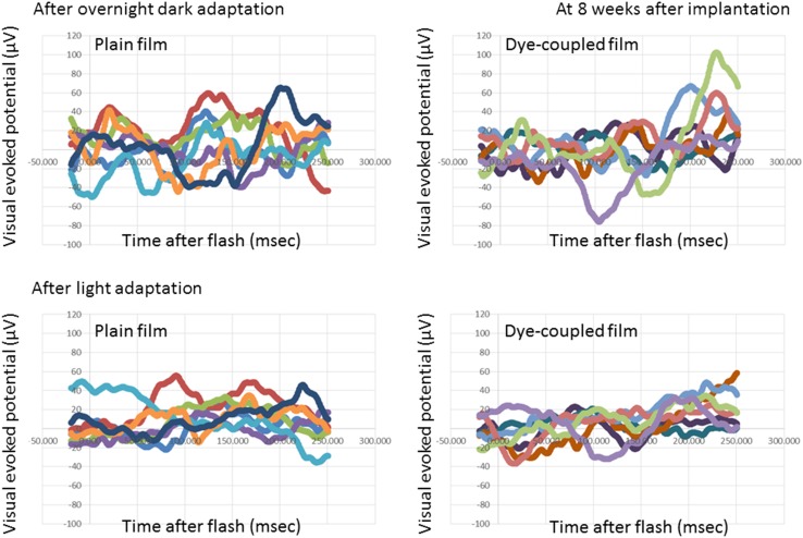
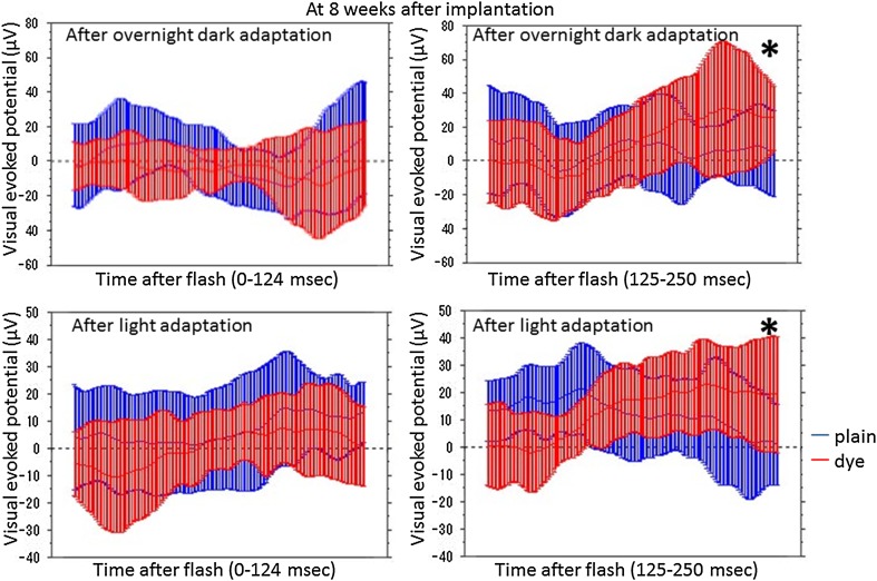
At photic stimulation, following overnight dark adaptation, amplitudes of visual evoked potential in the period of the consecutive time points from 125 to 250 ms after flash were significantly higher in 7 eyes with subretinal dye-coupled film implantation, compared with 7 eyes with plain film implantation, both at 4 weeks and 8 weeks after the surgery (P < 0.0001 and P = 0.0132, respectively, repeated-measure ANOVA, Figs. 2, 3, 4, 5; Table 1). At photic stimulation, following 10 min light adaptation, the amplitudes in the period of the consecutive time points from 125 to 250 ms were significantly higher in 7 eyes with subretinal dye-coupled film implantation, compared with 7 eyes with plain film implantation, only at 8 weeks after the surgery (P < 0.0001, repeated-measure ANOVA, Figs. 2, 3, 4, 5; Table 1).
Fig. 2.
Visual evoked potentials, 4 weeks after subretinal plain film or dye-coupled film implantation in RCS rats’eyes. Two sequential recordings by flashing light stimulation after dark adaptation (top row) and after light adaptation (bottom row) are shown
Fig. 3.
Statistical analyses of visual evoked potentials, 4 weeks after subretinal plain film or dye-coupled film implantation in RCS rats’eyes. Two sequential recordings by light stimulation after dark adaptation (top row) and after light adaptation (bottom row) are shown. Means and standard deviations of potentials in the consecutive time points from 0 to 124 ms and from 125 to 250 ms after flash are shown on the left side and on the right side, respectively. The amplitudes from 125 to 250 ms are significantly larger in flash stimuli to the eyes with dye-coupled films, compared to the eyes with plain films, in dark adaptation (*P < 0.0001), but not in light adaptation (P > 0.9999, repeated-measure ANOVA). The amplitudes from 0 to 124 ms do not show significant difference between the eyes with dye-coupled films and the eyes with plain films
Fig. 4.
Visual evoked potentials, 8 weeks after subretinal plain film or dye-coupled film implantation in RCS rats’ eyes. Two sequential recordings by flashing light stimulation after dark adaptation (top row) and after light adaptation (bottom row) are shown
Fig. 5.
Statistical analyses of visual evoked potentials, 8 weeks after subretinal plain film or dye-coupled film implantation in RCS rats’eyes. Two sequential recordings by light stimulation after dark adaptation (top row) and after light adaptation (bottom row) are shown. Means and standard deviations of potentials in the consecutive time points from 0 to 124 ms and from 125 to 250 ms after flash are shown on the left side and on the right side, respectively. The amplitudes from 125 to 250 ms are significantly larger in flash stimuli to the eyes with dye-coupled films, compared to the eyes with plain films, in dark adaptation and light adaptation (*P = 0.0132 and *P < 0.0001, respectively, repeated-measure ANOVA). The amplitudes from 0 to 124 ms do not show significant difference between the eyes with dye-coupled films and the eyes with plain films
Table 1.
Visual evoked potential in RCS rats’ eyes with dye-coupled film versus plain film implantation
| Visual evoked potential | Time after implantation (weeks) | Two-factor repeated-measure analysis of variance (ANOVA) P value | |||
|---|---|---|---|---|---|
| Condition | Before flash | After flash | |||
| − 20 to 0 ms | 0–124 ms | 125–250 ms | |||
| n = 7 for each class | Time point = 25 | Time point = 157 | Time point = 158 | ||
| After overnight dark adaptation | 4 | Time course | >0.9999 | 0.9810 | <0.0001 |
| 1000 cd/m2, 10 μs = 0.01 cds/m2 | Classa | 0.0472 | 0.6297 | <0.0001 | |
| Background 0 cd/m2 | 8 | Time course | >0.9999 | 0.0092 | <0.0001 |
| 0.5 Hz, 64 summation | Classa | >0.9999 | 0.5398 | 0.0132 | |
| After 10 min light adaptation | 4 | Time course | 0.6431 | 0.0027 | 0.0389 |
| 1000 cd/m2, 3 ms = 3 cds/m2 | Classa | 0.9999 | >0.9999 | >0.9999 | |
| Background 30 cd/m2 | 8 | Time course | 0.9917 | <0.0001 | <0.0001 |
| 1 Hz, 64 summation | Classa | 0.2039 | >0.9999 | <0.0001 | |
aDye-coupled film implantation versus plain film implantation
In contrast, the amplitudes in the period from 0 to 124 ms after flash showed no significant difference between the eyes with dye-coupled films and the eyes with plain films, either under dark adaptation or under light adaptation (Table 1). The amplitudes before photic stimulation also did not show significant difference between the eyes with dye-coupled films and plain films (Table 1).
Discussion
Visual evoked potential is to record electroencephalographic activity in neurons of the visual cortex located at the posterior lobe of the brain, in response to visual stimuli to the eye. To record the response, the summation of repeated multiple recordings is required to detect the signal over the noise in the background of encephalographic activity. The overwritten summation of multiple recordings in visual evoked potential is in contrast with a single recording in electroretinography, as reported previously [14]. In visual evoked potential, flash light or checkerboard pattern reversal is used as visual stimuli. Binocular summation in visual evoked potential is used to assess the influence of simultaneous binocular stimulation on the visual cortical activity, in comparison with monocular stimulation. At the clinical setting, however, visual evoked potential recording has not been used frequently as a clinical examination since less invasive and more informative magnetic resonance imaging has taken over. Another reason for the less use is large interpersonal variation which is also influenced by subtle changes in the recording condition.
In this study, the summation of 64 repeated recordings in response to flashing light was performed to obtain the visual evoked potential in RCS rats, according to the generally accepted protocol [18]. Repeat flashing light stimuli were given to the unilateral eye of RCS rats. Furthermore, the recording was done in rats under general anesthesia which influenced the amplitude and latency of visual evoked potential itself. In preceding studies [19–21], which reported visual evoked potentials in rats, the amplitude of a peak at a certain time point (latency) after flash was used as an indicator for statistical analysis. Since RCS rats at the age, used in this study, do not show visual evoked potential, it is difficult to use for statistical analysis the amplitude of a peak at the certain latency. We, therefore, analyzed, as repeated measures, all recorded amplitudes at consecutive time points within the time frame of 250 ms after flash. The range of 250 ms was chosen since the visual cortical response takes place in this duration after visual stimulation. This kind of multipoint analyses along the consecutive time points would have advantage over conventional peak analysis since the time point (latency) of peaks would vary from rat to rat.
To examine the reproducibility of visual evoked potential in RCS rats, the recording by flashing light was repeated sequentially twice in a rat under general anesthesia at the same session. The first recording was done after overnight dark adaptation. Since repeat light-flashing in the first recording naturally led to light adaptation, the second recording was done after 10 min light adaptation. Both the first and second recording at the same session of general anesthesia showed the significant elevation of the amplitudes in the latter half of the time points within 250 ms.
Subretinal implantation of dye-coupled films and plain films in small rats’ eyes was technically difficult. Therefore, appropriate subretinal film implantation was checked histologically in all rats after visual evoked potential recording was finished 8 weeks after the implantation. About a half of the eyes with implantation was determined as failure, based on the strict guideline that a film in full length was placed subretinally. This strict guideline was adopted in this study because the film which could be inserted in the rats’ subretinal space was small in size (1 × 5 mm), and thus, the effect of film implantation on visual evoked potentials would be expected to be small in magnitude.
In this study, we demonstrated that the photoelectric dye-coupled polyethylene films, implanted in subretinal space of RCS rats’ eyes, induced visual evoked potential, compared with the plain films. In other words, the dye-coupled films, OUReP™, functioned as a retinal prosthesis. Okayama University-type retinal prosthesis, OUReP™, would provide the following advantages over the Argus II™ Retinal Prosthesis System. First of all, OUReP™ does not require a camera or data processing system, or wiring to the retina. A single sheet of OUReP™ would be implanted into the subretinal space by currently-used standard vitreous surgery, just as to treat retinal detachment [10]. A large size of the thin film, up to 10 mm in diameter, could be implanted in the eye, which would provide a wide visual field. Dye molecules in high density on the polyethylene surface work as both an image (light)-receiver and a neuron-stimulator, leading to high resolution of images. In contrast, the Argus II™ System with 60 electrodes provides low resolution of images.
Concurrently at another institution in the United States, the same photoelectric dye (NK-5962) was coupled to a thin film and proven by patch clamp technique to induce action potential changes in neuronal cells [22]. Furthermore, no toxicity has been found for OUReP™ or for the photoelectric dye in any tests for biological evaluation of medical devices, based on the International Organization for Standardization (ISO) 10,993. Manufacturing and quality control has been established at a clean-room manufacturing facility in Okayama University Incubation Center. A first-in-human clinical trial for OUReP™ at Okayama University Hospital, will be planned in consultation with Pharmaceuticals and Medical Devices Agency (PMDA, counterpart of US FDA), based on the Pharmaceuticals and Medical Devices Act in Japan.
Compliance with ethical standards
Conflict of interest
The authors declare that they have no conflict of interest.
Footnotes
Supported in part by a grant for Health and Labor Sciences Research from the Ministry of Health, Labor and Welfare (MHLW) in the Government of Japan.
Contributor Information
Toshihiko Matsuo, Phone: +81-86-235-7297, Email: matsuot@cc.okayama-u.ac.jp.
Tetsuya Uchida, Phone: +81-86-251-8103, Email: tuchida@cc.okayama-u.ac.jp.
References
- 1.Loewenstein JI, Montezuma SR, Rizzo JF. Outer retinal degeneration: an electronic retinal prosthesis as a treatment strategy. Arch Ophthalmol. 2004;122:587–596. doi: 10.1001/archopht.122.4.587. [DOI] [PubMed] [Google Scholar]
- 2.Humayun MS, Dorn JD, da Cruz L, Dagnelie G, Sahel JA, Stanga PE, Cideciyan AV, Duncan JL, Eliott D, Filley E, Ho AC, Santos A, Safran AB, Arditi A, Del Priore LV, Greenberg RJ, Argus II Study Group Interim results from the international trial of Second Sight’s visual prosthesis. Ophthalmology. 2012;119:779–788. doi: 10.1016/j.ophtha.2011.09.028. [DOI] [PMC free article] [PubMed] [Google Scholar]
- 3.Matsuo T. A simple method for screening photoelectric dyes towards their use for retinal prostheses. Acta Med Okayama. 2003;57:257–260. doi: 10.18926/AMO/32824. [DOI] [PubMed] [Google Scholar]
- 4.Uchida T, Ishimaru S, Shimamura K, Uji A, Matsuo T, Ohtsuki H. Immobilization of photoelectric dye on the polyethylene film surface. Mem Fac Eng Okayama Univ. 2005;39:16–20. [Google Scholar]
- 5.Matsuo T, Dan-oh Y, Suga S (Inventors). Agent for inducing receptor potential. Assignee: Okayama University. United States Patent. Patent No.: US 7,101,533 B2. Date of Patent: Sep. 5, 2006.
- 6.Uji A, Matsuo T, Ishimaru S, Kajiura A, Shimamura K, Ohtsuki H, Dan-oh Y, Suga S. Photoelectric dye-coupled polyethylene film as a prototype of retinal prostheses. Aritif Organs. 2005;29:53–57. doi: 10.1111/j.1525-1594.2004.29010.x. [DOI] [PubMed] [Google Scholar]
- 7.Uji A, Matsuo T, Uchida T, Shimamura K, Ohtsuki H. Intracellular calcium response and adhesiveness of chick embryonic retinal neurons to photoelectric dye-coupled polyethylene films as prototypes of retinal prostheses. Artif Organs. 2006;30:695–703. doi: 10.1111/j.1525-1594.2006.00286.x. [DOI] [PubMed] [Google Scholar]
- 8.Tamaki T, Matsuo T, Hosoya O, Tsutsui KM, Uchida T, Okamoto K, Uji A, Ohtsuki H. Glial reaction to photoelectric dye-based retinal prostheses implanted in the subretinal space of rats. J Artif Organs. 2008;11:38–44. doi: 10.1007/s10047-007-0398-8. [DOI] [PubMed] [Google Scholar]
- 9.Okamoto K, Matsuo T, Tamaki T, Uji A, Ohtsuki H. Short-term biological safety of a photoelectric dye used as a component of retinal prostheses. J Artif Organs. 2008;11:45–51. doi: 10.1007/s10047-008-0403-x. [DOI] [PubMed] [Google Scholar]
- 10.Matsuo T, Uchida T, Takarabe K. Safety, efficacy, and quality control of a photoelectric dye-based retinal prosthesis (Okayama University-type retinal prosthesis) as a medical device. J Artif Organs. 2009;12:213–225. doi: 10.1007/s10047-009-0471-6. [DOI] [PubMed] [Google Scholar]
- 11.Matsuo T, Morimoto N. Visual acuity and perimacular retinal layers detected by optical coherence tomography in patients with retinitis pigmentosa. Br J Ophthalmol. 2007;91:888–890. doi: 10.1136/bjo.2007.114538. [DOI] [PMC free article] [PubMed] [Google Scholar]
- 12.Tamaki M, Matsuo T. Optical coherence tomographic parameters as objective signs for visual acuity in patients with retinitis pigmentosa, future candidates for retinal prostheses. J Artif Organs 2011;14:140–150. Erratum. 2011;14:385. doi: 10.1007/s10047-011-0557-9. [DOI] [PubMed] [Google Scholar]
- 13.Alamusi Matsuo T, Hosoya O, Tsutsui KM, Uchida T. Behavior tests and immunohistochemical retinal response analyses in RCS rats with subretinal implantation of Okayama-University-type retinal prosthesis. J Artif Organs. 2013;16:343–351. doi: 10.1007/s10047-013-0697-1. [DOI] [PubMed] [Google Scholar]
- 14.Alamusi, Matsuo T, Hosoya O, Tsutsui KM, Uchida T. Vision maintenance and retinal apoptosis reduction in RCS rats with Okayama University-type retinal prosthesis (OUReP™) implantation. J Artif Organs. 2015;18:264–271. doi: 10.1007/s10047-015-0825-1. [DOI] [PubMed] [Google Scholar]
- 15.Dowling JE, Sidman RL. Inherited retinal dystrophy in the rat. J Cell Biol. 1962;14:73–109. doi: 10.1083/jcb.14.1.73. [DOI] [PMC free article] [PubMed] [Google Scholar]
- 16.Papathanasiou ES, Peachey NS, Goto Y, Neafsey EJ, Castro AJ, Kartje GL. Visual cortical plasticity following unilateral sensorimotor cortical lesions in the neonatal rat. Exp Neurol. 2006;199:122–129. doi: 10.1016/j.expneurol.2006.02.115. [DOI] [PubMed] [Google Scholar]
- 17.You Y, Klistorner A, Thie J, Graham SL. Improving reproducibility of VEP recording in rats: electrodes, stimulus source and peak analysis. Doc Ophthalmol. 2011;123:109–119. doi: 10.1007/s10633-011-9288-8. [DOI] [PubMed] [Google Scholar]
- 18.Odom JV, Bach M, Brigell M, Holder GE, McCulloch DL, Tormene AP, Vaegan. ISCEV standard for clinical visual evoked potentials (2009 update). Doc Ophthalmol 2010;120:111–119. [DOI] [PubMed]
- 19.Woch G, Aramant RB, Seiler MJ, Sagdullaev BT, McCall MA. Retinal transplants restore visually evoked responses in rats with photoreceptor degeneration. Invest Ophthalmol Vis Sci. 2001;42:1669–1676. [PubMed] [Google Scholar]
- 20.Kanda H, Morimoto T, Fujikado T, Tano Y, Fukuda Y, Sawai H. Electrophysiological studies of the feasibility of suprachoroidal-transretinal stimulation for artificial vision in normal and RCS rats. Invest Ophthalmol Vis Sci. 2004;45:560–566. doi: 10.1167/iovs.02-1268. [DOI] [PubMed] [Google Scholar]
- 21.Tomita H, Sugano E, Yawo H, Ishizuka T, Isago H, Narikawa S, Kugler S, Tamai M. Restoration of visual response in aged dystrophic RCS rats using AAV-mediated channelopsin-2 gene transfer. Invest Ophthalmol Vis Sci. 2007;48:3821–3826. doi: 10.1167/iovs.06-1501. [DOI] [PubMed] [Google Scholar]
- 22.Huang F, Bladon J, Lagoy RC, Shorrock PN, Jr, Hronik-Tupaj M, Zoto CA, Connors RE, McGimpsey WG, Molnar P, Lambert S, Rittenhouse AR, Lambert CR. A photosensitive surface capable of inducing electrophysiological changes in NG108-15 neurons. Acta Biomater. 2015;12:42–50. doi: 10.1016/j.actbio.2014.10.023. [DOI] [PubMed] [Google Scholar]


