Abstract
The Dynamic Impact Testing and Calibration Instrument (DITCI) is a simple instrument with a significant data collection and analysis capability that is used for the testing and calibration of biosimulant human tissue artifacts. These artifacts may be used to measure the severity of injuries caused in the case of a robot impact with a human. In this paper we describe the DITCI adjustable impact and flexible foundation mechanism, which allows the selection of a variety of impact force levels and foundation stiffness. The instrument can accommodate arrays of a variety of sensors and impact tools, simulating both real manufacturing tools and the testing requirements of standards setting organizations. A computer data acquisition system may collect a variety of impact motion, force, and torque data, which are used to develop a variety of mathematical model representations of the artifacts. Finally, we describe the fabrication and testing of human abdomen soft tissue artifacts, used to display the magnitude of impact tissue deformation. Impact tests were performed at various maximum impact force and average pressure levels.
Keywords: Robot, Impact testing, Biosimulant human tissue artifacts, Human abdomen soft tissue artifacts
1. Introduction
The movement of manufacturing to countries featuring labor with low hourly wages over the last fifteen years has motivated the development of a new generation of industrial robots that can work side-by-side with human workers (Guizzo and Ackerman, 2012). This has created a new technology of Human-Collaboration-Robotics (HCR), which combines the intelligence and dexterity of humans with the strength, repeatability, and endurance of industrial robots (Pine, 2013, MIT Tech Rev, 2014). Since most robots are powerful moving machines, the safety of workers working around these robots has become a top priority for safety standards development. These safety standards will provide guidance for the development of a comprehensive risk assessment of the robot arm, its tools, its controller, and the whole operating workspace where humans might be present. We are using biosimulant materials for the fabrication of inexpensive, disposable HCR safety testing artifacts. These testing artifacts will make possible the measurement of forces, pressure and strain when humans and robots come into contact and also the magnitude of injuries caused by robot static and impact pressure. In order to test and calibrate these artifacts, we have constructed a Dynamic Impact Testing and Calibration Instrument (DITCI). The subject of this paper is a description of DITCI, its drop loads and sensors, the impact tools, the robot dynamic impact safety artifacts, data analysis, and modeling of test results.
The industrial robot safety standards of the ‘90s significantly increased the protection of plant floor workers, but also restrict access to industrial robots during their normal operation through features such as perimeter fencing, interlocking devices, and safety sensors (e.g., pressure-sensitive mats and light curtains), these features increased the cost of acquisition, installation, and use of industrial robots, increased the complexity of this technology, and decreased industrial production flexibility. These problems triggered the invention of the “Intelligent Assist Device (IAD),” (Colgate et al., 2003). According to RIA (RIA BSR/T15.1, 2003), “IADs are force-based control devices that range from single axis payload balancing to multiple degrees of freedom articulated manipulators.” Officially, IADs are not classified as industrial robots, although some of them consist of articulated industrial robots with modified control modes and force-sensor handles. IADs are commonly used for the manipulation of heavy objects in confined spaces, such as the insertion and mounting of automobile dashboards and seats in the car chassis. The successful use of IADs created the momentum for the development of the Human-Collaboration-Robots (HCRs). A few companies already market HCR robots (Knight, 2014), and there is positive feedback from small or medium-sized companies for whom traditional industrial robots, with all of the required safeguards, would be too expensive to purchase, install, and maintain, and too difficult to program and switch quickly from one task to another. The Robotic Industries Association (RIA), the International Organization for Standardization Technical Committee (ISO/TC) 184, for Industrial Automation Systems and Integration, Sub-Committee (SC) 2, Robots and robotic devices standards writing organizations took notice of the HCR momentum (Fryman and Matthias, 2012) and have included small safe operation HCRs sections in the latest versions of their standards. ISO/Technical Specification (ISO/TS 15066), currently under preparation, will focus exclusively on the safety requirements of collaborative industrial robots. Several collaborative operations have been proposed, which require the implementation of complex safety methods that must undergo thorough testing to minimize the possibility of the use of defective hardware and control software. Various research groups have used human subjects to collect data on pain induced by the clamping force, pressure, and maximum impact force of the HCRs (Haddadin et al., 2008a, Haddadin et al., 2008b, DLR Video, Povse et al., 2010, Muttray et al., 2015). Although the results of these tests are hard to reproduce and can vary even among subjects of similar characteristics, they can be very useful for the preparation of ISO/TS 15066. Unfortunately, human safety testing is not an option for HCR industrial applications every time there is a change of a tool or control program, so the use of biosimulant artifacts is expected to be a good alternative. HCR work cells are relatively easy to relocate, modify and program and this simple changeover capability makes them economically attractive particularly to small manufacturing companies. Since this flexibility can hide safety risks a simple and inexpensive plant floor biosimulant artifacts safety testing technique could make a significant contribution to the success of the HCR technology.
2. The modified “Kapuskasing” static or dynamic impact force testing machine
We have initiated an effort to develop mathematical models and Finite Element Model (FEM) simulations of the physics of the interaction of robot tools with human body parts. For a certain tool geometry and body part properties this study would require information like the contact force, and in addition for dynamic impact the tool acceleration, velocity and displacement. Since we do not use human or animal subjects or cadavers to generate these data, we decided to use biosimulant human tissue artifacts and a simple force applying testing instrument. For testing flexibility this instrument should be capable of applying static or dynamic contact forces.
The Kapuskasing Style Drop Impact Tester1 (Schap Co) is a relatively inexpensive, simply designed, and manually operated desktop static or impact force test machine used by General Motors (GM) and its contractors to measure the quality of leather products used in the GM automobiles. Its simple design allows for easy modifications, the mounting of a variety of sensors, and testing of skin-covered biosimulant samples. The Drop Impact Tester consists of a horizontal metal base plate, the impact load mechanism supporting vertical beam (approximately 410 mm length) mounted on the base plate, a rod bracket dual bushing mechanism mounted on the vertical beam, an indenter rod, and our spring supported stage for mounting the test artifacts. During testing, the test specimen is placed on the stage, the indenter rod is inserted in the two bushings, manually raised to the desired level and released. A rod stop ring is used to set the desired impact head drop height, which together with the rod weight determines the impact energy transferred to the test specimen.
To meet the needs of the DITCI, we made significant modifications to the indenter rod and specimen mount, and, for safety reasons, we built a rectangular plastic plate box enclosure around the Drop Impact Tester (see Fig. 1). The tester metal base plate was bolted on the base plate of the safety box and a system of two pulleys and a rope was used to raise the indenter rod from the outside of the safety box. The front side plate of the box could rotate about two hinges and acted as an access door with a safety locking bolt.
Figure 1.
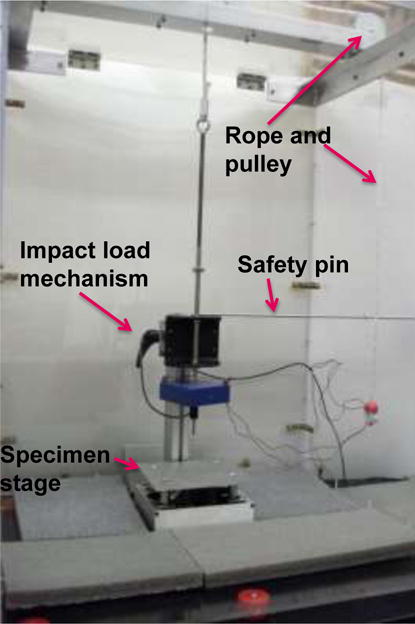
NIST-DITCI for the disposable robot safety artifacts.
For the testing of the skin and soft tissue biosimulant artifact, we fabricated a spring supported stage for mounting the test artifacts in the DITCI (see Fig. 2). The rectangular frame of this stage encloses several steel music wire compression coil springs all of the same 88.9 mm length (3.5″). Because the height of the frame is 50.8 mm (2″), which is lower than the height of the springs, the top plate remains suspended above the frame resting on the top of the springs at a distance equal to 38.1 mm (1.5″), which is the difference of the two heights. The spring-supported stage is used to simulate the stiffness of the abdominal area for a biosimulant artifact. Varying the number and stiffness of the coil springs allows the simulation of different values of body part stiffness. Fig. 3 shows the results of the measurement of the stiffness of the DITCI spring supported stage with calibrated standard static weights. The stiffness produced by six to four commercial steel music wire springs varied from 10.7 N/mm to 7.0 N/mm.
Figure 2.
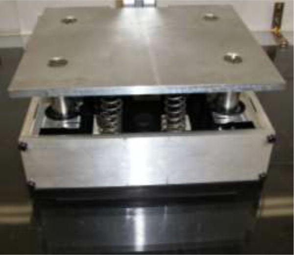
Spring supported stage for mounting the test artifacts in the Dynamic Impact Testing and Calibration Instrument (DITCI)
Figure 3.
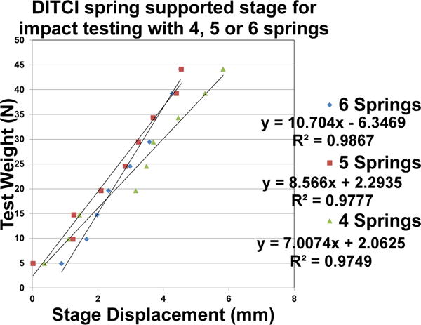
DITCI spring supported stage stiffness test results
3. The drop weights and sensors
The maximum impact force that can exceed recommended biomechanical limits for a certain robot tool varies for the various parts of the human body. This necessitates that DITCI is capable of generating various levels of impact forces. Since the impact force depends on the magnitude of the drop weight and drop height, a simple way to vary the impact force is to have several weights and drop heights available. We fabricated five steel rectangular block weights and several lightweight aluminum plates, for finer control of the total amount of drop weight. Fig. 4 shows three steel weights (blue color) and an aluminum plate. All of these weights were fabricated with a centerline-threaded through hole for mounting. The original Kapuskasing tester indenter rod was replaced with a stainless steel rod threaded at both ends (see Fig. 1). The lower end was used to mount the main drop weight, which carries several sensors, and the upper end was used to mount additional impact force control weights.
Figure 4.
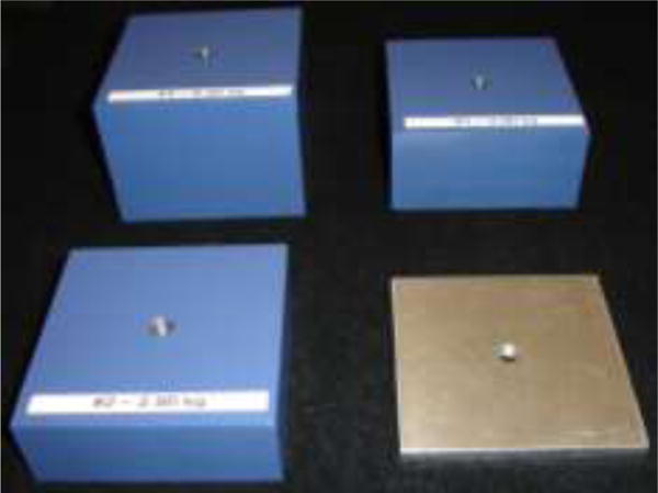
Three steel drop weights (blue color) and an aluminum plate drop weight
For extra impact force control adjustability, several holes were drilled in the indenter rod for the adjustment of the drop height. Figure 5 shows the lower portion of the rod with the safety pin inserted on the seventh hole. The higher number hole corresponds to a lower drop height and a lower impact force.
Figure 5.
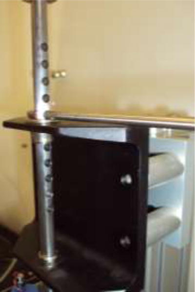
The lower portion of the indenter rod with the safety pin and several pin insertion holes
The first drop weight mounted on the lowest end of the indenter rod was the carrier of two types of sensors used to monitor critical parameters of the impact test. These were pairs of accelerometers and a compressive force measurement load-cell (see Fig. 6). The accelerometer pairs were mounted symmetrically with respect to the vertical centerline of this rectangular drop weight, which was also the mounting direction of the indenter rod. This weight has a square cross section with a 100 mm side length, so its diagonals are normal to each other and form an orthogonal coordinate frame with the centerline of the indenter rod. During the fabrication of this weight, accelerometer mounting holes were drilled and tapped on its top and vertical sides (see Fig. 7). This allowed mounting up to three pairs of accelerometers with their axes lying on three orthogonal planes. The first two of these planes are vertical, passing through the two diagonals of the weight top surface, and the third plane is horizontal, passing through the middle of the rectangular weight block.
Figure 6.
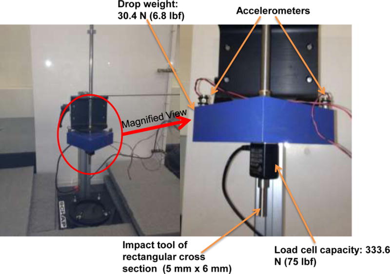
The first drop weight carries two accelerometers and one compressive force measurement load-cell
Figure 7.
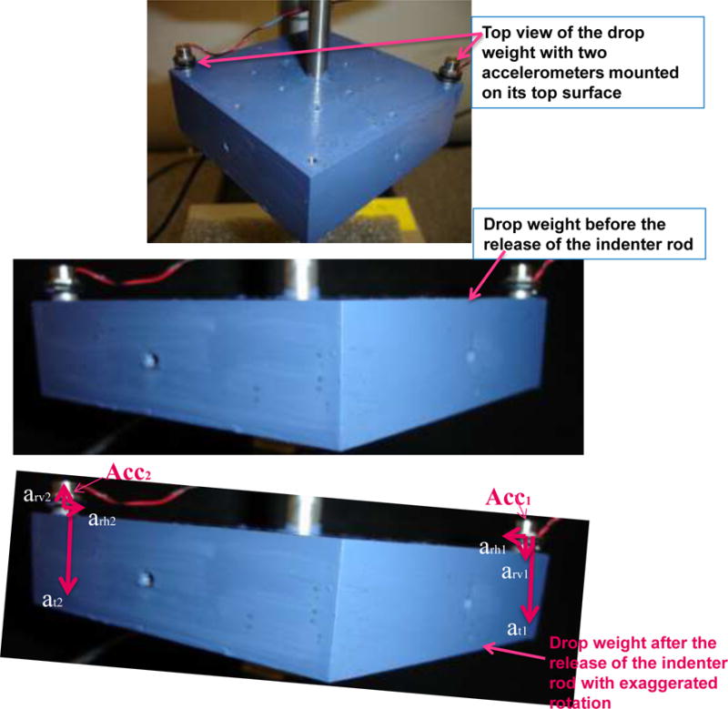
During a drop test two single axis accelerometers, Acc1 and Acc2, measure the acceleration due to translation and rotation (exaggerated in this image)
During a drop test, two single axis accelerometers, Acc1 and Acc2 (see Fig. 7), located on the diagonal of the rectangular weight square top surface, measure its acceleration at due to vertical translation about the indenter rod center line, and the vertical components arv of the angular acceleration around the axis around which the two accelerometers rotate in the event of a loose bushing mounting of the indenter rod of the drop test mechanism. Adding the magnitudes of all the vertical components of the acceleration vectors shown in Fig. 7 gives.
| (1) |
Where acc is the accelerometer output and arv the vertical components of the acceleration due to rotation.
Subtracting the magnitudes of all the vertical components of the acceleration vectors shown in Fig. 7 gives.
| (2) |
Assuming that the locations of the mounting holes of the two accelerometers are symmetrical with respect to the centerline of the indenter rod and any rotation angles of the weight are small, the magnitudes of the above mentioned components of the measured acceleration satisfy the following relations.
| (3) |
This gives the following relations.
| (4) |
| (5) |
Equation (4) indicates that the sum of the two accelerometers’ output divided by two is the drop weight acceleration due to translation, and Eq. (5) indicates that the difference divided by two is the vertical component of the acceleration due to rotation. Performance test results indicate that the angle of rotation of the drop weight is less than 3° about all three axes and that arv is very small compared to at, so it will be ignored in the test results reported in this paper.
4. The impact tools
The compressive force measurement load-cell was mounted on the lower surface of the first drop weight (see Fig. 6) and served as an interface to a variety of impact test tools that we have fabricated with some shown in Fig. 8. The design and dimensions of these tools were taken from various collaborative robot safety studies publications, as well as commonly used plant floor tools. For example, the tools shown in the top left photo of Fig. 8 are recommended designs by the German Institute for Occupational Safety and Health (IFA) in (BG/BGIA, 2011), and have been selected to represent a circular cross section (marked DC of 21.4 mm diameter), a ring cross section (marked IDR25 of 12.9 mm internal diameter, 25 mm outer diameter), a square cross section (marked LS of 19 mm), and a rectangular cross section (marked SR25 of 14.4 mm by 25 mm). The design of the tools shown in the top right photo of Fig. 8 are based on a recommended 30 mm2 cross sectional area requirement of the ISO/TS 15066 (BG/BGIA, 2011), which was deleted after October 2012. The remaining tools shown in the second row in Fig. 8 consist of the tips of commonly used plant floor manufacturing tools attached to a load cell mounting rod. Their dimensions are given in Table 1, in the sequence shown in Fig.8, from left to right. The radius of curvature of the tool tip edges is estimated to be 0.3 mm.
Figure 8.
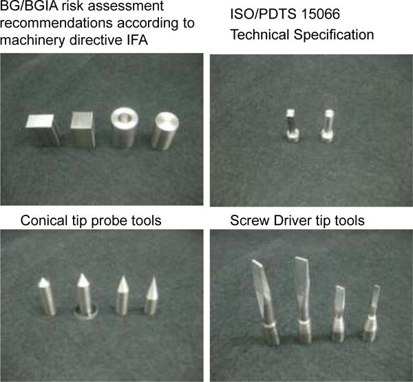
Impact heads of various DITCI test tools
Table 1.
Dimensions of impact heads of conical probes and flat head screw drive tools.
| Conical tip probe tools angle | 90 deg | 60 deg | 45 deg | 30 deg |
|---|---|---|---|---|
| Flat head screwdrivers dimensions (mm) | 8.5×1.5 | 7×1 | 6×1 | 3×0.6 |
Preliminary test results indicate that the damage of our artifacts initiates at the points of impact stress concentrations. For that reason we performed most of our impact tests with tools suspected of having high stress concentration surface characteristics, in order to better understand this damage phenomenon. Future work will attempt to measure the stress concentration factor of generic geometric surfaces, which could be used as a permissible average pressure correction factor. As it was previously mentioned the level of impact damage depends not only on the maximum tool impact force Fmax, but also on the shape and area of the tool surface that comes in contact with the human tissue. For example, a rectangular cross section tool with dimensions of 19 mm × 24 mm generates an average pressure of 35.0 N/cm2 (50.8 psi), for a maximum impact force of 160 N (35.9 lbf). A rectangular cross section tool with dimensions of 5 mm × 6 mm generates an average pressure of 533.3 N/cm2 (773.5 psi), for a maximum impact force of 160 N (35.9 lbf). To bring the pressure down to 35 N/cm2 (50.7 psi), this tool maximum impact force must be reduced to 10.5 N (2.3 lbf). This is important impact test tool geometry because it resembles a hex key, commonly used for most plant floor assembly work. A screwdriver cross section tool with dimensions of 1 mm × 6 mm generates an average pressure of 2 666.6 N/cm2 (3 867.7 psi), for a maximum impact force of 160 N (35.9 lbf). To bring the pressure down to 35 N/cm2 (50.7 psi), the screwdriver cross section tool maximum impact force must be reduced to 2.1 N (0.4 lbf). The maximum impact force level can be controlled through proper robot controller programming or embedded tool features, like a collapsible tool coupling. DITCI impact tests revealed that the soft tissue injury initiates at the points of stress concentration, like tool corners and edges, so most of our current tests are conducted with tools which have these kinds of features, in order to better understand this important phenomenon. FEM simulations support this observation, and the results of the effect of tool tip curvatures will be reported in a future paper.
5. The Biosimulant Artifacts
The use of biosimulant artifacts for characterizing contact situations is not new in general. For the context of Human-Robot Collaboration, however, there is only one body of prior work (Povse et al., 2010) in which an “artificial” human arm has been created for the purpose of representing a body region.
Our current artifacts are more simple and of general use. They consist of disks of biosimulant skin and soft tissue (see Fig. 9). In nature, human skin consists of a thin outer layer called the epidermis, a thick inner layer called the dermis, and subcutaneous fat. The skin is the first layer of defense against impact injuries, which have been studied by medical professionals and forensic researchers. Because cadavers are expensive and difficult to maintain, forensic researchers have been searching for biosimulant materials with mechanical properties similar to those of human skin (Jussila et al., 2005, Ankersen et al., 1999, Gilchrist et al., 2008). Jorma Jussila et.al, report in (Jussila et al., 2005) on a research study to find skin-biosimulant materials with a threshold penetration velocity to metal spheres of a certain size and having tensile strength and elongation at breaking comparable to human skin. The results of this study showed that semi-finished chrome tanned upholstery “crust” cowhide leather of 0.9 mm to 1.1 mm nominal thickness comes very close to matching the average values of the above-mentioned mechanical properties of human skin. There are a few suppliers of this type of material. For all of our artifact test samples, we used chromed tanned cowhide “Full Cowhide Side, Upholstery or Garment Leather Black”, thickness about 1.1mm (Brettuns Village Leather Co).
Figure 9.
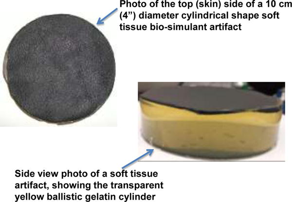
Soft tissue biosimulant artifacts
Water solutions containing 10 % to 30 % mass of gelatin have been studied extensively and are considered to be good human muscle tissue biosimulants (Harvey et al., 1962, Lewis et al., 1982, Bir, 2000, Ankersen et al., 1999, Viano and King, 2008, Koene and Papy, 2011). Experimental work on the use of gelatin as a human muscle tissue biosimulant started in the 1940s (Harvey et al., 1962, Lewis et al., 1982), and, due to the importance of this subject, a large volume of publications has been produced. Here are the most important conclusions relevant to our work. For non-penetrating injuries, a water solution containing 20 % mass of gelatin gives a good representation of muscle tissue impact response (Bir, 2000). For penetrating injuries, a water solution containing 10 % mass of gelatin is more appropriate (Viano and King, 2008). Distilled water should be used for the gelatin solutions to avoid contaminants and acidity variations (Jussila, 2004). Gelatin powder may be stored in a dark, dry environment for a long time without degradation of properties (Jussila, 2004). For all of our test artifact preparations, we used a distilled water solution containing 10 % mass gelatin powder supplied by Vyse Professional Grade Ballistic & Ordnance Gelatin (Gelatin Innovations Co). The solution was poured on top of the skin-biosimulant in an aluminum or glass mold. The glass mold produced artifacts of excellent transparency (yellow ballistic gelatin cylinder, see Fig. 9), and were preferred over the metal molds. The gelatin formed a strong bond with the backside of the skin biosimulant and was never observed to delaminate during impact tests. More recent artifacts contain inexpensive disposable threshold pressure and deformation measurement micro-sensors. These micro-sensors will be used to warn when damage level pressure, at a certain artifact location, has been reached. Future publications will provide more details on this subject.
Samples of commercially available ballistic gelatin have been purchased and kept at ambient temperature in our lab for approximately 18 months with no visible degradation. We have now initiated a longevity study of our biosimulant skin-gelatin artifacts for various packaging designs. Our current intention is that these will be one time use artifacts and tests will be conducted under identical impact conditions for various age artifacts to test the reproducibility of the test results. Future publications will provide more details on this subject. A study has also been initiated on the design and fabrication of biosimulant bone, which is more challenging to simulate than skin and soft tissue. The difficulty of simulating bone for different parts of the human body was the reason of choosing to initiate our studies with abdomen artifacts. Future artifact designs will include skin-soft tissue and bone biosimulants of the proper dimensions and shape for other vulnerable parts of the human body.
6. Data collection modeling and analysis
Acceleration and force data were collected from the sensors described in Section 3. The signals from these sensors were amplified and low-pass filtered before connecting to a LabVIEW DAQmx acquisition board, and a LabVIEW application was written for data collection and analysis. Figure 10 demonstrates the data collection and analysis process flow. Within the LabVIEW application, we streamed raw signal data to the Personal Computer (PC) at a sampling rate of 10 kHz. The signals were saved with sensor and test-run specific metadata (i.e., sensor calibration data, drop height, and sample dimensions), which were later recalled by the program during data analysis. In addition to the signal data, we recorded high-speed video of the impact event to capture visually recognizable phenomena such as shockwave propagation.
Figure 10.
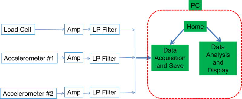
Data collection and analysis block diagram
In order to characterize the biosimulant artifacts, a physical model was required that related material parameters to the observed impact response. We developed initial models for our artifacts assuming an ideal viscoelastic behavior of the skin and soft tissue biosimulants. The viscoelasticity of gelatin has been described in literature (Christensen et al., 1977). Collagen fibers have also been described using a viscoelastic model (Gilsenan and Ross-Murphy, 2000). The basic viscoelastic constitutive model is
| (6) |
where F is applied force, x is displacement, m is mass, η is the viscoelastic coefficient, and k is the spring constant. Here, we also see velocity and acceleration as the first and second derivatives of displacement with respect to time. By integrating our acceleration signal, we obtained velocity and displacement data. These, combined with the force signal, were used to fit the three material parameters, m, η and k.
Fitting was performed using the LabVIEW application. After raw signals were streamed to the PC, the LabVIEW application loaded the signals for analysis. Raw signals were scaled and processed to reduce noise. The acceleration signals were merged (as discussed in Section 3), and then integrated to obtain velocity and displacement data. The application then performed linear least squares fitting and returned the three material parameters.
7. Test results
The DITCI instrument was successfully calibrated to yield a maximum impact force of 160 N (35.9 lbf), by setting the drop height and mass accordingly, by using a rectangular cross-section impact tool with dimensions 19 mm × 24 mm (resulting in an average pressure of 35 N/cm2). Typical force, acceleration, velocity, and displacement responses were shown previously in Fig. 11. The initial drop of the impact tool consists of two segments, a free fall, and then the contact with the artifact. While the force is zero the tool is in free fall and actually reaches an acceleration of 9.8 m/s2 as can be clearly seen from the acceleration graph (second Fig.11 graph). As the tool comes closer to the artifact the trapped air between the two surfaces slows down the dropping tool, which can also be seen from the slight decrease of the acceleration. At approximately 1.8 seconds the force becomes negative indicating that impact has occurred. At that moment the tool has dropped by approximately 0.045 m. As long as the force is negative the tool is in contact with the artifact and according to the fourth graph its maximum drop height is approximately 0.071 m. Subtracting the tool contact drop height from the maximum drop height gives 0.026 m, which represents the artifact deformation and its downward movement due to the impact.
Figure 11.

Display of the analysis of DITCI data for approximately 160
Our high speed video camera shows that depending on the DITCI test conditions the impact tool might bounce on the artifact surface after the first contact, and then the tool and artifact move against each other and impact again in a few millisecond time at a higher impact force. That can be clearly seen in Fig. 11 top graph of Force (N) versus time. The phrase “maximum impact force Fmax” is in this case making reference to the second impact force, which causes the maximum damage to the artifact. At this force impact level, though we observed no permanent injury to the biosimulant skin or soft tissue layers. In contrast, by using impact tools with smaller cross-sections, such as a 1 mm × 6 mm flathead screwdriver tool, impact resulted in permanent skin injury, even at 160 N (see Fig. 12). We observed that the level of impact injury depends not only on the maximum tool impact force Fmax, but also on the shape and area of the tool surface that comes in contact with the human tissue. This observation then dictates that when retooling an industrial robot, the size and shape of the tool tip must be accounted for in the operating mode, even when operating at the same speed and maximum force. Redesigning the tool tip to minimize stress concentrations during impact, using contact force limiting devices and/or reducing the robot arm’s end plate speed are a few ways to reduce the level of impact damage.
Figure 12.

Skin biosimulant injury from screwdriver tool.
Video footage of impact, shot at 2000 frames per second, revealed that considerable elastic deformation took place throughout the artifacts when hit with small cross-section tools. Figure 13 shows the video frames of the impact tools’ maximum penetration in the biosimulant artifact, for the 19 mm × 24 mm tool (left) and the 1 mm × 6 mm tool (right). For the same Fmax, the second tool penetration was 227 % of the penetration generated by the first tool. The skin biosimulant coupled with the soft tissue oscillated under the impact tool, but the skin was never observed to delaminate from the soft tissue during testing. Shockwave propagation was observed in the bulk gelatin with all impact tools, particularly for impacts closer to the edge of the samples.
Figure 13.
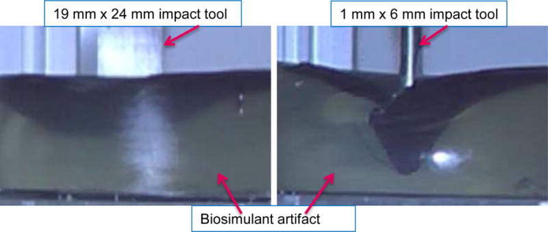
Video frames of the impact tools’ maximum penetration in the biosimulant artifact, for the 19 mm × 24 mm tool (left) and the 1 mm × 6 mm tool (right).
The viscoelastic model of the skin biosimulant was first tested independently of the soft tissue and without the spring supported stage. Initial testing of the skin biosimulant took place with a circular frame over which the skin was stretched, and the impact tool was dropped in the center of the test skin. The impact force was calibrated to be below the point at which the impact tool penetrated the skin. Data from these impact events were collected as described in Section 6, and they were fit to the viscoelastic model using a linear least squares technique. As a first approximation, it was assumed that the spring constant and viscoelastic coefficient were constant. The fitted parameters could also be measured or estimated from our sensor data. The impact mass was directly measurable, the spring constant was estimated using Hooke’s law, and the viscoelastic coefficient was estimated by calculating the rate of exponential decay of the response peaks. The least squares fitting agreed with our measurement and estimation of the mass and viscoelastic constant, but the spring constant could not be fit due to non-linearity. This non-linearity was observed by plotting force as a function of displacement, for 5.5 cm, 7.0 cm, and 8.5 cm drop weight heights, utilizing force and displacement data that was sampled over the same period of time (see Fig. 14). The slope of the curves of Fig. 14 represents the viscoelastic stiffness k of the skin biosimulant. As can be seen from these test results the value of k is low for small penetration depths, but rapidly increases with the penetration depth. The rate of increase is higher for the greater drop height. Since the greater drop height corresponds to greater impact velocity it is obvious that for a certain tool size and geometry k is a nonlinear function of at least the penetration depth and impact velocity. A more advance spring constant model is now investigated and results will be reported in a future publication. The skin biosimulant coupled with the soft tissue is more complex still, and its behavior is currently being investigated through finite element analysis, and relevant literature studies (Larson, et al., 1996) (Salisbury and Cronin, 2009).
Figure 14.

Impact force plotted as a function of displacement for three drop heights.
Our latest attempt at understanding the severity of impact involves the use of passive markers, or embedded materials that display some visual indication of the maximum impact force.
8. Summary and Conclusions
Competition has motivated the development of a new generation of industrial robots that can work side-by-side with human workers, which has motivated the safety testing of these robots, their tools, and operating control modes. A simple drop weight impact-testing machine was modified to simulate an impact between a human and a robot. The drop weight and height can be varied to simulate different levels of impact forces. A spring supported test specimen plate may be used to simulate the stiffness of various part of the human body underneath the skin and surface soft muscle tissue. The drop weight mounted on the lowest end of the indenter rod was instrumented to allow the monitoring of the test impact force, acceleration, velocity, and displacement. A variety of robot impact tools have been fabricated in order to test their impact injury potential. Some of them are specified by occupations safety studies and standards setting organizations, and others resemble tools used for manufacturing operations. Several artifact sizes have been built and tested. These artifacts use biosimulant materials with mechanical properties similar to human skin and soft tissue. Data acquisition and analysis software was developed that recorded the force, acceleration, velocity, and displacement of the impact tool during each test. A linear lumped parameter model representation was developed for the biosimulant skin, which agreed well with the test data with the exception of the spring constant, which turned out to be highly nonlinear. Test results indicate that for a certain tool size and geometry k is a nonlinear function of at least the penetration depth and impact velocity. Preliminary test results appear to justify the importance of the shape and area of the tool surface that comes in contact with the human tissue. Commonly used plant floor manufacturing tools, like hex-keys, screwdrivers, and probes, have the potential to generate significant human tissue penetrations and injuries under certain impact conditions. Studies have been initiated for the development of inexpensive disposable biosimulant bone, and threshold pressure sensors, the modeling of the impact phenomenon, and the reproducibility of artifacts and test results.
Acknowledgments
The authors would like to thank John Stopher for his help with the development of data analysis and modeling software. We would also like to thank Jay Brandenburg, Richard Lake, and Dana Strawbridge, of the NIST Fabrication Technology Division for the fabrication of the various mechanical parts of DITCI. We also want to thank the reviewers of this paper for their constructive comments.
This work was supported by the Robotic Systems for Smart Manufacturing Program of the Intelligent Systems Division, Engineering Laboratory, National Institute of Standards and Technology, USA.
Footnotes
Certain commercial equipment is identified in this paper to adequately describe the experimental procedure. Such identification does not imply recommendation or endorsement by the National Institute of Standards and Technology nor does it imply that the equipment identified is necessarily the best available for the purpose.
References
- Ankersen J, Birkbeck AE, Thomson RD, Vanezis P. Puncture resistance and tensile strength of skin simulants. Proceedings of the Institution of Mechanical Engineers, Part H: Journal of Engineering in Medicine. 1999;213(6):493–501. doi: 10.1243/0954411991535103. [DOI] [PubMed] [Google Scholar]
- BG/BGIA. Deutschen Gesetzlichen Unfallversicherung, BG/BGIA risk assessment recommendations according to machinery directive-Design of workplaces with collaborative robots. Sankt Augustin, Germany: 2011. February 2011, http://publikationen.dguv.de/dguv/pdf/10002/bg_bgia_empf_u_001e.pdf. [Google Scholar]
- Bir CA. PhD thesis. Wayne State University Bioengineering Center; Detroit, Michigan: 2000. The evaluation of blunt ballistic impacts of the thorax. [Google Scholar]
- Brettuns Village Leather; Lewiston, ME: http://www.brettunsvillage.com/leather/sides.htm. [Google Scholar]
- Christensen MS, Hargens CW, III, Nacht S, Gans EH. Viscoelastic properties of intact human skin: instrumentation, hydration effects, and the contribution of the stratum corneum. Journal of Investigative Dermatology. 1977;69(3):282–286. doi: 10.1111/1523-1747.ep12507500. [DOI] [PubMed] [Google Scholar]
- Colgate JE, Peshkin M, Klostermeyer SH. Intelligent Assist Devices in Industrial Applications: A Review. Proceedings of Intelligent Robots and Systems. (IROS) Conference; Las Vegas, Nevada, USA. 2003. pp. 2516–2521. [Google Scholar]
- DLR Video. German Aerospace Center (DLR) Safe Human-Robot Interaction. Video Clip Posted on You Tube. http://www.youtube.com/watch?v=dnUwqngH0bM.
- Fryman J, Matthias B. Safety of Industrial Robots: From Conventional to Collaborative Applications, in proceedings of ROBOTIK 2012. Munich 2012 Jun; [Google Scholar]
- Gelatin Innovations; Schiller Park IL: http://www.gelatininnovations.com/ [Google Scholar]
- Gilchrist MD, Keenan S, Curtis M, Cassidy M, Byrne G, Destrade M. Measuring knife stab penetration into skin simulant using a novel biaxial tension device. Forensic Science International. 2008;177(1):52–65. doi: 10.1016/j.forsciint.2007.10.010. [DOI] [PubMed] [Google Scholar]
- Gilsenan PM, Ross-Murphy SB. Viscoelasticity of thermoreversible gelatin gels from mammalian and piscine collagens. Journal of Rheology. 2000;44(4):871–883. [Google Scholar]
- Guizzo E, Ackerman E. How Rethink Robotics Built Its New Baxter Robot Worker. IEEE Spectrum. 2012 Sep;:18. http://spectrum.ieee.org/robotics/industrial-robots/rethink-robotics-baxter-robot-factory-worker.
- Haddadin S, Albu-Schaffer A, De Luca A, Hirzinger G. 2008 IEEE/RSJ International Conference on Intelligent Robots and Systems. Acropolis Convention Center Nice; France: 2008a. Sep 22–26, Collision Detection and Reaction: A Contribution to Safe Physical Human-Robot Interaction; pp. 3356–3363. [Google Scholar]
- Haddadin S, Albu-Schaffer A, De Luca A, Hirzinger G. Proceeding of IARP International Workshop on Technical challenges and for dependable robots in Human environments. Pasadena, USA: 2008b. May, Evaluation of Collision Detection and Reaction for a Human-Friendly Robot on Biological Tissues; p. 18. [Google Scholar]
- Harvey EN, McMillen JH, Butler EG, et al. Mechanism of wounding. In: Coates JB, editor. Wound Ballistics, Chapter III. US Army Surgeon General; Washington D.C.: 1962. pp. 143–235. http://history.amedd.army.mil/booksdocs/wwii/woundblstcs/chapter3.htm. [Google Scholar]
- ISO 15066. International Organization for Standardization, Robots and Robotic Devices-Industrial Safety Requirements-Collaborative Industrial Robots. ISO TC 184/SC 2 N/PDTS 15066: Under preparation [Google Scholar]
- Jussila J. Preparing ballistic gelatin—review and proposal for a standard method. Forensic Science International. 2004;141:91–98. doi: 10.1016/j.forsciint.2003.11.036. [DOI] [PubMed] [Google Scholar]
- Jussila J, Leppaniemib A, Paronenc M, Kulomaki E. Ballistic skin simulant. Forensic Science International. 2005;150:63–71. doi: 10.1016/j.forsciint.2004.06.039. [DOI] [PubMed] [Google Scholar]
- Koene L, Papy A. Towards a better, science-based, evaluation of kinetic non-lethal weapons. Int J Intelligent Defense Support Systems. 2011;4(2):169–186. [Google Scholar]
- Knight W. Human-Robot Collaboration Gaining an Enormous Amount of Momentum. Robotics Trends, MIT Technology Review. 2014 May 01; [Google Scholar]
- Larson RG, et al. A predictive model for impact response of viscoelastic polymers in drop tests. Rheologica Acta. 1996;35(3):252–264. [Google Scholar]
- Lewis RH, Clark MA, O’Connell KJ. Preparation of gelatine blocks containing tissue samples for use in ballistics research. American Journal of Forensic Medicine and Pathology. 1982;3(2):181–184. doi: 10.1097/00000433-198206000-00015. [DOI] [PubMed] [Google Scholar]
- MIT Technology Review. How Human-Robot Teamwork Will Upend Manufacturing. 2014 Sep 16; [Google Scholar]
- Muttray A, et al. Collaborative robots - Determination of pain sensitivity at the human-machine interface. 2015 in preparation. [Google Scholar]
- Pine A. Just Ahead: The Robotics Revolution. Kiplinger Magazine; 2013. Jan 8, http://www.kiplinger.com/article/spending/T057-C021-S001-just-ahead-the-robotics-revolution.html?&si=1. [Google Scholar]
- Povse B, et al. Industrial Robot and Human Operator Collision. IEEE International Conference on Systems, Man and Cybernetics; Istanbul, Turkey. October.2010. [Google Scholar]
- RIA BSR/T15.1. Draft Standards for Intelligent Assist Devices – Personnel Safety Requirements 2003 [Google Scholar]
- Salisbury CP, Cronin DS. Experimental Mechanics. Vol. 49. Schap Specialty Machine Co.; Spring Lake, Michigan: 2009. Mechanical Properties of Ballistic Gelatin at High Deformation Rates; pp. 829–840. [Google Scholar]
- Viano DC, King AI. Biomechanics of chest and abdomen impact. In: Peterson DR, Bronzino JD, editors. Biomechanics: Principles and Applications. CRC Press; Boca Raton: 2008. Chapter 24. [Google Scholar]


