Abstract
Background
Combining in vitro mouth–throat deposition measurements, cascade impactor data and computational fluid dynamics (CFD) simulations, four different inhalers were compared which are indicated for chronic obstructive pulmonary disease (COPD) treatment.
Methods
The Respimat inhaler, the Breezhaler, the Genuair, and the Ellipta were coupled to the idealized Alberta throat model. The modeled dose to the lung (mDTL) was collected downstream of the Alberta throat model using either a filter or a next generation impactor (NGI). Idealized breathing patterns from COPD patient groups – moderate and very severe COPD – were applied. Theoretical lung deposition patterns were assessed by an individual path model.
Results and conclusion
For the Respimat the mDTL was found to be 59% (SD 5%) for the moderate COPD breathing pattern and 67% (SD 5%) for very severe COPD breathing pattern. The percentages refer to nominal dose (ND) in vitro. This is in the range of 44%–63% in vivo in COPD patients who display large individual variability. Breezhaler showed a mDTL of 43% (SD 2%) for moderate disease simulation and 51% (SD 2%) for very severe simulation. The corresponding results for Genuair are mDTL of 32% (SD 2%) for moderate and 42% (SD 1%) for very severe disease. Ellipta vilanterol particles showed a mDTL of 49% (SD 3%) for moderate and 55% (SD 2%) for very severe disease simulation, and Ellipta fluticasone particles showed a mDTL of 33% (SD 3%) and 41% (SD 2%), respectively for the two breathing patterns. Based on the throat output and average flows of the different inhalers, CFD simulations were performed. Laminar and turbulent steady flow calculations indicated that deposition occurs mainly in the small airways. In summary, Respimat showed the lowest amount of particles depositing in the mouth–throat model and the highest amount reaching all regions of the simulation lung model.
Keywords: throat model, NGI, inhalation, lung deposition, CFD, Respimat
Introduction
The delivery efficiencies of the Respimat inhaler (Spiriva) and three competing inhalers, the Breezhaler (Seebri) the Genuair (Eklira), and the Ellipta (Relvar) inhalers were expected to differ. Except for the Ellipta, the evaluated inhalers contained a muscarinic receptor antagonist as active ingredient.
As a direct comparison of inhalers in real patients is difficult because of the variability inevitably introduced by the patients, the inhalers were compared using in vitro methods and computational simulations considering morphometric features of throat and lung and flow mechanics as described by Finlay.1 The experimental setup for the inhaler tests produced realistic breathing patterns and consisted of the Alberta throat model,2 a lung simulator, and a next generation pharmaceutical impactor (NGI). The setup was chosen in analogy to Olsson et al3 and Wachtel et al.4 The breathing patterns had previously been recorded of chronic obstructive pulmonary disease (COPD) patient groups with different severities and using devices of different flow resistance.5 For this study, moderate and very severe COPD cohorts were selected according to global initiative for chronic obstructive lung disease (GOLD) criteria6 and the flow resistance of the device under test5 was considered.
From real lung casts to idealized computational lung models
The first realistic data and dimensions of the human lung were collected by developing resin casts7 or silicone rubber casts of the lung.8,9 Based on these measurements Finlay et al developed an idealized lung geometry10 whereas other 3D-lung models expanding to the 4th or up to the 15th lung generation consisted of idealized geometries based on CT scan data.11–13 Results of laminar and turbulent simulations with different inlet profiles were compared showing that with turbulent inlet profiles laminar and low Reynolds number (LRN) k–ω simulations provided the best fit to their empirical results.14 A detailed overview over different lung models is provided by Longest and Holbrook.15
In the present single path computational fluid dynamics (CFD) model the particle deposition by impaction was simulated in the different regions of the lung. Comparison with the receptor density provided an idea of favorable deposition sites which could be reached using the right particle sizes at specific flow conditions and inhaler-specific mass-flows. The deposition model did not predict pharmacologic effects in vivo but it characterized the match between possible target and deposition site of the aerosol particles under well-defined conditions.
Muscarinic receptor density
Inhaled anticholinergics, such as tiotropium bromide, glycopyrronium bromide, aclidinium bromide, and umeclidinium bromide are the most effective class of bronchodilators in the treatment of COPD because airway cholinergic tone is the only known reversible component of this disease.16 M1 and M3 receptors are the targets for the therapeutic application of muscarinic antagonists in COPD disease treatment. Antagonism of M3 mediates the bronchodilatation because smooth muscles in the lungs are relaxed and, therefore, the airways are expanded, making breathing easier.17 Blocking of M1 and M3 in the submucosal glands decreases the mucus secretion that can plug the airways.
Due to the importance of M1 and M3 receptors their density was visualized in the 3D-lung model by coloring it according to Bmax values (maximum receptor density, Table S1).18 For the receptor density in the human trachea Bmax values of M1, M2, and M3 receptors were not stated separately, but the density was assumed to be higher than in the bronchi.17,19,20 The total receptor density in the human tracheal smooth muscle membrane was found to be 123 fmol/mg (±16) protein21 but it was not clear in which proportion the M2 and M3 receptors existed in the human trachea.
Materials and methods
Test inhalers
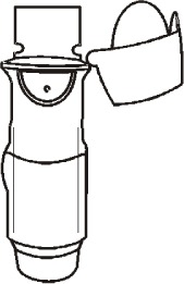
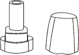
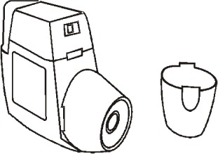
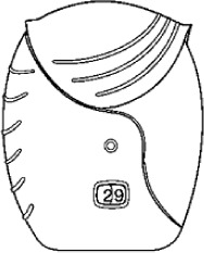
Respimat contained tiotropium in an aqueous solution and was compared to Breezhaler, a capsule based dry powder inhaler, Genuair, and Ellipta, two multidose dry powder inhalers. Table 1 summarizes the outer appearance and the main features of the inhalers used in this study.
Table 1.
Respimat inhaler, Breezhaler, Genuair, and Ellipta
| Respimat | Breezhaler | Genuair | Ellipta | |
|---|---|---|---|---|
| Inhaler (sketches) |
|
|
|
|
| Batches obtained for this study | 204950, 205369 | S0009, S0007 | F4, F3 | R659388, R659402 |
| Active ingredient | Tiotropium | Glycopyrronium | Aclidinium | Fluticasone furoate/vilanterol |
| Daily delivered dose | 5 μg (in 2 puffs) | 44 μg | 2×322 μg | 92/22 μg |
| Nominal dose | 2.5 μg | 50 μg | 322 μg | 92/22 μg |
| Other ingredients | Benzalkonium chloride, EDTA, water, HCl | Lactose monohydrate, magnesium stearate | Lactose monohydrate | Lactose monohydrate, magnesium stearate |
| Indication | COPD, asthma | COPD | COPD | COPD, asthma |
| Common side effects (may affect up to 1 in 10 people) according to patient leaflet | Dry mouth | Dry mouth, difficulty sleeping, runny or stuffy nose, sneezing, sore throat, diarrhea or stomach ache | Headache, sinusitis, nasopharyngitis, cough, diarrhea | Headache, common cold, sore, fungal infection, bronchitis, pain/irritation/infection of nose/throat, flu, itchy, runny or blocked nose, cough, voice disorders, bone weakening, stomach pain, back pain, fever, joint pain |
| Manufacturer | Boehringer Ingelheim | Novartis | Almirall | GlaxoSmithKline |
| Market authorization | 2007 (Spiriva Respimat COPD)41 2014 (Spiriva Respimat, asthma)42 | 201243 | 201344 | 2013 Relvar Ellipta45 2013 Anoro Ellipta46 2014 Incruse Ellipta47 |
| Dosage | 1× daily 2 puffs | 1× daily | 2× daily | 1× daily |
| Handling in daily use (not first initiation, only main handling steps) | Turn the base, open cap, exhale, press the dose release button while taking a slow, deep breath, close cap | Open the inhaler, insert a capsule, pierce the capsule, exhale, inhale rapidly and deeply, repeat if there is still powder in the capsule | First press the green dose release button, exhale, then inhale strongly and deeply, control if the green control window turns red (if it is not, repeat inhalation) | Open the inhaler by sliding down the cover, exhale, inhale, close the inhaler |
Note: Summary of the administration and possible side effects according to patient leaflets.
Abbreviations: COPD, chronic obstructive pulmonary disease; EDTA, ethylenediaminetetraacetic acid.
Flow resistances of the inhalers
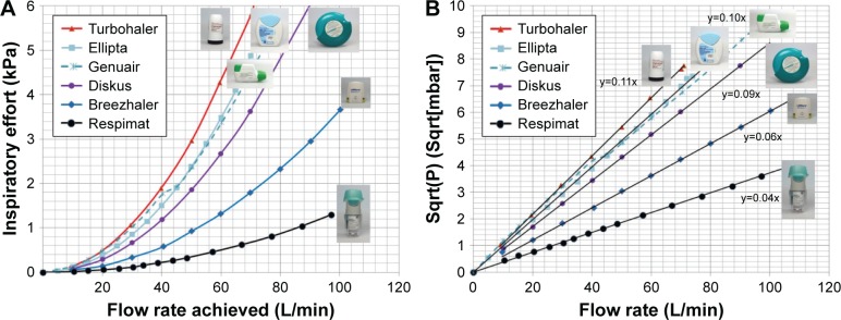
Besides the different operating principles and required handling steps the flow resistances of the devices affect the patient’s inhalation experience. For adjusting the breathing patterns to the three different inhalers their flow resistances were determined. Therefore, the pressure drops were measured at different specified flow rates in a setup according to USP <601.. Two graphical presentations of the inspiratory effort are given in Figure 1 displaying the typical range by including a range of commercially available inhalers. Technically, the pressure drop generated by the inhaler is measured as a function of the flow rate.
Figure 1.
Air flow characteristics of marketed inhalers.
Notes: (A) Flow resistance of the inhalers (n=3 replicates) in the context of other marketed products. Respimat has the lowest resistance of 0.04 Sqrt(mbar) min/L, followed by Breezhaler, 0.06 Sqrt(mbar) min/L; Genuair, 0.1 Sqrt(mbar) min/L; and Ellipta, 0.1 Sqrt(mbar) min/L. P is the pressure at specified flow and Sqrt() is the square root of the contents included in brackets. (B) Linear regressions of the square root of the pressure drop as a function of the flow rate for different inhalers. The indicated slope equals to the flow resistance. Using SI units, for Respimat a resistance of 22,300 Sqrt(Pa) s/m3 was found, for Breezhaler 36,200 Sqrt(Pa) s/m3. Genuair and Ellipta showed the same flow resistance of 58,400 Sqrt(Pa) s/m3. Regression coefficients are provided and rounded to 1.00 with the exception of Genuair, where a moving part inside modifies the flow resistance at about 40 L/min.
In vitro deposition testing setup
The mass median aerodynamic diameter (MMAD), the fine particle fraction (FPF [<5 μm]) of the nominal dose (ND), and the biorelevant modeled dose to the lung (mDTL) were measured using either a NGI (Figure 2) or a filter setup (Figure 3). The setup shown in Figure 2 consisted of a throat model (Alberta throat model made of aluminum, Prof W Finlay, Univ. Alberta), a mixing inlet connected to the lung simulator (ASL 5000 Active Servo Lung, IngMar Medical, Pittsburgh, USA) and connected to the preseparator which was placed on top of the NGI (Copley Scientific Ltd, Nottingham, UK). The inside of the throat model, the preseparator and the impactor cups were coated with Brij®-glycerol emulsion (Brij 35®, Polyoxyethylenmonolaurylester, Serva, Electrophoresis GmbH, Heidelberg, Germany) for avoiding re-entrainment and for simulating the wet mucosal surface. The inhalers under test were attached to the throat model using different appropriate air-tight adapters (manufactured by Boehringer Ingelheim, Germany) for their mouthpieces. They were centered with the mouth cavity and aligned with their axis parallel to the “tongue”.
Figure 2.
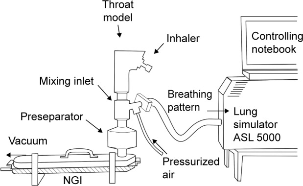
Impactor measurement.
Notes: Setup consisting of Alberta throat model, mixing inlet, lung simulator, and NGI. For aqueous aerosol (Respimat) the feed air was humidified (RH >95%) in order to avoid artificial particle shrinking inside the impactor. For dry powders, ambient nonhumidified air was used, which had a relative humidity of 40%–50%.
Abbreviations: ASL, active servo lung; NGI, next generation impactor; RH, relative humidity.
Figure 3.
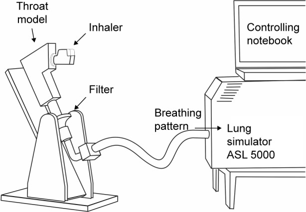
Filter measurement.
Notes: Setup consisting of Alberta throat model, lung simulator and filter for the collection of the modeled dose to the lung. The tilt provided the horizontal operation required for the Genuair inhaler.
Abbreviation: ASL, active servo lung.
Breathing patterns
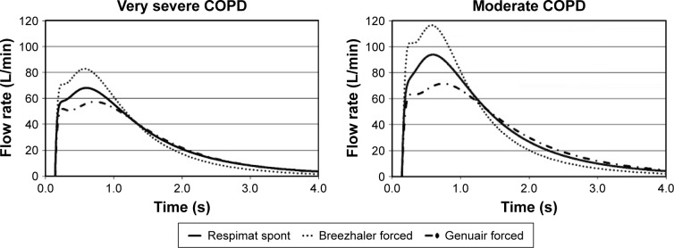
The breathing patterns shown in Figure 4 were generated in the previous study5 from patients with moderate or very severe COPD according to GOLD. Average breathing patterns (flow rate vs time) were found to resemble a curve composed of at least two skewed log-normal distributions. A mathematical model was adapted to fit these curves depending on dedicated inhalation experiments depending on severity of disease and flow resistance of the device. Here, the breathing patterns were used for the in vitro experiments as well as for setting a representative flow during the CFD simulation. For CFD simulation the mean flow rates of very severe COPD patterns during actual drug delivery of 55, 74, and 38 L/min were used for simplification. The peak flow rates would be higher but the mean flow rates were still comparable to the flow rates of the breathing patterns used by Zanker et al22 for in vitro deposition experiments with Seebri Breezhaler. The existence of many publications on different inhalation breathing patterns shows that there is no generally accepted set of flow profiles available yet.
Figure 4.
Inhalation flow profiles.
Notes: The profiles in full (Respimat, spontaneous inspiration), dotted (Breezhaler, forced inspiration), and broken thick lines (Genuair and Ellipta, forced inspiration) were used in this study and represent fit curves to average inhalation profiles of patients with the indicated severity of disease and taking into account the different flow resistances of the devices and the breathing modes. Reproduced with permission from Respiratory Drug Delivery 2006, Virginia Commonwealth University and RDD Online.5
Abbreviation: COPD, chronic obstructive pulmonary disease.
For the lower flow of the very severe COPD-pattern the first setup with NGI (Figure 2) was used. The higher flow rates of the moderate COPD-pattern demanded a simpler filter setup (Figure 3) because a peak flow up to 120 L/min was required. The correct generation of breathing patterns was validated by a MasterScope pneumotachograph (Jaeger/Cardinal Health, Hoechberg, Germany). During the check runs the inhalers were located inside an airtight plastic chamber with their mouthpieces protruding to the outside. All air intruding into the chamber was registered by the pneumotachograph. The breathing pattern was accepted when the maximum air flow and the inhalation volume did not differ >7% from the reference values.
The air flow in the NGI was constantly set to 70 L/min (for Respimat measurements with low flow rate of the breathing pattern) or 100 L/min (for the dry powder inhalers and higher flow rates of the breathing patterns). When the lung simulator started the breathing pattern it actually reduced the incoming pressurized air while the outflow remained constant. In this way, the aspired air was drawn through the throat model.
The three inhalers were used according to the patient information leaflet, for example, the Genuair inhaler was used in a horizontal position, the inhalation with the Breezhaler was repeated, when the emptying of the capsule was not successful at the first try. All experiments were performed in triplicate.
Collection of samples
For all inhalers 10 doses were inhaled by the testing system to reach a concentration of API (active pharmaceutical ingredient) in the NGI cups and in the filter high enough for routine high-performance liquid chromatography (HPLC) analysis. Quantitative results were obtained by validated HPLC analysis. During the tests, which were based on assay methods, degradation was avoided and the review on validation by Maggio et al was taken into account.23
Lung geometry for CFD simulation
The lung geometry was constructed using SolidWorks® Premium 2012 (SP5.0 © 1995–2012 Dassault Systèmes, Vélizy-Villacoublay, France). Relevant geometry data are shown in Table S2. Lengths and diameters were based on Finlay’s findings1 who refers to Raabe et al8 and Haefeli-Bleuer and Weibel,9 angles between the daughter and parent branches were taken from Raabe et al.8 The radius of the rounding of the cusp at each bifurcation was 10%±1% of the parent generation diameter.
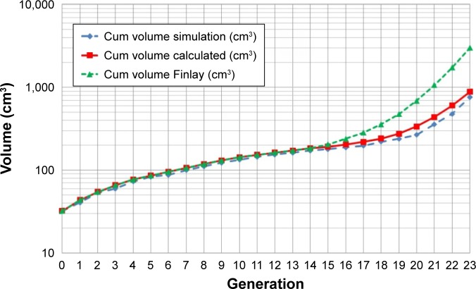
Figure 5 displays the lung volume accumulated along the generations. The volume which is not present in the air ducts is that of the alveolar space and is accounted for by out-flow boundary conditions.
Figure 5.
Cumulative lung volume of the air ducts in the present simulation model, of the theoretical calculated volume and of the volume provided by Finlay including alveoles as a function of the airway generation.
Note: Reprinted from The mechanics of inhaled pharmaceutical aerosols, Finlay WH, Copyright (2001), with permission from Elsevier.1
After the 3D representation of the airways was finalized, a volume mesh was created using the Tgrid mesh generator (ANSYS, Canonsburg, PA, USA). It consisted of 26,000,000 tetrahedral cells, and was converted in Fluent to 6,600,000 polyhedral cells. Figure 6 gives examples of the mesh uniformity and the element size in comparison with the dimensions of the air ducts. CFD was investigated applying Ansys Fluent Version 14.5 and Version 15 (ANSYS).
Figure 6.
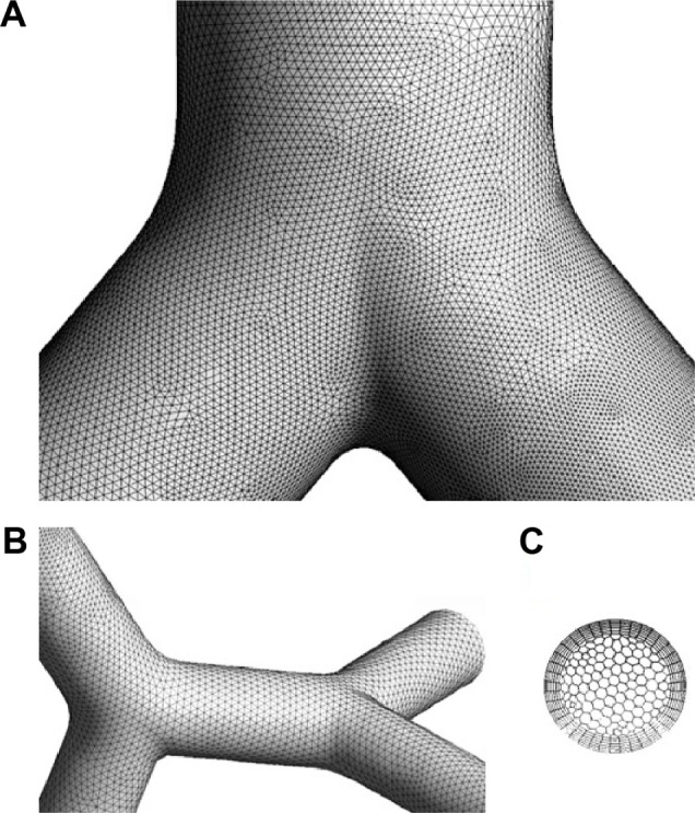
Visual appearance of the computer mesh used for the CFD calculation.
Notes: (A) Mesh of the constructed single path model at the first generation, (B) at the 22nd and 23rd generation, and (C) mesh at the outlet of the 23rd generation.
Underlying assumptions of the model calculation
Evaporation of aqueous droplets was considered improbable on their way from the trachea to the small airways, so this effect was not included in the CFD simulation. Hygroscopic effects which might increase the particle size in dry powders were neglected. Thus, the output particle size of the inhalers was not modified during the model calculation. As a single path was intended to be extrapolated to cover the whole lung, reference to an external coordinate system was deemed not appropriate, and therefore gravitational effects were excluded.
Results
NGI and filter measurements with throat model
Table 2 quantitatively documents the various throat deposition data. The output of the Alberta throat is the modeled mDTL which was assessed experimentally. For both breathing patterns, the results show that mDTL is maximized by Respimat.
Table 2.
Results of all filter and NGI measurements
| Respimat | Breezhaler | Genuair | Ellipta vil | Ellipta flu | |
|---|---|---|---|---|---|
| Moderate, COPD | |||||
| Inhaler (%ND) | 2.5 | 6.0 | 4.2 | NA | NA |
| SD | 0.7 | 0.2 | 0.2 | NA | NA |
| Throat (%ND) | 34.0 | 40.2 | 61.2 | 40.9 | 56.5 |
| SD | 5.9 | 0.6 | 1.9 | 3.5 | 1.4 |
| mDTL (%ND) | 59.2 | 42.5* | 31.8* | 48.8* | 33.2* |
| SD | 4.9 | 1.7 | 2.2 | 2.7 | 2.8 |
| DD (%ND) | 93.1 | 82.7 | 93.0 | 89.7 | 89.7 |
| SD | 3.3 | 2.2 | 3.2 | 2.4 | 1.5 |
| Very severe, COPD | |||||
| Inhaler (%ND) | 2.7 | 7.8 | 3.6 | NA | NA |
| SD | 1.5 | 1.1 | 0.2 | NA | NA |
| Throat (%ND) | 27.2 | 31.3 | 63.0 | 50.5 | 53.4 |
| SD | 8.7 | 2.9 | 1.6 | 2.3 | 2.4 |
| mDTL (%ND) | 67.4 | 51.1* | 41.9* | 55.0* | 40.7* |
| SD | 4.6 | 2.0 | 1.4 | 1.8 | 1.5 |
| DD (%ND) | 94.7 | 82.4 | 104.9 | 105.5 | 94.1 |
| SD | 4.1 | 2.2 | 1.2 | 2.8 | 1.1 |
| FPF (%ND) | 44.7 | 43.1 | 36.2 | 39.5 | 23.8 |
| SD | 6.1 | 2.4 | 1.6 | 1.9 | 1.7 |
| MMAD (μm) | 3.7 | 2.5 | 2.4 | 1.8 | 3.2 |
| SD | 0.5 | 0.1 | 0.03 | 0.1 | 0.2 |
Notes: n=3 repetitions.
Indicative for significantly different mDTL of very severe vs moderate COPD inhalation.
Abbreviations: DD, delivered dose; COPD, chronic obstructive pulmonary disease; FPF, fine particle fraction; MMAD, mass median aerodynamic diameter; NA, not available; ND, nominal dose; NGI, next generation impactor; mDTL, modeled dose to the lung; SD, standard deviation.
For the Respimat inhaler mDTL was found to be 59% (SD 5%) for the moderate COPD breathing pattern and 67% (SD 5%) for very severe COPD breathing pattern. The percentages refer to ND in vitro. Breezhaler showed a mDTL of 43% (SD 2%) for moderate disease simulation and 51% (SD 2%) for very severe simulation. The corresponding results for Genuair are mDTL of 32% (SD 2%) for moderate and 42% (SD 1%) for very severe states. Ellipta vilanterol particles showed a mDTL of 49% (SD 3%) for moderate and 55% (SD 2%) for very severe disease simulation, and Ellipta fluticasone particles showed a mDTL of 33% (SD 3%) and 41% (SD 2%), respectively, for moderate and very severe breathing patterns.
A significant difference in lung deposition concerning the two different breathing patterns (P-value of moderate vs very severe COPD pattern) was observed for all dry powder inhalers (Breezhaler, 0.0049; Genuair, 0.0026; Ellipta vilanterol, 0.031; Ellipta fluticasone, 0.0153), not for Respimat (P=0.0991, confidence interval 95%, two-sided t-test). The mDTL values of the tested APIs showed significant differences (0.0004<P<0.033) between the breathing patterns in the case of all inhaler combinations except for Genuair and Ellipta fluticasone which had very similar mDTLs for both breathing patterns. Breezhaler and Ellipta vilanterol showed very similar mDTLs only for the breathing pattern of very severe COPD (P=0.066).
In all five cases, the modeled mDTL was higher when the breathing pattern of very severe COPD patients was applied (Figure 7). The measured model throat deposition was highest for Genuair with 61%ND (SD 2%) and 63%ND (SD 2%), respectively, followed by Ellipta fluticasone with 57% (SD 1%) and with 53% (SD 2%), Table 2.
Figure 7.
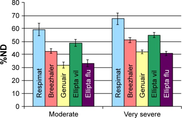
Modeled dose to the lung determined using the NGI setup (applied for very severe COPD breathing pattern) and the filter setup (for moderate COPD breathing pattern).
Notes: Blue, tiotropium (Respimat); red, glycopyrronium (Breezhaler); yellow, aclidinium (Genuair); green, vilanterol (Ellipta); and purple, fluticasone (Ellipta).
Abbreviations: COPD, chronic obstructive pulmonary disease; ND, nominal dose; NGI, next generation impactor.
Figure S1 provides a visual impression of the throat deposition and Figure S2 shows that throat deposition and mDTL complement each other (eg, very severe COPD breathing pattern).
CFD simulation
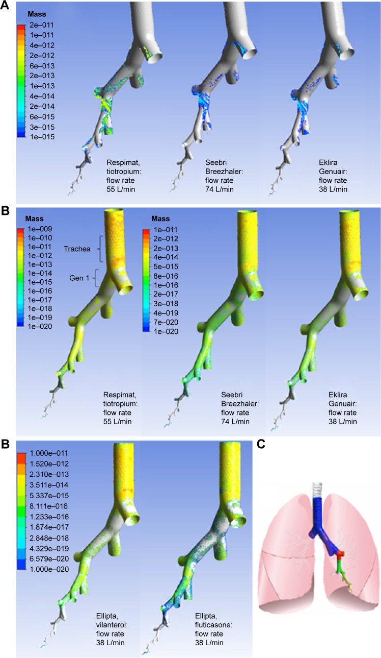
The effects of the inhaler-characteristics and formulation, for example, of particle size distribution, airflow velocity, and particle mass flow on the deposition pattern were compared. Figure 8 shows the geometry of the individual path model and the muscarinic receptor density color-coded on the surface of the model, as well as the particle deposition resulting from laminar and turbulent simulations considering impaction.
Figure 8.
Particle deposition results of CFD simulations and receptor densities.
Notes: (A) Laminar flow, (B) turbulent flow, and (C) densities of M1 and M3 muscarinic receptors. Blue, density not known; red, high density; green, low to medium density; yellow, medium to high density. Total modeled particle mass to the lung: Respimat droplets 7.9 mg (including water as a solvent), Breezhaler API particles 0.03 mg, Genuair API particles 0.16 mg, Ellipta vilanterol particles 0.12 mg, Ellipta fluticasone particles 0.37 mg.
Abbreviations: API, active pharmaceutical ingredient; CFD, computational fluid dynamics.
According to Figure 8A in the case of laminar flow, the particle deposition of aerosol from the four inhalers started quite low in the first 4 generations, then decreased even more in the 5th–14th, increased again from the 15th to the 19th generation and rose sharply between the 20th and the 23rd generation (Figure S3A).
For turbulent flow (Figure 8B), there is more deposition from trachea to generation 14 and less in generation 15–23 compared to the laminar flow simulation. This is valid for all tested inhaler aerosols. In reality gravitational settling enhances deposition in the higher generations which motivates pooling of the deposition results from generation 15 to the final alveoles (Figure S3A and B).
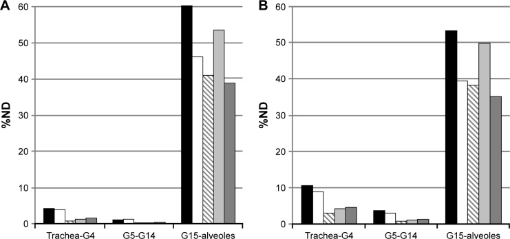
The resulting deposition patterns shown in Figure 9 were quite similar for Respimat, Breezhaler, and Ellipta vilanterol particles, but Respimat delivered more particle mass (%ND) to the different lung regions. Genuair and Ellipta fluticasone particles had the lowest overall deposition. Genuair showed the lowest deposition of all inhalers in the first 14 generations, while fluticasone particles were deposited in the lowest amount of all substances in the periphery (G15-alveoles).
Figure 9.
CFD simulation results, (A) laminar model, (B) turbulent model.
Notes: Simulated mass deposited in the whole lung as % of ND, Respimat, Breezhaler, Genuair, Ellipta vilanterol, and Ellipta fluticasone.
Abbreviations: CFD, computational fluid dynamics; ND, nominal dose.
Discussion
In this study, the hypothesis of different aerosol deposition of Respimat, Breezhaler, Genuair, and Ellipta were tested applying a breathing pattern driven setup based on the Alberta throat model. Aim was the comparison of the particle deposition in throat (experimental in vitro) and lung models (computed in silico). In short, a combination of an idealized throat model in vitro and a subsequent computational CFD deposition estimation in the lung was created.
NGI and filter measurements with throat model
Based on measured in vitro results, the three tested dry powder inhalers delivered a smaller percentage of the modeled mDTL of the API than the Respimat inhaler when relating to the ND as given by the label claim (Figure 7). Furthermore, the mDTL was reduced when the moderate COPD breathing pattern was used (Figure 7). On an average, the moderate COPD patient inhales more strongly than the patient suffering from very severe COPD, and the airflow velocity is higher. Due to this higher velocity, the aerosol particles could hardly follow the airflow through the throat and therefore they impacted in the mouth throat region.1 The deposition was clearly visible in our in vitro results (Figure S1). The mDTL values of the tested APIs showed significant differences (0.0004<P<0.033) between the breathing patterns in the case of all inhaler combinations except the comparisons of Genuair with Ellipta fluticasone (for both breathing patterns) and of Breezhaler with Ellipta vilanterol (for very severe breathing pattern). In the case of Genuair (aclidinium) and Ellipta (vilanterol), the in vitro results showed a lower overall delivered dose with the moderate breathing pattern than with the very severe breathing pattern (Table 2). This may be explained by over-or underfilled devices, as the delivered dose values were still in the range of 85%–115% of the label claim.
The flow rates of the applied breathing patterns were all in a quite optimal range for the tested DPI inhalers. The flow rates were higher than 30 L/min which is the minimum required air flow of most DPIs.24 Breezhaler requires a minimum flow rate of 30 L/min, while the optimal flow rate is 60 L/min.25 Genuair shows the optimal FPF at flows of >45 L/min.26
The active inhaler Respimat can also be used at lower flow rates, as its aerosol generation is independent of the air flow rate and consequently the deposition did not vary significantly (P=0.0991, 95% CI) between the two breathing patterns investigated.
The ideal particle size distribution for inhaled pharmaceutical aerosols is still under discussion. The deposition in the airways does not only depend on particle size, but it depends also on flow rate, timing of the inhalation, and airway geometry which all can vary considerably in patients.1 For example, Weda et al reported for salbutamol that a high FPF and a lot of small particles may cause side effects. Small particles with sizes of ~1.7 μm led to more side effects like lower K+-serum and increased heart rate whereas there was hardly any difference in therapeutic effect on FEV1.27
Howarth28 showed that a particle size of 2.8 μm was better for ipratropium and salbutamol than 1.5 or 5 μm concerning the positive effect on FEV1 and reduced side effects. A particle size of >5 μm up to 10 μm leads mainly to bronchial deposition and >10 μm the particles are filtered by the upper respiratory tract, namely the mouth–throat region as shown by model simulations. The MMAD values determined after passage of the mouth–throat model were given in Table 2. Specifically, the Respimat delivered the largest particles at the outlet of the throat model: MMAD =3.7 μm.
In contrast, the dry powder inhalers generated MMAD values between 1.8 μm (vilanterol) and 3.2 μm (fluticasone), whereas glycopyrronium (2.5 μm) and aclidinium (2.4 μm) were in a medium range. Because of the generally higher flow rate in DPIs which require fast inhalation for deagglomeration, the generation of particles with smaller diameters is essential for passing the mouth–throat region. Once the small particles have passed the glottis, they follow the airways toward the periphery and deposition takes place in higher generations, provided the inhalation maneuver is carried out correctly.
CFD model
Comparing the single path model to Finlay’s publication, similar volumes for generation 0–15 were found (Figure 5). Regarding generations 15–23 the air ducts in the present lung model had a lower volume compared to Finlay’s lung. Starting from generation 15, the alveolar volume is known to contribute to the lung volume. In our model, the contribution of alveoles and alveolar sacs was considered by boundary conditions defining an appropriate air outflow for each individual generation. This eliminated the need for any individual geometric representations of the volume of alveoles. An alternative realized, for example, by the COPHIT project might be the use of a Windkessel model.29 Because our model approach employs simplifications which stimulate further discussions but are not accessible to direct experimental investigations, the quantitative comparison in Figure 9 is limited to generation 14. The remainder of deposited material is pooled. A more detailed analysis is presented in Figure S3A and B. Two flow models were compared in this study, a model with laminar airflow and constant inlet profile and a LRN k–ω-SST turbulence model with a turbulent inflow of particles into the trachea, as these in silico methods were found to match experimental data of Oldham et al30 best. A small difference was motivated by a different turbulent inlet profile compared to the study by Longest and Vinchurkar.14
Symmetric outflow conditions at the two ends of all bifurcations were applied, such as proposed by Longest and Vinchurkar.14 This was only an approximation and it provided one typical path of an idealized healthy lung.
Interpretation of CFD results
Our findings in the CFD simulation showed that there is deposition deep in the lung for all four inhaler aerosols, starting already in the alveolar ducts. It is likely that alveolar deposition in generations >20 was overestimated in our simulation, especially in case of the laminar flow condition. The advantage of the present model is the side by side comparison of the aerosol distributions in the different lung regions. In the literature, the deposition efficiency of every single generation in comparison to the others in the same simulation was mainly depending on the diameter of the airway.1
Comparison with in vivo scintigraphy studies
For Breezhaler and Relvar Ellipta there is no scintigraphic in vivo data available, but for Respimat and Genuair scintigraphic deposition data on total lung deposition agreed well with our in vitro results (Table 2; Figures 8 and 9).
Brand et al31 found for Respimat in trained patients a scintigraphic dose of 53%DD (SD 17%DD), whereas 25%DD (SD 10%DD) were delivered to the central airways, 18%DD (SD 6%DD) to the intermediate and 10%DD (SD 3%DD) to the peripheral (small) airways. In addition, Brand et al32 found 44%–63% lung deposition (at inhalation flow rates of 60 and 15 L/min) and 34%–50% throat deposition (at flow rates of 15 and 60 L/min).
Our findings were a mDTL of 59%ND (SD 5%ND, moderate COPD) resp 67%ND (5%ND, very severe COPD) which corresponded well to the above in vivo data.
Figure 9 depicts for Respimat that the laminar simulation showed a deposition of 4% for Generation (Gen) 0–4, 1% for Gen 5–14, and 63% for Gen 15-alveolar sacs. The turbulent simulation showed a deposition of 11% for Generation 0–4, 4% for Gen 5–14, 9% and 54% for Gen 14-alveolar sacs.
The in silico results describing the local distribution are difficult to compare to in vivo scintigraphic 2D images. On these types of pictures, it is almost impossible to separate deposition by generation number. The deposition in the more central airways is often overestimated as small airways that are lying in front and on the back side of the large central airways will be counted to the central group. Meanwhile, alveolar deposition is underestimated. Furthermore, our model underestimated central deposition as the geometry was very smooth and did not contain cartilaginous rings which alter the shape of the airways and could have enhanced deposition by increased turbulence.
For the Respimat prototype III Newman et al33 found a different lung deposition pattern: in the central lung zone 10%MD (SD 3%MD) were deposited, in the intermediate zone 15%MD (SD 4%MD), and in the peripheral zone 14%MD (SD 4%MD) whereas the MDI delivered only 5%MD (SD 2%MD), 5%MD (SD 2%MD), and 5%MD (SD 1%MD) in these 3 zones. These results for Respimat do not match our simulation study because our peripheral zone ranged from generation 15 to the alveoles and, therefore, comprised a much larger part of the lung.
Newman et al34 found for Genuair a whole lung deposition of 30%MD (SD 7%MD) which compared very well to our findings. Deposition in the oropharynx was found to be 55%MD (SD 7%MD; which is also in agreement to our findings). There were 10%MD deposited in the most central lung zone, and 3%MD in the most peripheral (~4%–5% in the four middle lung zones between). However, more active ingredient was deposited in the central airways than in the peripheral airways while in our simulation (laminar and turbulent flow) it was the other way around. For example, the turbulent flow simulation showed a deposition of 3, 1, 6, and 32%ND from central to peripheral airways (Figure S3B, Genuair).
Comparison of deposition site and muscarinic receptor density
According to Ikeda et al there is a very low density of M1 receptors in the first generations increasing until the 23rd and a high density of M3 receptors in the 3rd generation decreasing until the 23rd generation (Table S1 and study by Ikeda et al18). The amount of submucosal glands which are targets for muscarinic antagonists is high in the large airways and decreases with generation number. Smooth muscles that are also targets for muscarinic antagonists show a completely different distribution pattern in the lungs as their amount is relatively low in the large airways, it is increasing until the bronchioles and they are not present in the alveoli. By definition “small airways” with a diameter of <2 mm exist between generation 10 and 23. They get blocked more easily by extensive mucus secretion and wall thickening because of lung repair or remodeling.35
According to the simulation (Figure 9; Figure S3A and B) all aerosols were deposited to the highest extent in the small airways that have alveoli and alveolar sacs (15th–23rd generation, increasing with each further generation). There was very little deposition in the 5th–14th generation for all four aerosols.
The Respimat and Breezhaler aerosol deposition simulations showed high deposition in the 3rd, 4th, and in the 15th–23rd generation. This deposition pattern fitted quite well to the distribution of muscarinic receptors in the lung. In contrast to the Respimat and Breezhaler aerosols on the one hand, the Genuair and Ellipta (both, vilanterol and fluticasone) aerosols showed very low particle deposition and deposition efficiencies in the first generations (1st–14th, Figure 8; Figure S3A and B). Calculated deposition in the smaller airways (Gen 15 – alveoles) was in the 30%–50% range. Interestingly, the model predicted the lowest relative deposition in the lung periphery for fluticasone.
The deposition pattern in the 23 generations of the idealized single-path in silico lung model visually seemed to be similar for Respimat and Ellipta (Figure 8), but numerical evaluations revealed that Respimat delivered more relative particle mass (%ND) to the upper airways than Ellipta, and at the same time, Respimat provided the highest relative deposition in the periphery (Figure 9).
Limitations of the combined in vitro–in silico model
A number of restrictions of our study and areas for future research should be mentioned: the obvious limitations of in vitro studies such as the present one are the simplification of the throat model (it might be useful to generate data based on a set of models), the modeling of the inhalation flow profile (the patient-induced variability is evident), and the selection of CFD methods which all influence the final results.
In silico, assumptions were made for particle density, idealized lung geometry including branching angles. The detailed geometry of alveoles was simplified by applying boundary conditions called outflow and sink. The deposition in generations 15–23 may be overestimated because all particles that flow into the sink were trapped. Exhalation and breath-holding were not accounted for. Furthermore, our model neglected Brownian motion, sedimentation through gravitation and particle-to-particle collision. Deposition in the 8th–14th generation seemed to be underestimated which may be due to the assumption of symmetric branching.
Furthermore, numerical simulations are needed, for example, a simulation of the lung with mouth–throat geometry and with more branches because in nature the flow and the deposition are asymmetrical. This can influence the flow and deposition pattern.36 Another simulation with instationary flow would be useful. The effect of different branching angles could be studied, too. At present, the prediction of the therapeutic effectiveness can be made only based on in vivo studies and bridging from deposition data to clinical effects has just started.37
Conclusion
In summary, the comparison of the different inhalers is possible and the main influencing mechanism seems to be throat deposition due to different flow resistances and operation principles, which in turn influence the patients’ inhalation flow profiles. Apart from different disease-specific flow profiles, the effects of the patient’s disease (bronchoconstriction, reduced or even blocked air exchange in parts of the lung, fate of drug particles after deposition, clearance) are not assessed. However, for the purpose of comparison of inhalers, the setting may provide high reproducibility and therefore enable the detection of minute differences between inhaled products.
The combined in vitro and in silico results for Respimat show the lowest throat deposition and at the same time the highest deposition in the whole lung and in the different lung generations in comparison to the DPIs. The model investigations predict that the Respimat droplets deposit in a more uniformly distributed way in the different lung regions compared to dry powder particles of the investigated inhalers.
Future trends
In vitro test systems and CFD simulations are needed that can accurately predict total lung dose delivered from a number of inhalers including pMDIs, pMDIs with spacers, DPIs, and nebulizers. Especially in children, where ethical reasons prohibit many clinical studies, pediatric throat models and computational simulations will support the development of better delivery systems.
3D human lung models, based on CT-data from real patients, and when combined with a pharmacokinetic simulation, could help decrease the number of preclinical and clinical studies. Such models could also decrease the number of human subjects needed in Phase I trials and reduce the need for scintigraphic deposition studies.
Acknowledgments
We thank Prof Warren Finlay for providing the idealized throat geometry. Ralf Kröger (ANSYS Germany) supported the CFD simulations. Poster presented at the ISAM 2013 Conference, Chapel Hill, NC, USA, April 06–10, 2013 and at the ISAM 2015 Conference, Munich, Germany, May 30–June 3, 2015.38,39 The abstract has been published in Pneumologie 2014; 68 – P568 and in Journal of Aerosol Medicine and Pulmonary Drug Delivery. Jun 2015: A-33: (http://online.liebertpub.com/doi/pdfplus/10.1089/jamp. 2015.ab01.abstracts).40
Footnotes
Disclosure
AC conducts a thesis sponsored by Boehringer Ingelheim (BI), the manufacturer of the Respimat inhaler. HW is an employee of BI. PL is consultant to BI. The authors report no other conflicts of interest in this work.
References
- 1.Finlay WH. The mechanics of inhaled pharmaceutical aerosols. San Diego, CA: Academic Press Inc; 2001. [Google Scholar]
- 2.Johnstone A, Uddin M, Pollard A, Heenan A, Finlay WH. The flow inside an idealised form of the human extra-thoracic airway. Experiments Fluids. 2004;37(5):673–689. [Google Scholar]
- 3.Olsson B, Borgstrom L, Lundback H, Svensson M. Validation of a general in vitro approach for prediction of total lung deposition in healthy adults for pharmaceutical inhalation products. J Aerosol Med Pulm Drug Deliv. 2013;26(6):355–369. doi: 10.1089/jamp.2012.0986. [DOI] [PubMed] [Google Scholar]
- 4.Wachtel H, Bickmann D, Breitkreutz J, Langguth P. Can pediatric throat models and air flow profiles improve our dose finding strategy?; Paper presented at: Respiratory Drug Delivery; April 25–29, 2010; Orlando, Florida, USA. [Google Scholar]
- 5.Wachtel H, Flüge T, Gössl R. Flow – pressure – energy – power: which is the essential factor in breathing patterns of patients using inhalers?; Paper presented at: Respiratory Drug Delivery; April 23–27, 2006; Boca Raton, Florida, USA. [Google Scholar]
- 6.Global Strategy for Diagnosis, Management, and Prevention of COPD. 2005. [Accessed December 1, 2005]. Available from: http://www.goldcopd.org.
- 7.Horsfield K, Cumming G. Morphology of the bronchial tree in man. J Appl Physiol. 1968;24(3):373–383. doi: 10.1152/jappl.1968.24.3.373. [DOI] [PubMed] [Google Scholar]
- 8.Raabe O, Yeh H, Schum G, Phalen R. Tracheobronchial geometry: human, dog, rat, hamster – a compilation of selected data from the project respiratory tract deposition models. U.S. Energy Research and Development Administration, Division of Biomedical and Environmental Research; 1976. [Google Scholar]
- 9.Haefeli-Bleuer B, Weibel ER. Morphometry of the human pulmonary acinus. Anat Rec. 1988;220(4):401–414. doi: 10.1002/ar.1092200410. [DOI] [PubMed] [Google Scholar]
- 10.Finlay WH, Lange CF, King M, Speert DP. Lung delivery of aerosolized dextran. Am J Respir Crit Care Med. 2000;161(1):91–97. doi: 10.1164/ajrccm.161.1.9812094. [DOI] [PubMed] [Google Scholar]
- 11.Tian G, Longest PW, Su G, Hindle M. Characterization of respiratory drug delivery with enhanced condensational growth using an individual path model of the entire tracheobronchial airways. Ann Biomed Eng. 2011;39(3):1136–1153. doi: 10.1007/s10439-010-0223-z. [DOI] [PMC free article] [PubMed] [Google Scholar]
- 12.Mead-Hunter R, King AJC, Larcombe AN, Mullins BJ. The influence of moving walls on respiratory aerosol deposition modelling. J Aerosol Sci. 2013;64:48–59. [Google Scholar]
- 13.Weibel ER. Morphometry of the human lung: the state of the art after two decades. Bull Eur Physiopathol Respir. 1979;15(5):s999–s1013. [PubMed] [Google Scholar]
- 14.Longest PW, Vinchurka S. Validating CFD predictions of respiratory aerosol deposition: effects of upstream transition and turbulence. J Biomech. 2007;40(2):305–316. doi: 10.1016/j.jbiomech.2006.01.006. [DOI] [PubMed] [Google Scholar]
- 15.Longest PW, Holbrook LT. In silico models of aerosol delivery to the respiratory tract – Development and applications. Adv Drug Deliv Revs. 2012;64(4):296–311. doi: 10.1016/j.addr.2011.05.009. [DOI] [PMC free article] [PubMed] [Google Scholar]
- 16.Barnes PJ. Distribution of receptor targets in the lung. Proc Am Thorac Soc. 2004;1(4):345–351. doi: 10.1513/pats.200409-045MS. [DOI] [PubMed] [Google Scholar]
- 17.Mak JC, Barnes PJ. Autoradiographic visualization of muscarinic receptor subtypes in human and guinea pig lung. Am Rev Respir Disss. 1990;141(6):1559–1568. doi: 10.1164/ajrccm/141.6.1559. [DOI] [PubMed] [Google Scholar]
- 18.Ikeda T, Anisuzzaman AS, Yoshiki H, et al. Regional quantification of muscarinic acetylcholine receptors and β-adrenoceptors in human airways. Br J Pharmacol. 2012;166(6):1804–1814. doi: 10.1111/j.1476-5381.2012.01881.x. [DOI] [PMC free article] [PubMed] [Google Scholar]
- 19.De Backer JW, Vos WG, Vinchurkar SC, et al. Validation of computational fluid dynamics in CT-based airway models with SPECT/CT. Radiology. 2010;257(3):854–862. doi: 10.1148/radiol.10100322. [DOI] [PubMed] [Google Scholar]
- 20.Barnes PJ, Basbaum CB, Nadel JA. Autoradiographic localization of autonomic receptors in airway smooth muscle. Marked differences between large and small airways. Am Rev Respir Dis. 1983;127(6):758–762. doi: 10.1164/arrd.1983.127.6.758. [DOI] [PubMed] [Google Scholar]
- 21.van Koppen CJ, Rodrigues de Miranda JF, Beld AJ, Hermanussen MW, Lammers JWJ, van Ginneken CAs. Characterization of the muscarinic receptor in human tracheal smooth muscle. Naunyn Schmiedeberg’s Arch Pharmacol. 1985;331(2–3):247–252. doi: 10.1007/BF00634245. [DOI] [PubMed] [Google Scholar]
- 22.Zanker D, Cuoghi E, Singh D, Ehlich H, Sommerer K, Jauernig J. In Vitro Dose Delivery Performance of Glycopyrronium using Representative Inspiratory Flow Profiles derived from COPD Patients; Paper presented at: Drug Delivery to the Lungs; December 5–7, 2012; Edinburgh, UK. [Google Scholar]
- 23.Maggio RM, Vignaduzzo SE, Kaufman TS. Practical and regulatory considerations for stability-indicating methods for the assay of bulk drugs and drug formulations. Trends Anal Chem. 2013;49:57–70. [Google Scholar]
- 24.Voshaar T, App EM, Berdel D, et al. Arbeitsgruppe Aerosolmedizin der Deutschen Gesellschaft für Pneumologie Recommendations for the choice of inhalatory systems for drug prescription. Pneumologie. 2001;55(12):579–586. doi: 10.1055/s-2001-19003. German. [DOI] [PubMed] [Google Scholar]
- 25.Kuttler A, Dimke T. A Novel biophysical simulation model of drug deposition implemented to predict and optimize Qva149 delivery to the lungs; San Diego: Paper presented at: ATS; 2014. [Google Scholar]
- 26.Magnussen H, Watz H, Zimmermann I, et al. Peak inspiratory flow through the Genuair-inhaler in patients with moderate or severe COPD. Respir Med. 2009;103(12):1832–1837. doi: 10.1016/j.rmed.2009.07.006. [DOI] [PubMed] [Google Scholar]
- 27.Weda M, Zanen P, Boer AH, Barends DM, Frijlink HW. An investigation into the predictive value of cascade impactor results for side effects of inhaled salbutamol. Int J Pharmaceutics. 2004;287(1–2):79–87. doi: 10.1016/j.ijpharm.2004.08.017. [DOI] [PubMed] [Google Scholar]
- 28.Howarth PH. Why particle size should affect clinical response to inhaled therapy. J Aerosol Med. 2001;14(Suppl 1):S27–S34. doi: 10.1089/08942680150506312. [DOI] [PubMed] [Google Scholar]
- 29.Wilson AJ, Murphy CM, Brook BS, Breen D, Miles AW, Tilley DG. A computer model of the artificially ventilated human respiratory system in adult intensive care. Med Eng Phys. 2009;31(9):1118–1133. doi: 10.1016/j.medengphy.2009.07.009. [DOI] [PubMed] [Google Scholar]
- 30.Oldham MJ, Phalen RF, Heistracher T. Computational fluid dynamic predictions and experimental results for particle deposition in an airway model. Aerosol Sci Technol. 2000;32(1):61–71. [Google Scholar]
- 31.Brand P, Hederer B, Austen G, Dewberry H, Meyer T. Higher lung deposition with Respimat Soft Mist inhaler than HFA-MDI in COPD patients with poor technique. Int J COPD. 2008;3(4):763–770. [PMC free article] [PubMed] [Google Scholar]
- 32.Brand P, Hederer B, Loewe L, Herpich S, Haeussermann S, Sommer K. Flow dependency of lung deposition after inhalation with a HFA-pMDI and the Respimat® Soft Inhaler in COPD patients. Pneumologie. 2007;61:127. [Google Scholar]
- 33.Newman SP, Steed KP, Reader SJ, Hooper G, Zierenberg B. Efficient delivery to the lungs of flunisolide aerosol from a new portable handheld multidose nebulizer. J Pharm Sci. 1996;85(9):960–964. doi: 10.1021/js950522q. [DOI] [PubMed] [Google Scholar]
- 34.Newman SP, Sutton DJ, Segarra R, Lamarca R, De Miquel G. Lung deposition of aclidinium bromide from Genuair, a multidose dry powder inhaler. Respiration. 2009;78(3):322–328. doi: 10.1159/000219676. [DOI] [PubMed] [Google Scholar]
- 35.Stewart JI, Criner GJ. The small airways in chronic obstructive pulmonary disease: pathology and effects on disease progression and survival. Curr Opin Pulm Med. 2013;19(2):109–115. doi: 10.1097/MCP.0b013e32835ceefc. [DOI] [PubMed] [Google Scholar]
- 36.Balashazy I, Hofmann W. Deposition of aerosols in asymmetric airway bifurcations. J Aerosol Sci. 1995;26(2):273–292. [Google Scholar]
- 37.Borghardt JM, Weber B, Staab A, Kunz C, Schiewe J, Kloft C. Expanding the mechanistic knowledge about pulmonary absorption processes using a population pharmacokinetic model for inhaled olodaterol; Paper presented at: Respiratory Drug Delivery; May 4–8, 2014; Fajardo, Puerto Rico, USA. [Google Scholar]
- 38.Ciciliani AM, Langguth P, Bickmann D, Wachtel H, Voshaar T. In vitro dose comparison of respimat soft mist inhaler with dry powder inhalers for copd maintenance therapy; Paper presented at: 19th ISAM Congress; April 6–10; 2013; Chapel Hill, North Carolina, USA. [Google Scholar]
- 39.Ciciliani AM, Wachtel H, Langguth P. Respimat soft mist inhaler shows higher in vitro deposition performance compared to other copd inhalers; Paper presented at: 20th ISAM Congress; May 30–June 3; 2015; Munich, Germany. [Google Scholar]
- 40.Ciciliani AM, Wachtel H, Langguth P. Respimat soft mist inhaler shows higher in vitro deposition performance compared to other copd inhalers. J Aerosol Med Pulm Drug Deliv. 2015;28(3):A33–A33. [Google Scholar]
- 41.Spiriva Respimat OKed for COPD in Europe thepharmaletter. 2007. [Accessed November 29, 2016]. Available from: http://www.thepharmaletter.com/article/spiriva-respimat-oked-for-copd-in-europe.
- 42.Asthma: new indication for Spiriva® (tiotropium) Respimat®* in the EU. [Accessed December 3, 2016]. (Boehringer Ingelheim press release; 2014). Available from: https://www.boehringer-ingelheim.com/press-release/asthma-new-indication-spiriva-tiotropium-respimat-eu-may-offer-millions-adults.
- 43.Seebri Breezhaler. Summary for the Public. 2012. [Accessed July 12, 2015]. Available from: http://www.ema.europa.eu/docs/de_DE/document_library/EPAR_-_Summary_for_the_public/human/002430/WC500133772.pdf.
- 44.Eklira Genuair. Summary for the public. 2013. [Accessed July 12, 2015]. Available from: http://www.ema.europa.eu/docs/de_DE/document_library/EPAR_-_Summary_for_the_public/human/002211/WC500132664.pdf.
- 45.RELVAR® ELLIPTA® receives European marketing authorisation for the treatment of asthma and COPD. [Accessed November 11, 2016]. (GSK press release; 2013). Available from: http://www.gsk.com/en-gb/media/press-releases/2013/relvar-ellipta-receives-european-marketing-authorisation-for-the-treatment-of-asthma-and-copd/
- 46.FDA Approves Anoro Ellipta. 2013. [Accessed February 19, 2015]. Drugs.com. Available from: http://www.drugs.com/newdrugs/fda-approves-anoro-ellipta-chronic-obstructive-pulmonary-3992.html.
- 47.GSK receives approval for Incruse™ Ellipta® (umeclidinium) in the US for the treatment of COPD. [Accessed November 29, 2016]. (GSK press release; 2014). Available from: http://us.gsk.com/en-us/media/press-releases/2014/gsk-receives-approval-for-incruse-ellipta-umeclidinium-in-the-us-for-the-treatment-of-copdandnbsp/


