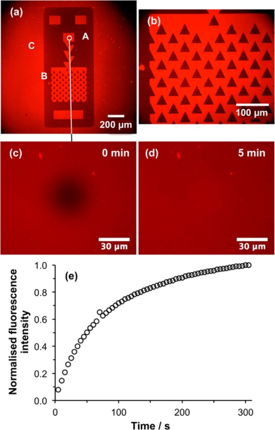
Figure 5.

(a,b) Fluorescence micrographs of a trap structure formed by UV exposure of a CMPTS film, ATRP of OEGMEMA and SLB deposition. Areas masked during UV light (for example the region marked A in panel a) support growth of POEGMEMA by ATRP, and thus resist SLB formation, while exposed regions such as B are polymer-free and facilitate SLB formation. The laser spot used during patterning was somewhat larger than the dimensions of the trap structure defined by the photolithography mask, hence removal of halogen also occurs outside the trap structure, enabling formation of an SLB there (e.g., at C). (c) Fluorescence micrograph showing a bleached spot formed in the small circular region identified in panel a. (d) Fluorescence micrograph of the same region acquired after 5 min. (e) Variation in fluorescence intensity in the bleached region as a function of time after exposure.
