Abstract
Introduction
In radiotherapy, megaelectron volt (MeV) electrons are employed for treatment of superficial cancers. Magnetic fields can be used for deflection and deformation of the electron flow. A magnetic field is composed of non-uniform permanent magnets. The primary electrons are not mono-energetic and completely parallel. Calculation of electron beam deflection requires using complex mathematical methods. In this study, a device was made to apply a magnetic field to an electron beam and the path of electrons was simulated in the magnetic field using finite element method.
Methods
A mini-applicator equipped with two neodymium permanent magnets was designed that enables tuning the distance between magnets. This device was placed in a standard applicator of Varian 2100 CD linear accelerator. The mini-applicator was simulated in CST Studio finite element software. Deflection angle and displacement of the electron beam was calculated after passing through the magnetic field. By determining a 2 to 5cm distance between two poles, various intensities of transverse magnetic field was created. The accelerator head was turned so that the deflected electrons became vertical to the water surface. To measure the displacement of the electron beam, EBT2 GafChromic films were employed. After being exposed, the films were scanned using HP G3010 reflection scanner and their optical density was extracted using programming in MATLAB environment. Displacement of the electron beam was compared with results of simulation after applying the magnetic field.
Results
Simulation results of the magnetic field showed good agreement with measured values. Maximum deflection angle for a 12 MeV beam was 32.9° and minimum deflection for 15 MeV was 12.1°. Measurement with the film showed precision of simulation in predicting the amount of displacement in the electron beam.
Conclusion
A magnetic mini-applicator was made and simulated using finite element method. Deflection angle and displacement of electron beam were calculated. With the method used in this study, a good prediction of the path of high-energy electrons was made before they entered the body.
Keywords: Linear accelerator, Electron beam, Magnetic field, NdFeb, Particle tracking simulation
1. Introduction
The Megaelectron volt (MeV) electron beam produced by linear accelerators is used to treat skin and chest wall cancer, boost the dose in photon therapy, and treat some head and neck tumors (1). Properties of an electron beam are uniform dose distribution in the target volume and rapid dose reduction after the treatment area. Electrons are deflected in the magnetic field affected by Lorentz force; therefore, the magnetic field can be employed to change dose distribution in the target tissue. In the 1950s, the use of a magnetic field was proposed to direct and increase the effective depth of electron beams (2). Whitmire et al. changed dose distribution in tissue equivalent phantom applying a 1Tesla magnetic field (3). Later, several studies were conducted on the effect of the magnetic field on the electron beam such that Bacchetti proposed the use of this system as an alternative for expensive treatments with heavy ions, considering creation of a peak similar to Bragg peak (4). Papiez has also introduced sweeping very high-energy electrons on tissues using a magnetic field as a substitute for intensity modulated radiation therapy (IMRT) (5). In calculating dose distribution under the influence of a magnetic field, precise calculation of electron interactions in the tissue was mainly focused on, and accurate calculation of magnetic field and particle tracking is less noticed. In some studies, to reduce the complexity of calculations, the magnetic field is supposed to be uniform (6, 7) or simple polynomial equations are used (8, 9). In addition, in these simulations, the electron beam is typically considered as a parallel and mono-energetic beam (7, 10). However, in reality the magnetic field created by a magnet is non-uniform and the inlet electron beams are not fully parallel and mono-energetic. Understanding the behavior and amount of electron deflection requires using more complex mathematical methods. In this study a magnetic mini-applicator was designed and manufactured that can be easily installed on linear accelerators and it changes the path of electrons by applying a magnetic field. In addition, a model was simulated and evaluated to predict the path of electrons in the magnetic field using finite element method.
2. Material and Methods
2.1. Research design
Designing and manufacturing the magnetic applicator and simulation of the magnetic field was conducted in the Medical Physics Department of Ahvaz Jundishapur University of Medical Sciences during 2015–2016. Measurements and validation of the simulated model were conducted in the Radiography Department of Golestan Hospital in Ahvaz, Iran in 2016.
2.2. Manufacturing Magnetic Mini-Applicator and Measurement of the Intensity of Magnetic Field
To make a magnetic field, neodymium iron boron (NdFeB) permanent magnets, Grade N35, were used with dimensions of 2×5×6 cm. These super magnets create a very strong magnetic field relative to their small size (11) such that they may be drawn towards the adjacent ferromagnetic objects and damage accelerator components and the user. A magnetic mini-applicator with two aluminum holders was made for safe placement of the magnet. As the distance between two poles changed, various intensities of magnetic field were created. The employed parts were non-magnetic to make the lowest amount of disturbance in the field. This mini-applicator was placed inside the standard applicator of a Varian 2100 CD therapeutic linear accelerator easily and safely for the device and user. Intensity of the magnetic field was measured using a 410 gaussmeter manufactured by Brockhaus with precision of 1millitesla. To prevent unwanted handshakes during measurement, a simple tool was made for millimeter transferring of the gaussmeter in two dimensions. The distance between two poles of the magnet was set on different values and by repeated displacement of the sensor, intensity of the magnetic field in various points inside and outside the space of magnet was measured point-to-point.
2.3. Simulation of Mini-Applicator’s Magnetic Field
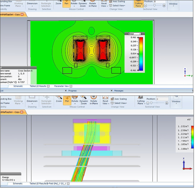
Non-uniformity of magnetic fields, and non-uniform spatial distribution, make the prediction of particles’ paths very difficult based on Lorentz equations. An effective method to solve such complex problems is the finite element method. To calculate the magnetic field and estimate the path of electrons, CST Studio Suite 2015 simulator software was used. This is among the most powerful software in the field of numerical simulation of electro-magnetic fields from low frequency to high frequency regions. This software is extraordinary for designing, analysis, 3D observation and particle tracking (12). The geometry of applicator components include aluminum holders, peripheral frame, cerrobend shield that limits the radiation field size, standard lead frame and also, protective plastic layers were modeled in the software. Density, electrical conductivity coefficient, magnetic permeability and permittivity of materials entered the software and an appropriate spatial mesh was considered. Properties of the magnet were supplied by the manufacturer (13). Magnetic remanence, Br, i.e. the maximum magnetic field that a magnet can produce in a closed cycle, is an important parameter in calculation of intensity of the magnetic field. Br varies among various grades of the magnet and also in various samples of a grade. Simulation was conducted using a default value for magnetic remanence, Br, (1.23T) based on information provided by the manufacturer (Figure 1 above), and magnetic field curve was extracted in orthogonal directions. The value of magnetic remanence changed frequently to determine the best Br value for which the results of calculations were matched with practical measurements.
Figure 1.
A schematic of simulated non-uniform magnetic field of mini-applicator in CST Studio software. Equi-intensity curves of magnetic field were plotted (above). 12MeV electron beam’s tracking and its deflection are displayed in the model (below). Colors indicate differences in the electrons’ velocities.
2.4. Estimation of the Electrons’ Path from Varian 2100CD Linear Accelerator in Magnetic Field
In the section of simulating particle transport in CST Studio Software, an electron source was considered above the mini-applicator. Details of the electron beam of the Varian 2100 CD linear accelerator were extracted as they entered the model from Monte Carlo’s previous study (14). Average energy for an electron beam with nominal energy of 12 and 15 MeV was considered to be 12.1 MeV (with 7.04% width of energy) and 15.35 MeV (with 6.05% width of energy) respectively. Angular divergence of both beams was determined to be 0.5. Particle’s monitor planes were considered perpendicular to Z direction under the mini-applicator frame. After simulation, coordinates of impact position and velocity components of electrons on these planes were extracted. Simulation of electron tracking in the magnetic field (Figure 1) was conducted for various distances of two poles and electrons’ deflection angle was calculated after passing the magnetic field. As a complex condition, the model was rotated around the accelerator isocenter to the calculated deflection angle. Therefore, electrons again became perpendicular to the phantom surface and therefore measurement of various parameters and model assessment was conducted more precisely. The accelerator isocenter was defined at collision point of initial axis of the beam with the plane of Source-Skin Distance (SSD) = 100 cm. By applying the magnetic field and rotation of device, the beam axis was displaced relative to the initial central axis as shown in Figure 2. In the simulated model, displacement was calculated from the position of electrons’ collision on the SSD = 105 plane.
Figure 2.
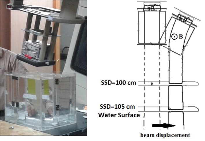
Mini-applicator placement inside the standard applicator of linear accelerator. Linear accelerator’s head has been rotated to make electrons perpendicular to the water surface (left). A geometric description of the head rotation, applying the magnetic field and displacement of the central axis (right).
2.5. Practical Evaluation of Electron Beam Tracking in the Magnetic Field
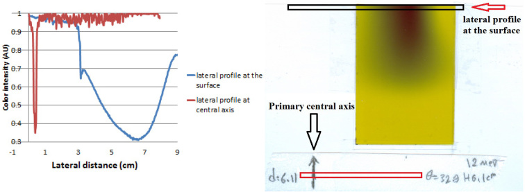
To practically evaluate precision of particle tracking in simulation, EBT2 GafChromic films were used. High spatial resolution, high sensitivity, wide response range and being tissue equivalent are of properties of these films. These films have low sensitivity to moisture and they can directly be placed in water during dosimetry; therefore, it is not required to use water equivalent solid phantoms (15). A rectangular piece of film was installed on a U-shaped base made of PMMA and it was completely submerged in water, such that the film was perpendicular to water surface in line with the central axis of exposure. The film edge was tangential to water surface and initial central axis (where the optical index of the field center is placed) was marked on the film. A magnetic mini-applicator was placed on the way of the electron beam of the Varian 2100 CD accelerator, and by putting a Cerrobend shield on the mini-applicator, the electrons’ path were restricted to a square with 3cm sides. SSD increased to 105 cm to prevent collision of the end of the applicator to the water’s surface while the device head is rotating. By changing the distance between two poles of the magnet, various intensities of transverse magnetic field were created. As can be seen in Figure 2, for each intensity of the magnetic field, the accelerator’s head was rotated for the deflection angle calculated in simulation to make electrons’ path perpendicular to the water surface again. Films were exposed to 3 Gy, and 48 hours after exposure, they were scanned using Flatbed HP G3010 reflective scanner with color depth of 24 bit and resolution of 127 dpi (5 pixels per millimeter). Color intensity in the red channel was extracted using programming in MATLAB 2012. Lateral profile curves of color intensity were extracted at the surface and depth of maximum dose. Amount of displacement of electron beam axis relative to the marked initial central axis was measured (Figure 3). To evaluate particle tracking in simulations, this amount of displacement was compared to the value calculated in simulation.
Figure 3.
Electron beam displacement relative to initial central axis sign (right). Lateral profiles of color intensity on the surface were compared with profiles on initial central axis mark (left).
3. Results
3.1. Measuring the Intensity of the Magnetic Field Created by Mini-Applicator
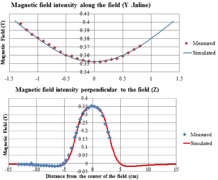
Intensity of the magnetic field perpendicular to the field reduced as it distanced the center (Figure 4). Outside the applicator, in distances close to the magnet, a magnetic field was observed inverse to the main field with much lower intensity that inclined to zero as it distanced the applicator. Polynomial and other common equations could not concurrently have a good fitness on intensity of the field in internal and external sector of applicator. This emphasized the necessity of magnetic field simulation using numerical methods. Intensity of the magnetic field relatively reached zero in the phantom level; therefore, there was no concern for the effect of the field on dose measurement. On the other hand, the effect of the magnetic field on upper parts of accelerator like the ionization chamber could also be neglected. Figure 4 shows data of measuring the magnetic field along N-S (Inline, Y). Intensity of the field decreased in this direction as it distanced the magnet and approached the center. Measurements along orthogonal directions showed that a sort of saddle shaped equation governs the set of measurements inside the applicator.
Figure 4.
A comparison of simulated and measured values of magnetic field along orthogonal axes (the distance between the two poles was 3.2 cm).
3.2. Results of Simulating Mini-Applicator Magnetic Field
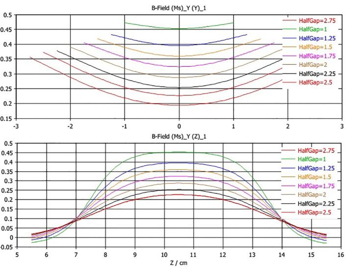
The geometry and materials of the mini-applicator were modeled in finite element software of CST Studio Suite 2015. Simulation began with default value of (1.23 T) for magnetic remanence, Br. By frequent changes in amount of magnetic remanence, the best value for Br was determined to be 1.212T. Figure 4 shows good compliance of results of simulation with values of practical measurements. Results of simulation not only complied well with values inside the applicator, but also, this model precisely predicted the values of the magnetic field outside the applicator. Simulation of the magnetic field was conducted for various distances of the magnet poles. Calculated intensity of the magnetic field as well as the values of measurement in the central point of the field is shown in Figure 5. The highest difference between measurement and simulation values was 2.2% for a distance of 2.5cm between two poles. Curves of magnetic field were extracted along orthogonal directions of calculated matrices which are shown in Figure 6. With regard to the Cerrobend shield located on the mini-applicator, electrons’ path was determined with specified dimensions. Statistical features of the magnetic field in this limited section were also extracted from CST software. Results of Figure 6 and Table 1 show that as the distance between two poles increased, the average intensity of the magnetic field decreased. As the distance between two poles decreased, minimum, maximum and difference between data decreased. In other words, uniformity of the field increased on electrons’ path.
Figure 5.
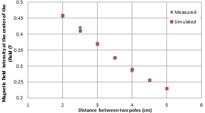
Results of simulated and measured intensities of the magnetic field in the center of the field for different distances between the two poles
Figure 6.
Simulation of magnetic field along orthogonal axes. HalfGap in the curves is half of the distance between the two poles. Z=10.5cm is equivalent to the center of magnetic field.
Table 1.
Calculated features of magnetic field for various distances between two poles
| Distance between two poles (cm) | Maximum magnetic field (T) | Minimum magnetic field (T) | Average magnetic field (T) | Deviation in magnetic field |
|---|---|---|---|---|
| 2.5 | 0.4490 | 0.0493 | 0.3581 | 0.0755 |
| 3 | 0.4372 | 0.0467 | 0.3314 | 0.0742 |
| 3.5 | 0.3888 | 0.1127 | 0.2941 | 0.0656 |
| 4 | 0.3530 | 0.1095 | 0.2577 | 0.0576 |
| 4.5 | 0.3176 | 0.0998 | 0.2257 | 0.0504 |
| 5 | 0.2878 | 0.0924 | 0.2008 | 0.0443 |
| 5.5 | 0.2488 | 0.0822 | 0.1715 | 0.0371 |
3.3. Estimation of Electron’s Path in Magnetic Field
Electron tracking in various intensities of the magnetic field was simulated. Calculated deflection angle of electrons after passing the magnetic field is shown in Table 2. As the distance between two poles increased and the intensity of the magnetic field decreased, the deflection angle of electrons decreased too. 12 MeV electrons deflected more due to having lower kinetic energy. To make electrons perpendicular to the phantom surface, the model was rotated for calculated deflection angle around the accelerator’s isocenter (SSD = 100). The amount of displacement of the beam axis (collision point of the beam to the plane, SSD = 105) was extracted from the simulation results (Table 3). As the distance between the 2 poles increased and intensity of the magnetic field decreased, displacement decreased too.
Table 2.
Electrons deflection angle for intensities of various distances between the 2 poles of the magnet
| Distance between two poles (cm) | Average magnetic field (T) | Deflection angle (degree) | |
|---|---|---|---|
| 15 MeV | 12 MeV | ||
| 2 | 0.4082 | 27.3 | 32.9 |
| 2.5 | 0.3581 | 24.2 | 30.4 |
| 3 | 0.3314 | 21 | 26.5 |
| 3.5 | 0.2941 | 19.1 | 24 |
| 4 | 0.2577 | 17.1 | 21.4 |
| 4.5 | 0.2257 | 15.3 | 19.2 |
| 5 | 0.2008 | 13.9 | 17.4 |
| 5.5 | 0.1715 | 12.1 | 15.2 |
Table 3.
Calculated displacement of the beam’s central axis compared to measured values on the film
| Central axial displacement of the electron beam | Distance between two poles (cm) | ||||
|---|---|---|---|---|---|
| 2 cm | 3 cm | 4 cm | 5 cm | ||
| 15MeV | Calculated at the surface | 5 | 3.95 | 3.24 | 2.64 |
| Measured at the surface | 4.82 | 4.2 | 3.5 | 2.68 | |
| Measured at depth of maximum dose | 4.82 | 4.22 | 3.52 | 2.78 | |
| 12MeV | Calculated at the surface | 6.11 | 4.87 | 4.03 | 3.29 |
| Measured at the surface | 6.04 | 5.12 | 4.33 | 3.32 | |
| Measured at depth of maximum dose | 6.24 | 5.14 | 3.76 | 3.24 | |
3.4. Measuring Electron’s Path in a Magnetic Field Using Exposure to the Film
In various intensities of the magnetic field, the head of the accelerator is rotated for calculated deflection angle (Table 2) to make electrons’ path perpendicular to the water surface again. Exposed films showed displacement of the electron beam axis relative to initial status (initial marked central axis). This displacement was measured on the surface of the film as well as the maximum depth. Table 3 shows measured and calculated displacements using simulations. In most intensities of the magnetic field, values of measured displacement of central axis were very close to calculated values and this confirms the validity of simulation. Difference between simulation and measurement on the film was less than 3 mm. This difference can be due to error in adjusting the center of the field on the sign marked on the film or millimeter displacement of the film in water phantom along × axis (Crossline) while measuring.
4. Discussion
A mini-applicator was designed and manufactured to create a transverse magnetic field on the path of an electron beam of a therapeutic accelerator. This mini-applicator was placed at the end section of a standard applicator without any disturbance in normal function of the accelerator. Intensity of the magnetic field was measured at the center of the field and for various distances between the poles of the magnet. As the distance between poles increased, the intensity of the magnetic field decreased. Point-to-point measurement of the magnetic field showed a complex non-uniformity inside and outside the mini-applicator (Figure 4). This non-uniformity was reported in similar studies (16, 17). Damrongkijidom et al. (18) stated that non-uniformity of the field results in asymmetry of deflected electron beam. Analytical equations were not able to predict the field in all interior and exterior of the space of applicator similar to polynomial equations; therefore, to calculate 3D matrix of the field, a finite element method was used. A model was prepared based on the geometry of mini-applicator and beam source conditions and its validity was confirmed using experimental results (Figure 4). Intensity of the magnetic field was calculated inside and outside of this model. In the similar research, to calculate the magnetic field, other software of finite element method are used (19); however, arrangement and dimensions of the magnet and also its applications have been different. In most studies, tissue was in the magnetic field like designing the MRI-radiotherapy system; therefore, precise calculation of interactions in the tissue was necessary in the presence of the external field. In these studies, for particle tracking inside the tissue under the effect of the magnetic field, some specific Monte Carlo codes are used (20). In our study, the magnetic field was applied only on the electrons’ path before their reaching the phantom surface; therefore, we employed a finite element method to investigate deflection of electrons without being involved in various Monte Carlo processes. The deflection angle of electrons as well as the amount of displacement of impact position of electron beams after accelerator rotation, were calculated (Table 2). Results of measuring by the film confirmed the results of simulating particle tracking using finite element method. Our results complied with results of Damrongkijudom et al. (18) who observed more deflection in low-energy electrons. They predicted deflection of electrons based on theoretical relations, and measured it using film dosimetry. Status and entrance point of electrons to the phantom was estimated and the electron path was appropriately predicted before applying the magnetic field.
5. Conclusions
A useful applicator was manufactured to apply an adjustable transverse magnetic field on and electron beam. This mini-applicator was placed in a standard applicator of linear accelerator easily and safely. Using this tool, the capability of changing the electron beam path and dose distribution in the tissue was provided. To calculate the magnetic field and predict the deflection angle and impact position of the electron beam, a good model was prepared in simulation software using finite element method. By applying the magnetic field and rotating the device head in pre-defined angles, the electron beam was again perpendicular to the phantom surface. Measuring changes in the electron path was conducted using EBT2 GafChromic film. The prepared model showed the ability to simulate and calculate magnetic field and particles’ tracking in complex fields.
Acknowledgments
This article was extracted from a PhD dissertation number U-92086 and it was conducted by financial support of the Research Deputy of Ahvaz Jundishapur University of Medical Sciences. Experts of Medical Physics Department of Ahvaz University of Medical Sciences are appreciated. Experts of Radiotherapy Department of Golestan Hospital in Ahvaz are appreciated for providing an accelerator and their technical device for model validation.
Footnotes
iThenticate screening: August 12, 2016, English editing: January 12, 2017, Quality control: March 15, 2017
Conflict of Interest:
There is no conflict of interest to be declared.
Authors’ contributions:
All authors contributed to this project and article equally. All authors read and approved the final manuscript.
References
- 1.Hogstrom KR, Almond PR. Review of electron beam therapy physics. Phys Med Biol. 2006;51(13):R455–89. doi: 10.1088/0031-9155/51/13/R25. [DOI] [PubMed] [Google Scholar]
- 2.Bostick WH. Possible Techniques in Direct-Electron-Beam Tumor Therapy. Phys Rev. 1950;77(4):564–5. doi: 10.1103/PhysRev.77.564. [DOI] [Google Scholar]
- 3.Whitmire DP, Bernard DL, Peterson MD, Purdy JA. Magnetic enhancement of electron dose distribution in a phantom. Med Phys. 1977;4(2):127–31. doi: 10.1118/1.594309. [DOI] [PubMed] [Google Scholar]
- 4.Becchetti FD. High energy electron beams shaped with applied magnetic fields could provide a competitive and cost-effective alternative to proton and heavy-ion radiotherapy. For the proposition. Med Phys. 2002;29(10):2435–6. doi: 10.1118/1.1510453. [DOI] [PubMed] [Google Scholar]
- 5.Papiez L. Very high energy electromagnetically-scanned electron beams are an attractive alternative to photon IMRT. For the proposition. Med Phys. 2004;31(7):1946–8. doi: 10.1118/1.1760769. [DOI] [PubMed] [Google Scholar]
- 6.Earl MA, Ma L. Depth dose enhancement of electron beams subject to external uniform longitudinal magnetic fields: a Monte Carlo study. Med Phys. 2002;29(4):484–91. doi: 10.1118/1.1461374. [DOI] [PubMed] [Google Scholar]
- 7.Bielajew AF. The effect of strong longitudinal magnetic fields on dose deposition from electron and photon beams. Med Phys. 1993;20(4):1171–9. doi: 10.1118/1.597149. [DOI] [PubMed] [Google Scholar]
- 8.Nardi E, Barnea G, Ma CM. Electron beam therapy with coil-generated magnetic fields. Med Phys. 2004;31(6):1494–503. doi: 10.1118/1.1711477. [DOI] [PubMed] [Google Scholar]
- 9.Wessels BW, Paliwal BR, Parrott MJ, Choi MC. Characterization of Clinac-18 electron-beam energy using a magnetic analysis method. Med Phys. 1979;6(1):45–8. doi: 10.1118/1.594550. [DOI] [PubMed] [Google Scholar]
- 10.Belousov AV, Varzar SM, Chernyaev AP. Simulation of the conditions of photon and electron beam irradiation in magnetic fields for increasing conformity of radiation therapy. Bull Russ Acad Sci Phys. 2007;71(6):841–3. doi: 10.3103/S1062873807060172. [DOI] [Google Scholar]
- 11.Brown D, Ma BM, Chen Z. Developments in the processing and properties of NdFeB-type permanent magnets. J Magn Magn Mater. 2002;248(3):432–40. doi: 10.1016/S0304-8853(02)00334-7. [DOI] [Google Scholar]
- 12.CST STUDIO SUITE. Available from: https://www.cst.com/Products/CSTS2.
- 13.Inc. MSM. Design Guide. Available from: http://www.magnetsales.com/design/designg.htm.
- 14.Maskani R, Tahmasebibirgani MJ, Hoseini-Ghahfarokhi M, Fatahiasl J. Determination of Initial Beam Parameters of Varian 2100 CD Linac for Various Therapeutic Electrons Using PRIMO. Asian Pac J Cancer Prev. 2014;16(17):7795–801. doi: 10.7314/APJCP.2015.16.17.7795. [DOI] [PubMed] [Google Scholar]
- 15.Arjomandy B, Tailor R, Zhao L, Devic S. EBT2 film as a depth-dose measurement tool for radiotherapy beams over a wide range of energies and modalities. Med phys. 2012;39(2):912–21. doi: 10.1118/1.3678989. [DOI] [PubMed] [Google Scholar]
- 16.Damrongkijudom N, Oborn B, Butson M, Rosenfeld A. Measurement of magnetic fields produced by a “Magnetic deflector” for the removal of electron contamination in radiotherapy. Australas Phys Eng Sci Med. 2006;29(4):321–7. doi: 10.1007/BF03178398. [DOI] [PubMed] [Google Scholar]
- 17.Tahmasebi-Birgani MJ, Bayatiani MR, Seif F, Zabihzadeh M, Shahbazian H. Electron Beam Dose Distribution in the Presence of Non-Uniform Magnetic Field. Iran J Med Phys. 2014;11(1):195–204. doi: 10.22038/ijmp.2014.2630. [DOI] [Google Scholar]
- 18.Damrongkijudom N, Oborn B, Butson M, Rosenfeld A. Measurement and production of electron deflection using a sweeping magnetic device in radiotherapy. Australas Phys Eng Sci Med. 2006;29(3):260–6. doi: 10.1007/BF03178575. [DOI] [PubMed] [Google Scholar]
- 19.Keyvanloo A, Burke B, Warkentin B, Tadic T, Rathee S, Kirkby C, et al. Skin dose in longitudinal and transverse linac-MRIs using Monte Carlo and realistic 3D MRI field models. Med phys. 2012;39(10):6509–21. doi: 10.1118/1.4754657. [DOI] [PubMed] [Google Scholar]
- 20.Kirkby C, Stanescu T, Rathee S, Carlone M, Murray B, Fallone BG. Patient dosimetry for hybrid MRI-radiotherapy systems. Med Phys. 2008;35(3):1019–27. doi: 10.1118/1.2839104. [DOI] [PubMed] [Google Scholar]


