Abstract.
Acoustic neuroma surgery is a procedure in which a benign mass is removed from the internal auditory canal (IAC). Currently, this surgical procedure requires manual drilling of the temporal bone followed by exposure and removal of the acoustic neuroma. This procedure is physically and mentally taxing to the surgeon. Our group is working on the development of an acoustic neuroma surgery robot (ANSR) to perform the initial drilling procedure. Planning the ANSR’s drilling region using preoperative CT requires expertise and takes about 35 min. We propose an approach for automatically producing a resection plan for the ANSR that would avoid damage to sensitive ear structures and require minimal editing by the surgeon. We first compute an atlas-based segmentation of the mastoid section of the temporal bone, refine it based on the position of anatomical landmarks, and apply a safety margin to the result to produce the automatic resection plan. In experiments with CTs from nine subjects, our automated process resulted in a resection plan that was verified to be safe in every case. Approximately 2 min were required in each case for the surgeon to verify and edit the plan to permit functional access to the IAC. We measured a mean Dice coefficient of 0.99 and surface error of 0.08 mm between the final and automatically proposed plans. These preliminary results indicate that our approach is a viable method for resection planning for the ANSR and drastically reduces the surgeon’s planning effort.
Keywords: acoustic neuroma, atlas-based segmentation, internal auditory canal, cochlea, facial nerve
1. Introduction
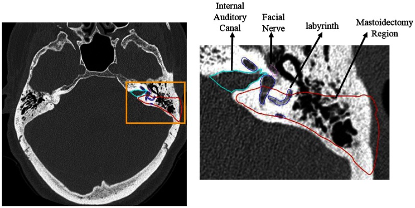
An acoustic neuroma, which is a widely used misnomer for vestibular schwannoma because the tumor is not derived from neurons of the acoustic nerve but rather the Schwann cells of the vestibular nerve, is a benign tumor originating from the vestibular nerve. Surgical treatment for acoustic neuroma involves opening the internal auditory canal (IAC) to access the tumor and dissecting it from the facial nerve and brainstem. The IAC is a canal located in the temporal bone that serves as the passageway for cranial nerves and is the location where acoustic neuromas form. The location of the IAC is shown in Fig. 1 in light blue.
Fig. 1.
IAC where acoustic neuromas form is shown in light blue outline, and the region removed during 48 the mastoidectomy is shown in red outline. The sensitive inner ear structures are also shown with the facial nerve depicted in 49 pink and the cochlear labyrinth depicted in dark blue.
Although benign, as this mass grows it can begin to press against the cochlear nerve that controls hearing, the vestibular nerves that control balance, and the facial nerve that controls facial expression, causing loss of hearing, ear ringing, dizziness, balance problems, and sometimes facial weakness. The most common presentation is unilateral hearing loss with or without tinnitus and unsteadiness. Approximately one-third of individuals have nonaidable hearing at presentation.1 After diagnosis by MRI, 28% of patients are observed with repeat MRI, 24% treated with radiation therapy, and 48% undergo surgical resection2 via one of three surgical approaches: the translabyrinthine approach, the retrosigmoid approach, or the middle cranial fossa approach. Given (a) the high incidence of nonserviceable hearing at presentation and the natural history of continued hearing loss1 and (b) the wide surgical exposure without the need to retract the brain, the most commonly used is the translabyrinthine approach, which sacrifices residual hearing.3 In this approach, a mastoidectomy followed by labyrinthectomy is performed to obtain access to the exterior bony wall of the IAC as shown in Fig. 1. During mastoidectomy, the mastoid region of the temporal bone is drilled away, and during labyrinthectomy, the semicircular canals of the cochlear labyrinth are resected. After access to the exterior bony wall of the IAC is achieved, the bone is thinned until transparent so that it can be removed gently and safely in order to open the IAC and remove the tumor. The translabyrinthine approach puts several demands on the surgeon. The initial drilling step (mastoidectomy and labyrinthectomy) is physically taxing and can take 2 to 3 h. In addition, the surgeon must be very precise during this portion of the procedure in order to identify and avoid damage to a number of sensitive anatomical structures that lie along the surgical path. The next step is also challenging. It is completed after the mastoidectomy when only a thin layer of bone is left covering the IAC. The surgeon must meticulously pick the thin bone away in order to gain access to the IAC. The initial drilling steps increase the likelihood of mental mistakes in the final portion of the procedure in which the acoustic neuroma is removed, which, depending on the patient’s anatomy, can require a high degree of precision.
Our group is working toward the development of an acoustic neuroma surgery robot (ANSR) to perform the initial drilling procedure to gain access to the IAC. Future cadaveric studies may show that the ANSR is able to provide safe access to the IAC. If safe, the ANSR could greatly benefit the surgeon by decreasing the amount of physical and mental effort expended prior to the acoustic neuroma identification and removal step. This robot may directly benefit patients as well by decreasing the total procedure time, and thus time under anesthesia, while maintaining the same level of safety and efficacy as the traditional approach. In order for a robot to perform this drilling procedure, its path must be planned using preoperative CT images. This path must drill through the mastoid region and reach the IAC while avoiding vital structures such as the facial nerve. Once the region to be resected is defined, a complete set of instructions for the robot can be determined using drill path planning techniques that have previously been developed.4 Currently, the drilling path utilized by the ANSR is manually delineated by the surgeon using custom-developed image segmentation software. As will be shown in our results section, manual delineation is prohibitively time consuming, typically requiring around 35 min of work. In the experience of the authors (GW and RFL), it also requires great care and expertise. In this work, we seek to develop an automatic approach for delineating the resection region using CT images.
The task of automatically delineating the resection region falls within the field of medical image segmentation. Segmentation techniques fall broadly into two classes, pixel classification-based and boundary-based techniques. Pixel classification techniques include techniques such as thresholding-based5 and machine learning-based6,7 techniques that aim to label individual pixels. In contrast, boundary-based methods aim to localize the boundary of the structure of interest. Such methods include level sets,8 active shape models,9 snakes,10 graph cuts,11 and atlas-based methods, in which manually labeled images, or “atlases,” are used to automatically label new target images by computing a nonrigid registration transformation that registers the atlas image to the target image.12,13 Then the labels that are defined on the atlas are mapped to the target image using the registration transformations. More complete reviews of image segmentation methods are available in the literature.14,15 Delineating a resection region requires a boundary-based segmentation approach because it is important that the resection region be of a simple topology (i.e., one connected component) and be generally convex in shape to permit drilling, and these types of shape constraints are difficult to implement with pixel classification techniques. A subset of boundary-based approaches, such as level sets, snakes, and graph-based techniques, also makes this type of shape constraint difficult to enforce. Furthermore, these methods also require globally discriminant features, such as image edges corresponding to a tissue interface, to be present over the vast majority of the region boundary. This is an issue for our application because the borders of the mastoidectomy region lie within the temporal bone and do not correspond to a specific tissue interface. Active shape models are robust to these issues but require a training set large enough to capture population shape variance. Thus, we propose an atlas-based segmentation technique using nonrigid registration because such techniques are robust to these issues. They also have the advantage of providing a normalized anatomical coordinate system, via registration with a known atlas image, that can be used to enforce spatially varying shape constraints on the segmentation, as will be presented below. Our proposed method is a multistep approach in which we first compute an atlas-based segmentation of the mastoid section of the temporal bone, refine it using anatomical landmarks, and finally apply a safety margin to the result, producing a resection plan that requires only minimal editing by the surgeon. Automatic delineation of the resection region could lower the learning curve for surgeons who wish to adopt the ANSR approach and lead to more consistent plans across surgeons and patients.
2. Methods
Atlas-based segmentation is an approach in which manually labeled images, or atlases, are used to automatically label new target images. In this approach, one or more transformations are computed that register the atlas image to the target image. Then the labels that are defined on the atlas are mapped to the target image using the registration transformations. Prior work from our group has shown that atlas-based segmentation techniques can be used to accurately localize certain structures of the ear that have consistent topology and appearance across different subjects.16 However, the same techniques are not directly applicable to localization of the resection volume of the ANSR. This is because the borders of the mastoidectomy lie within the temporal bone, which has a pneumatization pattern that is highly variable. It is well known that atlas-based segmentation techniques are sensitive to such topological differences. This sensitivity makes atlas-based segmentation techniques inadequate when used alone.
To account for these issues while still exploiting the atlas-based approach that was validated in prior studies, a multistep atlas and landmark-based segmentation approach was developed. The first step is to segment the boundaries of the mastoid region of the temporal bone using atlas-based techniques16 to serve as a coarse unedited segmentation of the resection region. The atlas-based approach relies on a sequence of linear and nonlinear registrations computed between the target and an atlas image to automatically map a segmentation of the mastoid that was manually created in the atlas image to the target image volume. Typically, with an atlas-based approach, the borders of the segmentation in the atlas image are defined to match the structure-of-interest (SOI), the planned region of resection in this application, as closely as possible. Our SOI has borders that fall within the pneumatized bone of the mastoid as shown in Fig. 2 in blue. As mentioned previously, this poses a problem as registration in this area is often inaccurate due to intersubject variability. To account for this, the initial segmentation volume in the atlas image is extended to follow the contours of the skull rather than the SOI itself as shown by the red contour in Fig. 2. The exterior borders of the red contour are well identified in the target image via an atlas-based approach.
Fig. 2.
Comparison between surgeon’s manually delineated resection plan (blue) and the segmentation of the full mastoid region of the temporal bone (red) that is used in our atlas-based segmentation step.
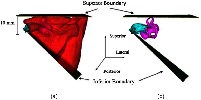
The next step is to refine the borders of the initial segmentation using a landmark-based strategy based on the decisions the surgeon typically makes during surgery. This first requires segmenting the IAC, labyrinth, and facial nerve to serve as landmarks. The IAC and the labyrinth are localized using atlas-based techniques16 and the facial nerve is localized using techniques we have previously developed and validated.17 To refine the superior boundary of the SOI, the SOI is edited so that no tissue is resected superior to the labyrinth. The superior boundary can be defined as a simple axially oriented plane, while the inferior boundary must be defined as a slanted plane (see Fig. 3). This permits the inferior boundary of the IAC to be reached while also allowing the SOI to expand inferiorly away from the IAC as it approaches the lateral surface of the skull. This constraint permits adequate access for surgical tools necessary for the removal of the acoustic neuroma. To implement this constraint, a plane is defined that contains the most inferior point on the IAC segmentation and two points on the mastoid tip. The SOI is then automatically updated so that no tissue is resected inferior to this plane.
Fig. 3.
The superior and inferior resection boundaries shown (a) with the automated resection surface included and (b) with the automated resection surface removed. The IAC is shown in cyan, the labyrinth is shown in magenta, and the automated resection surface is shown in red.
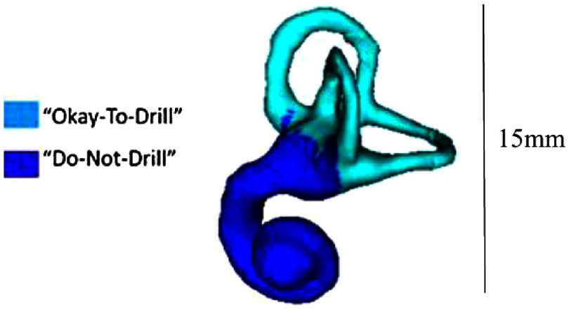
Next, the anterior boundary of the SOI is updated to ensure the anterior border of the IAC can be reached while remaining posterior to the facial nerve and the portion of the labyrinth that cannot be resected. As mentioned previously, the semicircular canals of the labyrinth are removed during the manual drilling portion of the surgery. While their removal is unavoidable, it is preferred to remove only portions of the labyrinth needed to gain access to the IAC. In order to define which portions of the labyrinth cannot be drilled, the vertices of the labyrinth that are allowed to be drilled versus those vertices that cannot be drilled are labeled in the atlas labyrinth surface based on the surgeon’s recommendations. The labyrinth surface is segmented in the target image using an atlas-based technique that results in a one-to-one point correspondence between the atlas and target surface vertices. Automatically defining the vertices in the target labyrinth that should not be drilled is done by simply using the same labels defined in the atlas. Figure 4 shows the two labels as defined by the surgeon.
Fig. 4.
Labyrinth labels designating the portion of the labyrinth that should and should not be drilled based on the surgeon’s recommendations.
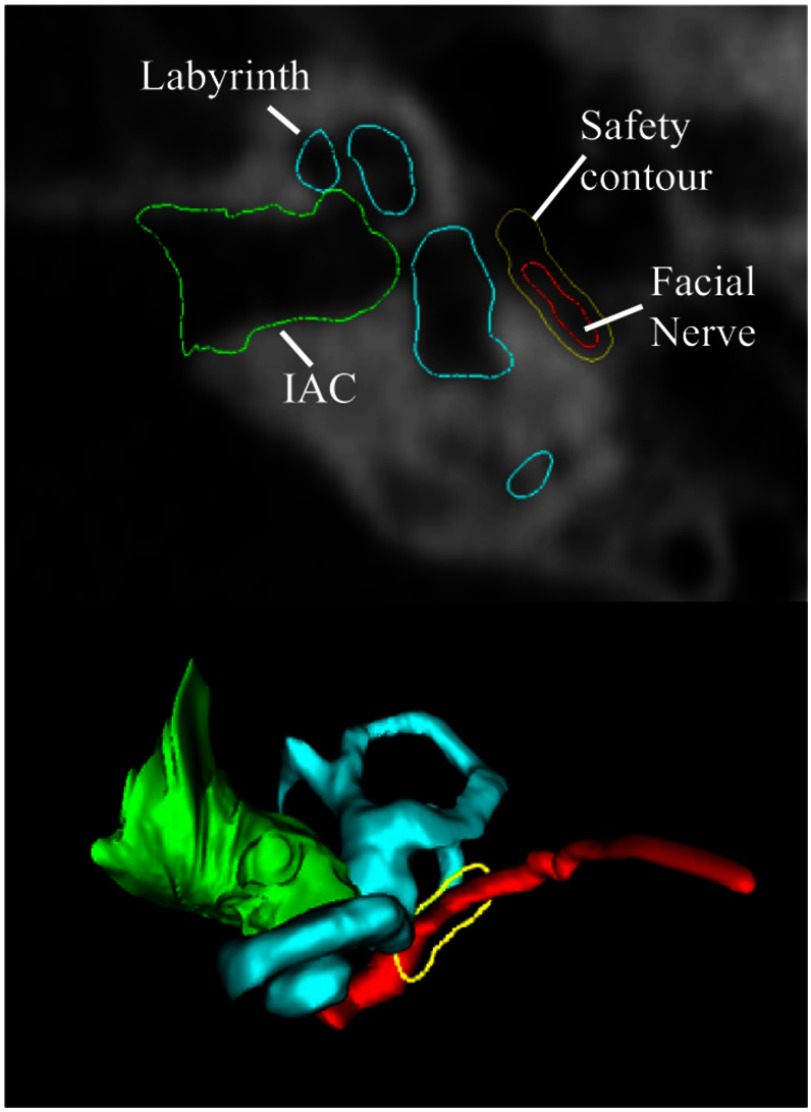
To define a 0.5-mm safety margin of bone around the facial nerve that cannot be drilled, a three-dimensional (3-D) distance map is computed for the facial nerve. In each axial slice, isocontours are computed from the distance map 0.5 mm from the facial nerve. An example slice of this contour as well as its 3-D representation is shown in Fig. 5.
Fig. 5.
Example of the 0.5-mm safety contour (shown in yellow) around the facial nerve (shown in red). The labyrinth is shown in light blue and the IAC is shown in green. The top figure shows an axial CT slice, and the bottom shows the 3-D surfaces with the safety contour corresponding to the axial slice.
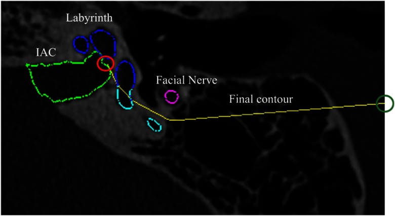
Due to the complex spatial relationship of these structures, updating the anterior boundary of the SOI to ensure it does not violate the facial nerve safety margin or the portion of the labyrinth that cannot be resected cannot be done using edits defined by simple planar geometry. We thus define a decision contour in each axial plane and automatically adjust the SOI so that no tissue is resected anterior to the decision contour in that axial plane. The contour (an example is shown in yellow in Fig. 6) is defined as the shortest convex path that connects the most anterior point of the IAC, , to the most posterior point on the facial nerve safety margin isocontour, , and passes posterior to both the facial nerve isocontour and the portions of the labyrinth that cannot be resected. The algorithm for determining the contour path, , is shown in Algorithm 1.
Fig. 6.
Example of final contour (shown in yellow) for one axial slice. The IAC is shown in light green, the facial nerve is shown in pink, and the labeled labyrinth is shown in dark blue and light blue. The initial point on the IAC is indicated by the red circle. The end point is indicated by the dark green circle.
Algorithm 1.
Algorithm to compute convex contour .
| , |
| while |
| end-while |
The algorithm starts by initializing a temporary variable to be equal to and the path to contain . Within the while loop, is a set that contains two sets of points: (1) the points that compose the portion of the labyrinth surface that cannot be resected and that fall within the specific axial slice of interest and (2) the points that compose the facial nerve safety margin isocontour for that axial slice. We aim to find a contour to serve as a border to the drilling region that is not anterior to any of the points in , and is convex so that drilling into concavities is not required. This is related to the problem of finding the convex hull of a set of points,18 but can be simplified here as we do not need a complete convex hull but rather aim to find a convex path around a set of points. Each iteration of the while loop updates to be the next point along the contour path that is added to the convex contour . The first two lines in the while loop are used to find the point in such that a line segment formed by connecting the current path endpoint to that point would have the largest angle in the posterior direction relative to the vector . That is then chosen as the next point added to the contour path. Choosing the next point to add to the contour path in this way guarantees that the resulting path is convex and passes posterior to all . The while loop terminates when the final point added to the contour path is equal to , the most posterior point on the facial nerve safety margin isocontour. Once the contour reaches the most posterior point on the facial nerve isocontour, it is extended laterally to the surface of the skull. The steps of this algorithm are visualized in Fig. 7. In the figure, , , , and are defined as in Algorithm 1. In the first step, the vector is found to be the one that makes the largest posterior angle relative to and therefore is chosen as the next step in the contour path. Similarly, is found to do the same in iteration 2. In the third iteration, this is found to be the case for , thus completing the process of finding a convex path from to that does not pass anterior to any . This process of finding decision contours is completed in each axial slice. Taken together, the decision contours form a 3-D decision surface. A common issue when analysis is performed slice-by-slice in this fashion is that it produces an irregular 3-D shape. However, this issue is avoided here because the contours are constructed based on smooth 3-D landmarks. The posterior border of the SOI does not need to be refined as it is well-defined already by the border of the skull-brain interface.
Fig. 7.
Visualization of the contour path finding algorithm. In each iteration, the contour path is grown to the point in that makes the widest angle relative to . The algorithm terminates when the end point is reached.
Finally, to account for the fact that surgeons typically desire a 1-mm margin of bony tissue to not be drilled at the borders of the resection region and to account for up to 1 mm of error in the drilling system, we apply an erosion to the SOI. A simple global erosion using a spherical structuring element (SE) in this case is not desirable as the lateral wall of the SOI on the mastoid is where the ANSR will begin drilling and must not be eroded. Instead, a spatially adaptive structuring element (SASE) is used. The SASE must be a full sphere for most of the SOI to ensure safety but should be a medial-facing quarter-sphere at the lateral edge of the SOI to prevent eroding the border of the SOI at the lateral surface of the skull.
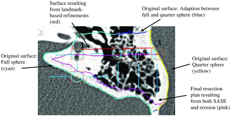
Rather than defining the SASE to sharply transition from full to partial sphere, the SASE is designed to vary smoothly over the image space so that the final resection plan will be smooth. The spatial adaptation function, i.e., the function that defines the shape of the SASE based on spatial location, cannot be defined using simple planar geometry due to the contoured shape of the skull. Instead, the spatial adaptation function is defined using a radial basis function network approach. To do this, first, a surface defined around the initial segmentation volume in the atlas image is projected onto the target image through the compound registration transformation. Figure 8 shows an axial slice of a target image with the cut of the axial slice through this surface shown as the blue, cyan, and yellow contour. Each vertex in the original surface in the atlas image is classified into one of three groups: vertices in a region that requires a full spherical SE (cyan), those in a region that requires a quarter spherical SE (yellow), and those that fall between these two regions (blue). These vertex classifications are then identically mapped to the corresponding vertices in the target surface. The colors of the contour in Fig. 8 show an example result of this process. Next, a Gaussian radial basis function is defined in the target image at the location of each ’th surface vertex in the group of vertices classified in the cyan or yellow groups. Finally, the spatial adaptation function can be defined using the network of radial basis functions as
| (1) |
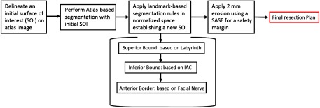
where is selected to be 2 mm, represents the fraction of the sphere of the SE associated with , and is equal to 1 for the cyan group and 0.25 for the yellow group, and defines the fraction of the sphere that we select to be used for the SE at location in the target image. In summary, the shape of the SE is defined by Eq. (1) as a weighted average of the SE shape defined at sites around the initial segmentation surface, where weights are selected based on the distance to each site. Medially, the SE is a full sphere as shown in “1” in Fig. 8. Further laterally over the mastoid, in region “2,” the SE sphere becomes a fraction of a sphere. Finally, at the lateral edge of the mastoid, region “3,” the SE is its smallest at a quarter of a sphere. The SOI volume that has been refined using the landmark-based scheme described above (shown as red contour in Fig. 8) is eroded using the SASE with a radius of 2 mm (shown as cyan SEs in the figure) to add a safety margin and account for targeting error, resulting in a final automatic resection volume (shown as magenta contour in the figure). Note that while the spatial adaptation function in Eq. (1) is defined based on the initial segmentation surface (multicolored contour), it is a 3-D function and thus can be used to apply the SASE to erode the refined (red contour) rather than the initial segmentation. A summary of the combined steps for the multistep atlas and landmark-based segmentation approach described is shown in Fig. 9.
Fig. 8.
The SASE process. Light blue circles show the SE that is being used for the voxel of interest (orange x). The dashed orange box surrounding the SE shows the range of the SE. The initial mastoid segmentation surface is shown in cyan, blue, and yellow. The resection plan prior to erosion is shown in red (most of the red contour is occluded by the cyan, blue, and yellow contour) and the resulting resection plan after erosion is shown in magenta.
Fig. 9.
Flowchart summarizing the multistep atlas and landmark-based segmentation approach discussed in the methods section.
To validate the safety of the automatic resection plan, first, the surgeon manually delineated a maximum safe drilling volume from scratch for each patient, without benefit of the automatic resection plan. This required 35 min from the surgeon per patient on average. Then, the percentage of voxels of the automatic resection plan located inside the manually defined maximum drilling volume was calculated. Some difficulty was encountered in defining a truly maximum drilling volume due to differences between the region that is typically drilled in surgery and additional regions that may not always be resected but are still safe to drill. In addition, there are some difficulties in precisely defining a 3-D volume by manually delineating a sequence of two-dimensional slices. To account for this, any voxels in the automatic plan that were located outside the maximum drilling region were then examined by the surgeon and further labeled as safe or unsafe. To verify that the automatic resection plan is functional, the surgeon was instructed to make any adjustments to the automatic resection plan that would be required so that when the ANSR finishes the drilling, the surgeon would need only to thin the bone around the IAC to reach the acoustic neuroma and would be provided adequate working space to do so. The adjusted plan was then compared to the automatic plan using surface distance measurements and Dice similarity coefficient (DSC).19
3. Results
The segmentation procedure described above was performed on nine separate patient CT scans: five patients and four cadavers. Results are shown in Table 1. A mean of 96% of resection plan voxels was found to be within the maximum region. Notice that the lower amount of voxels found within the maximum region is for the cadaver images (6 to 9).
Table 1.
Quantitative validation results for automatic resection plans.
| Patient | 1 | 2 | 3 | 4 | 5 | 6 | 7 | 8 | 9 | Mean | Worst case |
|---|---|---|---|---|---|---|---|---|---|---|---|
| % Within maximum | 99.07 | 95.46 | 98.79 | 99.06 | 97.92 | 92.98 | 90.96 | 93.57 | 98.61 | 96.27 | 90.96 |
| Verified safe | Yes | Yes | Yes | Yes | Yes | Yes | Yes | Yes | Yes | N/A | Yes |
| Max surface error (mm) | 1.88 | 1.96 | 2.74 | 4.98 | 3.84 | 1.73 | 2.63 | 3.11 | 1.29 | 2.69 | 4.98 |
| Mean surface error (mm) | 0.04 | 0.05 | 0.09 | 0.09 | 0.17 | 0.09 | 0.06 | 0.1 | 0.06 | 0.08 | 0.17 |
| Dice coefficient | 0.99 | 0.99 | 0.99 | 0.99 | 0.97 | 0.99 | 0.99 | 0.97 | 0.99 | 0.99 | 0.97 |
| Time to edit automatic plan (min) | 3:00 | 1:48 | 3:00 | 2:19 | 6:02 | 1:58 | 2:15 | 2:38 | 2:08 | 2:08 | 6:02 |
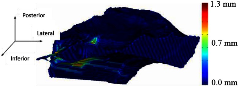
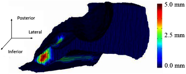
This most likely is caused by the fact that the cadaver images were acquired with a cone beam scanner that has lower signal-to-noise ratio compared to the clinical scans acquired for the patients, which made it more difficult to manually identify a maximum region and to generate an automatic resection plan due to a decrease in registration accuracy. The few voxels that were located outside the maximum for each patient were examined, and these were verified by the surgeon as voxels that could still be safely drilled. Good agreement is seen between the automatic and adjusted surfaces with small mean and maximum surface errors of 0.08 and 2.69 mm, respectively, and a high average DSC of 0.99 on average. 3-D renderings of two of our resulting surfaces that correspond to the surface with the smallest max surface error and the largest max surface error (cases 9 and 4) are shown in Figs. 10 and 11, respectively. In the figures, the automatically generated resection plans are color-mapped with distance to the border of the adjusted plan. The highest errors occur medially or around the IAC, indicating that our plan was conservative in this region.
Fig. 10.
Resection plan for the best case color-mapped with error distance.
Fig. 11.
Resection plan for worst case color-mapped with error distance.
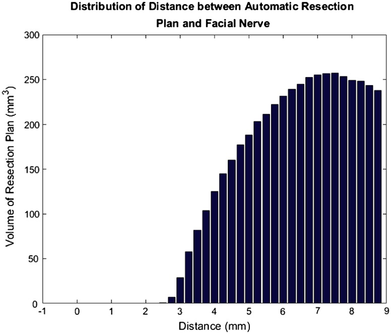
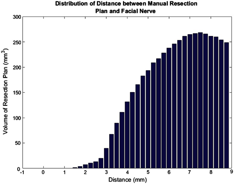
In addition, we examined the distances from the facial nerve for all subjects for both the final automated resection plan (Fig. 12) and the manual resection plan (Fig. 13). The plots show the distribution of total volume to be resected across all cases as a function of distance to the facial nerve for the automatic and manual resection plans, respectively. Only distances up to 9 mm were included as the closest distances are the most relevant. These plots also show good agreement among the plans. However, the manual resection plan approaches 1 mm distance from the facial nerve while the automated plan has a minimum distance of 2.5 mm. This shows again that our automated resection plan is overly conservative and prioritizes the safety of the facial nerve.
Fig. 12.
Bar plot of total automatic resection plan volume as a function of the distance to the facial nerve.
Fig. 13.
Bar plot of total manual resection plan volume as a function of the distance to the facial nerve.
4. Conclusions
In this study, we present the first approach for automatically determining patient-specific resection plans for acoustic neuroma surgery. Another group has developed techniques for segmentation of the exterior borders of the mastoid bone.20 The exterior borders of the mastoid are defined by a smooth bony surface with consistent topology, thus it lends itself well to an atlas-based segmentation approach alone. Our problem is distinct in that we need to identify a drilling region within the mastoid bone. The border of our drilling region lies where there exists pneumatized bone, which has unpredictable topology across individuals, thus requiring a unique combined atlas-based segmentation and landmark-based approach. Our approach could be beneficial in other applications aimed at segmenting tissue for resection with spatially varying constraints on the resection volume, or in other general segmentation applications in which some borders of the region of interest are well defined by image information while others are definable only by their spatial relationship with other structures and are not easily localizable with standard segmentation techniques.
Our approach was verified to be safe in every case. In all cases, the surgeon edited the resection plan to move its border closer to the IAC. At this time, it is not possible to perform the same edits automatically and still conform to the safety margin criteria we have defined. However, editing the automatic plan required an average of only 2 min of work by the surgeon, which represents a drastic reduction in required effort compared to manual planning, requiring an average of 35 min. In all instances where edits were made, the surgeon was increasing the drilling volume. This shows that our plan was generally conservative rather than unsafe, which is preferred. While this preliminary study is relatively small (), it demonstrates the promise of our proposed method. In future work, we will evaluate our approach on a larger dataset to confirm our findings.
Acknowledgments
This research has been supported in part by grant R01DC012593 from the National Institute on Deafness and Other Communication Disorders. The content is solely the responsibility of the authors and does not necessarily represent the official views of this institute.
Biography
Biographies for the authors are not available.
Disclosures
Dr. Robert Labadie is a consultant for Advanced Bionics, Cochlear Americas, and Ototronix. Dr. George Wanna is on the surgical advisory board for Oticon Medical and is a consultant for AB, Cochlear, and MED-EL. No conflicts of interest were reported by the other authors.
References
- 1.Stangerup S. E., et al. , “Hearing outcomes of vestibular schwannoma patients managed with ‘wait and scan’: predictive value of hearing level at diagnosis,” J. Laryngol. Otol. 124(5), 490–494 (2010). 10.1017/S0022215109992611 [DOI] [PubMed] [Google Scholar]
- 2.Carlson M. L., et al. , “The changing landscape of vestibular schwannoma management in the United States: a shift toward conservatism,” Otolaryngol.–Head Neck Surg. 153(3), 440–446 (2015). 10.1177/0194599815590105 [DOI] [PubMed] [Google Scholar]
- 3.Propp J. M., et al. , “Descriptive epidemiology of vestibular schwannomas,” Neuro-Oncology 8, 1–11 (2006). 10.1215/S1522851704001097 [DOI] [PMC free article] [PubMed] [Google Scholar]
- 4.Dillon N. P., et al. , “Preliminary testing of a compact, bone-attached robot for otologic surgery,” Proc. SPIE 9036, 903614 (2014). 10.1117/12.2043875 [DOI] [PMC free article] [PubMed] [Google Scholar]
- 5.Otsu N., “A threshold selection method from gray-level histograms,” IEEE Trans. Syst., Man, Cybern. 9(1), 62–66 (1979). 10.1109/TSMC.1979.4310076 [DOI] [Google Scholar]
- 6.Cortes C., Vapnik V., “Support-vector networks,” Mach. Learn. 20(3), 273–297 (1995). 10.1007/BF00994018 [DOI] [Google Scholar]
- 7.Krizhevsky A., Sutskever I., Hinton G. E., “Imagenet classification with deep convolutional neural networks” in Advances in Neural Information Processing Systems, pp. 1097–1105 (2012). [Google Scholar]
- 8.Sethian J. A., Level Set Methods and Fast Marching Methods: Evolving Interfaces in Computational Geometry, Fluid Mechanics, Computer Vision, and Materials Science, Cambridge University Press, Cambridge, United Kingdom: (1999). [Google Scholar]
- 9.Cootes T.F., et al. , “Active shape models—their training and application,” Comput. Vision Image Understanding 61, 38–59 (1995). 10.1006/cviu.1995.1004 [DOI] [Google Scholar]
- 10.Kass M., Witkin A., Terzopoulos D., “Snakes: active contour models,” Int. J. Comput. Vision 1(4), 321–331 (1988). 10.1007/BF00133570 [DOI] [Google Scholar]
- 11.Boykov Y., Veksler O., Zabih R., “Fast approximate energy minimisation via graph cuts,” IEEE Trans. Pattern Anal. Mach. Intell. 23, 1222–1239 (2001). 10.1109/34.969114 [DOI] [Google Scholar]
- 12.Rueckert D. L., et al. , “Nonrigid registration using free-form deformations: application to breast MR images,” IEEE Trans. Med. Imaging 18(8), 712–721 (1999). 10.1109/42.796284 [DOI] [PubMed] [Google Scholar]
- 13.Roahde G. K., Aldroubi A., Dawant B. M., “The adaptive bases algorithm for intensity-based nonrigid image registration,” IEEE Trans. Med. Imaging 22(11), 1470–1479 (2003). 10.1109/TMI.2003.819299 [DOI] [PubMed] [Google Scholar]
- 14.Sonka M., Hlavac V., Boyle R., Image Processing, Analysis and Machine Vision, Thomson Learning, Singapore: (1999). [Google Scholar]
- 15.Pham D. L., Xu C., Prince J. L., “Current methods in medical image segmentation,” Annu. Rev. Biomed. Eng. 2, 315–337 (2000). 10.1146/annurev.bioeng.2.1.315 [DOI] [PubMed] [Google Scholar]
- 16.Dillon N. P., et al. , “Preliminary testing of a compact, bone-attached robot for otologic surgery,” Proc. SPIE 9036, 903614 (2014). 10.1117/12.2043875 [DOI] [PMC free article] [PubMed] [Google Scholar]
- 17.Noble J. H., et al. , “Automatic identification and 3D rendering of temporal bone anatomy,” Otol. Neurotol. 30(4), 436–442 (2009). 10.1097/MAO.0b013e31819e61ed [DOI] [PMC free article] [PubMed] [Google Scholar]
- 18.Graham R. L., “An efficient algorithm for determining the convex hull of a finite planar set,” Inf. Process. Lett. 1, 132–133 (1972). 10.1016/0020-0190(72)90045-2 [DOI] [Google Scholar]
- 19.Dice L. R., “Measures of the amount of ecologic association between species,” Ecology 26, 297–302 (1945). 10.2307/1932409 [DOI] [Google Scholar]
- 20.Tolsdorff B., et al. , “Individual models for virtual bone drilling in mastoid surgery,” Comput. Aided Surg. 14(1–3), 21–27 (2009). 10.3109/10929080903040540 [DOI] [PubMed] [Google Scholar]


