

Abstract
Background:
Ultrasonography can show local and superficial fractures of the nasal bone. However, it is difficult to see the whole nasal bone. We used water as the coupling medium for ultrasonography.
Methods:
This method was used in 76 nasal bone fracture cases from July 2011 to March 2013, and we could obtain clear images of the entire nasal bone and surrounding bones. However, in some images, there were artifacts and blurred areas. The patterns of blurring were classified and their causes were analyzed.
Results:
The 6 patterns of artifacts and blurred images were (1) Blurred side wall of the nasal bone in 68 cases, (2) air bubbles in the water in 68 cases, (3) unclear deep portions by attenuation in 23 cases, (4) distorted images caused by shaking of the probe in 44 cases, (5) parallel shadows due to multiple reflections in 18 cases, and (6) mysterious shadows caused by side lobes of the ultrasound beams in 55 cases. Almost all of them could be avoided by adding some small changes of techniques.
Conclusions:
Our methods can provide whole clear images of the nasal bone and surrounding bones in 1 field. Almost all the artifacts and blurred images which occurred during the performance of our methods could be avoided by adding some small changes, for example, tilting the probe, pouring the water slowly, and moving the probe closer to the nose.
INTRODUCTION
For the diagnosis of facial bone fractures, ultrasonography has been reported to be reliable.1–4 Ultrasound is a noninvasive imaging technique without risk of radiation exposure. Ultrasonography can be used as an accurate technique for evaluating nasal bone fractures, and it can replace conventional radiography.5 It is more accurate than computed tomography (CT) in nasal fractures.6,7 In children, sonography can be a primary diagnostic technique for evaluating nasal fracture without radiation, and it provides various imaging planes without change of position.8 The use of ultrasonography-assisted closed reduction has been reported in the treatment of nasal bone fracture.9,10 Ultrasonography can demonstrate local and superficial fractures of the nasal bone.
However, it is difficult to see the whole nasal bone and the neighboring facial bones because the probe cannot be applied to the complicated three-dimensional structure of the nose. Various media are used to solve the problem.11,12 We used saline as the coupling medium for ultrasonography in nasal bone fracture.13 Clear whole images of the nasal bone could be obtained because the attenuation index of water is the lowest among the various media (Table 1), and the absorption of ultrasound signals is lowest. Because it is not necessary for the probe to contact the nose, we can use the probe safely even after reduction of the nasal fracture. And water conforms to the contours of the nose perfectly, leaving no gaps.
Table 1.
Attenuation Index of Various Media

Our methods have been used in many patients, but in some cases, the images were unsatisfactory for the diagnosis and evaluation of reduction in nasal bone fractures. To refine and establish this new method, we examined many images, classified them as clear or artifact and blurred image, and analyzed the causes of artifacts and blurring. The purpose of this study was to decide the best way to obtain the clearest image in ultrasonography of nasal bone fractures using water as the coupling medium.
PATIENTS AND METHODS
Ultrasonography with the use of water as coupling medium was performed in 76 patients with nasal bone fracture diagnosed by CT at Chikamori Hospital from July 2011 to March 2013 and at Osaka Medical College from April 2013 to December 2015 (Table 2). The average age of the 49 men and 27 women was 30 years, ranging from 6 to 78 years. In 54 patients, the diagnosis was crooked nose, in 4 it was saddle nose, and in 18 a combination of the two. A Venue 40 or 50 of the echo device (GE Healthcare, Wuxi City, China) and a 12 MHz linear array probe were used under general anesthesia. To keep saline on the face, the outer frame of a snorkeling mask made of thermoplastic elastomer was first used. To prevent saline from entering the nasal cavity, the nostrils were sealed with medical tape. Recently, the outer frame was replaced by a plastic container whose bottom edge was attached to a sponge and wrapped with a waterproof seal (Fig. 1). The sponge could close the nostrils. An ultrasound probe could be applied through the pool of saline without adding pressure to the nasal bone fracture site. Ultrasonographic images in the 4 different directions (axis, sagittal, inclining views from the right and left) were scanned routinely before and after reduction (Fig. 2).
Table 2.
Our Cases by Using Water as a Coupling Medium

Fig. 1.

The apparatus for ultrasonography with water as the coupling medium. A, A plastic container with a sponge attached to its bottom. A waterproof seal wraps them. The sponge can close the nostrils. B, The ultrasound probe can be applied through the pool of saline without adding pressure to the nasal bone fracture.
Fig. 2.

Ultrasound images, with saline used as a coupling medium, of a 16-year-old boy who had a nasal bone fracture. A, Axial view. B, Sagittal view.
The ethical committees in Chikamori Hospital and Osaka Medical College had approved these methods. Printed papers of the ultrasonographic images obtained by using these methods were examined for blurred images, and the blurred patterns were classified. During scanning ultrasonography, we tried to correct the artifacts and blurring by refining our method.
Regarding the statistical analysis, several papers have already reported the diagnostic sensitivity and utility of ultrasonography in the diagnosis of nasal bone fractures in comparison with ultrasonography, radiograph, and/or CT 1,5-7. In this analysis, the results of CT were evaluated as true positive (TP) or true negative (TN) states. Sensitivity and specificity were calculated using the common formula as follows, respectively,: sensitivity = TP/[TP + false-negative (FN) results] and specificity = TN/[TN + false-positive (FP)]. Positive predictive values (PPVs) and negative predictive values (NPVs) were calculated using TP/(TP + FP) and TN/(TN + FN).
RESULTS
The artifacts and blurred images were classified into 6 groups of patterns (Fig. 3).
Fig. 3.

Six kinds of blurred image patterns seen during this study.
1) Blurred side wall of the nasal bone. Especially in the axial view, part of the side wall of the nasal bone became blurred in 68 of 76 cases (Table 3).
Table 3.
Blurred Image Patterns of Ultrasound Images

The blurred images of the side wall were improved by tilting the probe parallel to the plane of the desired image (Fig. 4). Therefore, this pattern did not affect the diagnosis of the fracture or the evaluation of the reduction.
Fig. 4.

Blurred images of the side walls. They were thought to be caused by reflection and interference of the ultrasound signals.
2) Air bubbles. Air bubbles were detected on the surface of the nose and in the water in 68 cases14 (Fig. 5). Such air bubbles happen when water is poured on the face quickly. These can be avoided by pouring the water slowly.
3) Unclear deep portions. The deep portion far from the probe was blurred in 23 cases. The quality of the images improved when the probe was moved closer to the nose (Fig. 6). This phenomenon can be avoided.
4) Distorted images. Some distorted images were caused by shaking of the probe in 44 cases (Fig. 7). The probe tends to shake because it is floating in water in our method. These images were improved by stabilizing the probe.
Fig. 5.

Arrows of this figure are air bubbles. When water was poured speedily, the air bubbles were scattered in the water and on the nasal skin. When water was poured slowly, they were not recognized.
Fig. 6.

Unclear deep portions. The images of the deep portion tend to become unclear because ultrasound signals are attenuated despite the low attenuation index of the water. A, An unclear image of the deep portion. B, A clear image of the shallow portion.
Fig. 7.

Distorted images caused by shaking the probe in the water.
5) Parallel shadows in the deep field. Multiple equally spaced signals extending into the deep field were noted in 18 cases (Fig. 8). The parallel shadows under the nasal bone images were caused by multiple reflections. If the probe was tilted a little, the parallel shadows disappeared. So, this phenomenon can be avoided.
6) Mysterious shadows. Mysterious shadows were seen in the poured water area in 55 cases (Fig. 9). This phenomenon cannot be avoided. However, such mysterious shadows did not affect the diagnosis of the nasal fracture because they were far from the nasal bone image.
Fig. 8.

Parallel shadows under the nasal bone image were caused by multiple reflections.
Fig. 9.

Mysterious artifacts caused by the side lobes of ultrasound beams.
Fig. 10.
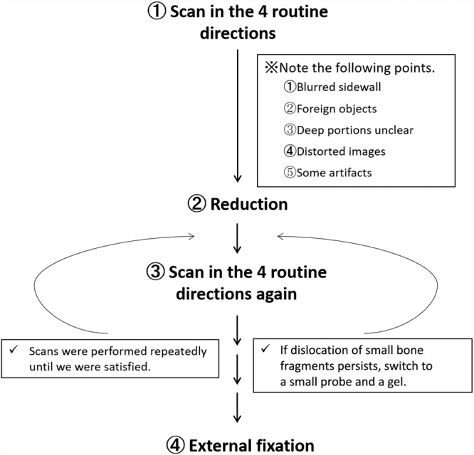
The protocol of our methods.
Thus, all artifacts and blurred images, except the mysterious shadows, could be avoided by adding some small changes.
Our method was used for evaluating preoperatively, intraoperatively, and postoperatively under general anesthesia for cases diagnosed with nasal bone fracture by CT. The statistical analysis was done based on the CT scans. In the 6 cases, fractures were unclear due to some artifacts and there were false-negative results. Therefore, the sensitivity was 6/(70 + 6) = 92.1%. Because there were no misdiagnosed cases, the specificity was 76/ (76 + 0) = 100%. As a result, the PPV was 100% and the NPV was 92.7% (Table 4).
Table 4.
The Statistical Analysis of Ultrasonography with Water in the Diagnosis of the Nasal Fracture

DISCUSSION
When just applying linear array probe with the body surface, only a small area can be seen because the installation area is small. However, using this method, it is possible to obtain an image of the whole nose bone. That is the greatest value of this method.
Because the probe is used in water in this method without contacting the nose, we must know the physical properties of ultrasound to obtain clear images consistently. Ultrasound signals are attenuated by passing through the medium. The attenuation rate can be calculated by the following relationship: Attenuation volume (dB) = Attenuation index (dB/cm/MHz) × Depth (cm) × Frequency (MHz).13
The greater the depth of the medium, the more ultrasound is absorbed. The larger the attenuation index of the medium, the more signals are absorbed as they pass through the medium. The attenuation index of water is the lowest among the various media (Table 2). Despite the lowest attenuation index of water, absorption of ultrasonographic signals is thought to occur. The deep images in our methods tend to become unclear (Fig. 5). Therefore, the amount of water poured should be limited.
It is assumed with ultrasound signals that an echo returns to the transducer after a single reflection and that the depth of an object is related to the time for this round trip. These assumptions are often not maintained in clinical situations, and echoes may be displayed erroneously and perceived as artifacts.15,16 We had 6 groups of blurred or artifact images in our series. Multiple equally spaced signals extending into the deep field were recognized (Fig. 7). The parallel shadows under the nasal bone images were caused by multiple reflections.15,16 This phenomenon occurs where the reflected ultrasound signal on the flat nasal bone is reflected again by the probe. Blurred images of part of the nasal side walls were noted. They were thought to be caused by reflection and interference of the ultrasound signals.15,16 They were improved by tilting the probe parallel to the plane of the desired image (Fig. 3).
Mysterious objects seemed to be present in the water beside the nasal bone (Fig. 8). The ultrasound beams except for the main beams have weak side lobes. The mysterious objects were thought to be artifact images caused by these side lobes.15,16
However, the artifact images do not affect the diagnosis of the nasal fracture or its evaluation after reduction.
The attenuation index of air or bone is higher than that of water (Table 2). The nose has a nasal cavity and septum beneath the nasal bone. These may not be seen clearly because bone and air in the nasal cavity absorb ultrasound signals (Fig. 2). For lesions of the septum and nasal cavities (e.g., hematoma and septal deviation), ultrasonography is less useful than computed tomography. Accordingly, ultrasonography is suitable for the diagnosis of nasal bone fracture and for evaluation after closed reduction. Our methods can provide clear images of the entire nasal bone and neighboring bones, such as maxillary, zygomatic, and frontal bones, in 1 field by using a linear array probe. Moreover, water is cheap and has the lowest attenuation index. However, this method takes a little effort and requires general anesthesia. And because the probe is floating in the water, it tends to be unstable, and a shaking probe may cause distorted images (Fig. 7). Special care must be taken to stabilize the probe. The use of a small probe and a gel can detect local nasal small bone fragments. On the other hand, there may be redislocation due to pressure by the probe after reduction. Our method is recommended as a final step for confirming a good position after reduction.
Our protocols are shown in Figure 9. First, a probe is scanned in 4 different directions while noting the following 4 points.
1) To reduce the attenuation due to reflection, it is preferable to tilt the probe parallel to the plane of the desired image.
2) The probe should be kept close to the nose.
3) Water should be poured slowly.
4) The probe should be kept stable.
After reduction, the probe is scanned in 4 different directions again.
Scanning must be performed repeatedly until satisfactory reduction is obtained.
If dislocation of small bone fragments persists, a small probe and a gel can be selected. Finally, to see the whole picture, the use of our method is recommended to confirm good reduction.
The importance of this study lies in its ability to show an alternative screening test in children and pregnant women, as sonography could be a primary diagnostic technique for evaluating nasal fracture without radiation. The further usefulness can be expected by improving these points and obtaining clearer images.
CONCLUSIONS
We used water as the coupling medium for ultrasonography in nasal bone fracture. This method can provide a clear image in 1 field of the entire nasal bone and its surrounding bones. There were 6 patterns of blurred images impacting the diagnosis and evaluation of reduction. These were described, and their causes were analyzed. Almost all of them could be avoided by adding some small corrections as shown below.
1) The blurred images of the side wall were improved by tilting the probe parallel to the plane of the desired image.
2) Air bubbles can be avoided by pouring the water slowly.
3) The quality of the images improved when the probe was moved closer to the nose.
4) Distorted images were improved by stabilizing the probe.
5) Parallel shadows under the nasal bone images were caused by multiple reflections. If the probe was tilted a little, the parallel shadows disappeared.
6) Mysterious shadows are artifacts caused by side lobes. This phenomenon cannot be avoided.
Footnotes
Presented in part at the 13th Japan-Korea Congress of Plastic and Reconstructive Surgery, 2016, Kanazawa, Japan.
Disclosure: The authors have no financial interest to declare in relation to the content of this article. The Article Processing Charge was paid by the authors.
REFERENCES
- 1.Forrest CR, Lata AC, Marcuzzi DW, et al. The role of orbital ultrasound in the diagnosis of orbital fractures. Plast Reconstr Surg. 1993;92:28–34.. [DOI] [PubMed] [Google Scholar]
- 2.Hirai T, Manders EK, Nagamoto K, et al. Ultrasonic observation of facial bone fractures: report of cases. J Oral Maxillofac Surg. 1996;54:776–779; discussion 779.. [DOI] [PubMed] [Google Scholar]
- 3.Kiwanuka E, Smith SE, Frates MC, et al. Use of high-frequency ultrasound guidance for intraoperative zygomatic arch fracture reduction. J Craniofac Surg. 2013;24:2036–2038.. [DOI] [PubMed] [Google Scholar]
- 4.Gateno J, Miloro M, Hendler BH, et al. The use of ultrasound to determine the position of the mandibular condyle. J Oral Maxillofac Surg. 1993;51:1081–1086; discussion 1086.. [DOI] [PubMed] [Google Scholar]
- 5.Mohammadi A, Javadrashid R, Pedram A, et al. Comparison of ultrasonography and conventional radiography in the diagnosis of nasal bone fractures. Iran J Radiol Reconstr Surg. 2009;6:7–11.. [Google Scholar]
- 6.Lee MH, Cha JG, Hong HS, et al. Comparison of high-resolution ultrasonography and computed tomography in the diagnosis of nasal fractures. J Ultrasound Med. 2009;28:717–723.. [DOI] [PubMed] [Google Scholar]
- 7.Mohammadi A, Ghasemi-Rad M. Nasal bone fracture—ultrasonography or computed tomography? Med Ultrason. 2011;13:292–295.. [PubMed] [Google Scholar]
- 8.Hong HS, Cha JG, Paik SH, et al. High-resolution sonography for nasal fracture in children. AJR Am J Roentgenol. 2007;188:W86–W92.. [DOI] [PubMed] [Google Scholar]
- 9.Park CH, Joung HH, Lee JH, et al. Usefulness of ultrasonography in the treatment of nasal bone fractures. J Trauma. 2009;67:1323–1326.. [DOI] [PubMed] [Google Scholar]
- 10.Kim DH, Kim KS. Usefulness of ultrasonography-assisted closed reduction for nasal fracture under local anesthesia. Arch Craniofac Surg. 2015;16:151–153.. [DOI] [PMC free article] [PubMed] [Google Scholar]
- 11.Ishisaka T, Tanaka K. A study on the concomitant use of acoustic coupling medium for intraoperative diagnostic ultrasound during reduction of facial bone fractures. J Jpn Cranio-Max-Fac Surg. 2013;29:55–63.. [Google Scholar]
- 12.Hirata A, Endo T, Ueno S, et al. Evaluation of nasal bone reduction using ultrasonography. J Jpn Cranio-Max-Fac Surg. 2013;29:64–71.. [Google Scholar]
- 13.Shigemura Y, Akamatsu J, Sugita N, et al. Water can make the clearest ultrasonographic image during reduction of nasal fracture. Plast Reconstr Surg Glob Open. 2014;2:e203. [DOI] [PMC free article] [PubMed] [Google Scholar]
- 14.Hoffmann B, Nürnberg D, Westergaard MC. Focus on abnormal air: diagnostic ultrasonography for the acute abdomen. Eur J Emerg Med. 2012;19:284–291.. [DOI] [PubMed] [Google Scholar]
- 15.Feldman MK, Katyal S, Blackwood MS. US artifacts. Radiographics. 2009;29:1179–1189.. [DOI] [PubMed] [Google Scholar]
- 16.Bertrand PB, Levine RA, Isselbacher EM, et al. Fact or artifact in two-dimensional echocardiography: avoiding misdiagnosis and missed diagnosis. J Am Soc Echocardiogr. 2016;29:381–391.. [DOI] [PMC free article] [PubMed] [Google Scholar]