

Abstract
The wetting of microstructured surfaces is studied both experimentally and theoretically. Even relatively simple surface topographies such as grooves with rectangular cross section exhibit a large variety of different wetting morphologies as observed by atomic force microscopy. This polymorphism arises from liquid wedge formation along the groove corners and from contact line pinning along the groove edges. A global morphology diagram is derived that depends only on two system parameters: (i) the aspect ratio of the groove geometry and (ii) The contact angle of the underlying substrate material. For microfluidics, the most interesting shape regimes involve extended liquid filaments, which can grow and shrink in length while their cross section stays essentially constant. Thus, any method by which one can vary the contact angle can be used to switch the length of the filament, as is demonstrated in the context of electrowetting.
Keywords: surface topography, wetting phenomena, microfluidics
Rapid and efficient handling of relatively small amounts of liquids is a crucial requirement in molecular biology or biomedicine, e.g., for decoding the human genome or for analysis of small blood samples. To do this, one would like to construct labs–on–a–chip on the micrometer scale (see, e.g., ref. 1). An obvious prerequisite for such a lab is appropriate compartments for the confinement of very small amounts of liquids. These microcompartments should have some basic properties: they should have a well defined geometry by which one can measure the precise amount of liquid contained in them; they should be able to confine variable amounts of liquid; and they should be accessible in such a way that one can add and extract liquid in a convenient manner.
A variety of concepts has been developed for the construction of such microfluidic systems. In most cases, a solid matrix is used that surrounds micropipes, reservoirs, etc. Here, we explore an alternative system design, namely open microfluidic systems, which contain free liquid/vapor (or liquid/liquid) interfaces. One advantage of these open structures is that they are directly accessible and easy to clean.
There are two general strategies to construct open microfluidic systems. The first one is to chemically pattern planar substrates and to prepare distinct surface domains that differ in their wettability (2–4). The second strategy, explored here, is to use nonplanar surface topographies that can be fabricated by available photolithographic methods. We find that even relatively simple topographies such as grooves with rectangular cross sections already exhibit a large variety of different liquid morphologies such as droplets, filaments, and wedges. A systematic comparison of experimental observations and theoretical calculations reveals, however, that this polymorphism is primarily determined by only two parameters: (i) the aspect ratio X of the groove geometry, i.e., the ratio of the groove depth to the groove width; and (ii) the contact angle θ of the underlying substrate material. For this two–dimensional parameter space, we determine the overall morphology diagram, which contains seven different shape regimes. Therefore, to obtain a certain liquid morphology, one must match surface topography and wettability by a careful choice of the two variables X and θ.
For microfluidics, the most interesting shape regimes involve extended liquid filaments for which the grooves act as confining microcompartments. These filaments can grow and shrink in length while their cross section stays essentially constant. Filaments with small or negative Laplace pressure are globally stable and can tolerate relatively large external pressures. If one combines the grooved surface topography with methods to switch the contact angle, one can vary the filament length in a controlled and reversible manner, as we explicitly demonstrate by electrowetting (5–8).
Materials and Methods
Experimental Procedures and Observations. We first fabricated grooves with rectangular cross section in silicon by using standard photolithographic methods. These grooves are separated by ridges, again with rectangular cross section. The depth d of the grooves was between 100 and 900 nm, and their width w was between 400 nm and 3 μm. Thus, the groove aspect ratio X ≡ d/w was varied between X = 0.04 and X = 0.60. These topographically structured silicon substrates were chemically modified to vary the contact angle θ for low molecular weight polystyrene within the range 5° ≲ θ ≲ 80° (see Supporting Text and Figs. 6–10, which are published as supporting information on the PNAS web site). The liquid structures on top of these substrates were created by vapor condensation of the polystyrene. Finally, these structures were “frozen” by lowering the temperature below the glass transition temperature of the polymer and were then scanned by atomic force microscopy (AFM) in tapping mode as in previous studies (9).
The AFM studies reveal a large variety of different liquid morphologies even though the grooved surface provides a relatively simple topography. This polymorphism, which reflects the interplay between surface topography and wettability, is already apparent from large scale condensation patterns (see Fig. 6). Inspection of these patterns shows that the liquid condensed in the groove exhibits two rather different morphologies, overspilling droplets and extended filaments. In fact, there is a third, qualitatively distinct, morphology which becomes visible if one increases the resolution of the AFM. One then observes thin liquid wedges along the groove corners (between the groove bottom and the groove sidewalls) as shown in Fig. 1 d–f.
Fig. 1.

AFM images of liquid structures in grooves with rectangular cross section. The six morphologies correspond to six different substrates, which differin the aspect ratio X of their grooves and in their contact angle θ (given in degrees). The experimental uncertainty in X is of the order of a few percent. The morphologies in Upper and Lower are observed for substrates with contact angle θ > 45° and θ < 45°, respectively. For θ > 45°, one observes overspilling droplets that have spread onto the ridges (a), extended filaments with positive Laplace pressure (b), and extended filaments with negative Laplace pressure (c). For θ < 45°, one observes droplets (d) and filaments (e and f) that are connected to thin liquid wedges along the groove corners. In e, the filaments have positive Laplace pressure; in f, this pressure is negative.
The liquid filaments and wedges are always confined to the grooves, whereas large droplets spill over the groove edges and spread onto the neighboring ridges. Furthermore, the liquid/vapor interface or meniscus, which bounds these liquid structures, is curved either toward the vapor or toward the liquid, which corresponds to positive or negative Laplace pressure, respectively. Droplets are always curved toward the vapor and, thus, are characterized by positive Laplace pressure. Wedges are typically curved toward the liquid and then exhibit negative pressure. Filaments, on the other hand, can have positive or negative pressure, as will become clear below.
Close inspection of the AFM micrographs reveals two additional, more subtle, features of these wetting morphologies. First, for θ < 45°, all morphologies seem to involve liquid wedges along the groove corners even though these wedges are sometimes difficult to detect and to distinguish from the groove sidewalls. Second, the contact lines of the droplets, filaments, and wedges consist of two different types of segments: the first type is located on the planar parts of the substrate surface (i.e., on groove bottom, groove sidewalls, or ridge surface), whereas the second type of contact line segment is pinned to the groove edges (between the groove sidewalls and the ridges).
Theoretical Considerations and Calculations. To understand these different morphologies in a systematic and quantitative way, we first observe that the liquid structures considered here are so small that one can ignore the effects of gravity. In such a situation, the liquid/vapor interfaces bounding these liquid structures have two general properties. First, the mean curvature, M, of such an interface is determined by the balance between the Laplace pressure PLa and the interfacial tension Σ, as described by the classical Laplace equation 2MΣ = PLa (10). For a given liquid morphology, both the Laplace pressure and the interfacial tension are constant, which implies that the mean curvature is constant as well. Thus, the droplets, filaments, and wedges are all bounded by liquid/vapor interfaces or menisci that have constant mean curvature. Second, those contact line segments, which are located on the planar parts of the substrate surface, exhibit the unique contact angle θ of the underlying substrate material. However, this value of the contact angle does not, in general, apply to pinned contact line segments, as previously shown for wetting on chemically patterned surfaces (11).
If one condenses only a small amount (or volume) of liquid within the groove, this liquid prefers to sit in the groove corners because it can then be in contact both with the groove bottom and with the groove sidewalls. However, the actual shape that is attained by this small amount of liquid exhibits two θ regimes with qualitatively different behavior. For contact angle θ < 45°, the liquid spreads along the groove corners over the whole length of the groove and forms thin corner wedges (cW); see Fig. 1e. For θ > 45°, on the other hand, the liquid forms corner droplets (cD) which are spatially localized; see Fig. 1a. Thus, if one increased the contact angle θ from a value below 45° to a value above 45°, the two corner wedges would undergo the classical Rayleigh–Plateau instability. The boundary value of 45° follows from the general stability criterion for capillary surfaces as obtained by Concus and Finn (12). An analogous distinction applies to single wedges that are formed in grooves with triangular cross section as discussed by Shuttleworth and Bailey (13): If the cross section of the groove has the form of an isosceles triangle with basal angle 180° – 2ψ, the boundary value of the contact angle θ is equal to ψ.
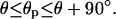
Now, let us increase the liquid volume, which implies that the upper contact line segments of the corner droplets or corner wedges move up the groove sidewalls until they reach the groove edges. These contact line segments then become pinned at the edges, and one obtains pinned droplets (pD) and pinned wedges (pW) as shown in Fig. 2 b and f, respectively. Along the pinned contact line segments, the contact angle θp does not have a unique value but can vary within the whole range
 |
[1] |
Indeed, the contact angle θp is initially equal to θ, when the contact line arrives at the groove edge, but increases continuously with further increase of the liquid volume. As the pinned droplets or wedges grow, they eventually merge, and the liquid is then reorganized into larger structures.
Fig. 2.

Sideviews of wetting morphologies in surface grooves with rectangular cross section. The top row corresponds to substrates with contact angle θ > 45°, the bottom row to θ < 45°. In both cases, the liquid volume increases from the left to the right. For θ > 45°, the liquid forms corner droplets (cD), pinned droplets (pD), overspilling droplets (D) which spread onto the ridges, and extended filaments (F). Whereas droplets grow in all three spatial directions, filaments grow unidirectionally parallel to the groove with essentially constant cross sections. For θ < 45°, the liquid forms corner wedges (cW), pinned wedges (pW), overspilling droplets coexisting with pinned wedges (D/pW), and filaments coexisting with pinned wedges (F/pW). The wedges extend over the whole length of the groove. If the contact line runs across a planar segment of the substrate surface, the corresponding contact angle is equal to θ. If the contact line is pinned at the groove edges, its contact angle θp can vary between θ and θ + 90°. The same range of values applies to the filament angle θF which is uniquely determined by the groove aspect ratio X and the substrate contact angle θ.
We have theoretically determined the structures arising from this reorganization by minimizing the liquid free energies. To explicitly calculate the three–dimensional shapes for a certain amount of liquid within the groove, we used the software package surface evolver (14) and similar algorithms. In addition, we have been able to develop an analytical theory that applies to long filaments and wedges and extends previous work on chemically patterned surfaces (15) (see supporting information).
Results and Discussion
Our theoretical studies show that, for θ > 45°, the liquid forms overspilling droplets (D) and extended filaments (F) for small and large aspect ratios X, respectively; the side views of these morphologies are displayed in Fig. 2 c and d. For θ < 45°, on the other hand, these liquid structures are always connected to wedges, either to pinned wedges as shown in Fig. 2 g and h, or to corner wedges if the depth of the groove is sufficiently large compared with its width. The three–dimensional shapes of these different liquid morphologies are shown in Fig. 3.
Fig. 3.

Three-dimensional shapes for liquid morphologies in rectangular grooves as calculated by numerical minimization of the liquid free energy for different values of the aspect ratio X and the contact angle θ (given in degrees). Upper corresponds to contact angle θ > 45°, and Lower corresponds to θ < 45°. In the latter case, the filaments (F) coexist with pinned wedges (pW) or corner wedges (cW) depending on the aspect ratio X. The morphologies are labeled in the same way as in Fig. 2. The liquid is blue, the groove bottoms are dark gray, the groove sidewalls are light gray, and the ridge surfaces are white.
The overspilling droplets spread onto the ridges with fixed contact angle θ and eventually reach the neighboring grooves. The liquid filaments, on the other hand, stay confined within the grooves as one adds more liquid to them. In fact, these filaments have the remarkable property that they grow or shrink in the direction parallel to the groove while their cross section remains essentially unchanged. In such a situation, the cross section of the filament can be characterized by the filament angle θF as defined in Fig. 2d, which represents the contact angle along those contact line segments that are pinned to the groove edges. As the filament grows, its two end caps move along the groove whereas the main body of the filament does not change its shape.
The filament angle θF can be smaller or larger than 90°. For θF > 90°, the Laplace pressure is positive and the liquid meniscus is curved away from the liquid as shown in Fig. 2d. For θF < 90°, on the other hand, the Laplace pressure is negative and the meniscus is curved toward the liquid as in Fig. 2h. The boundary case θF = 90° corresponds to zero Laplace pressure and a planar meniscus.
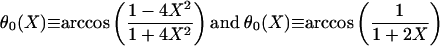
Our analytical theory leads to explicit relationships between the filament angle θF, the groove aspect ratio X, and the substrate contact angle θ (see Supporting Text, Eqs. 1–5). Liquid filaments with θF = 90° and zero Laplace pressure exist only if the aspect ratio X and the contact angle θ satisfy the functional relationship θ = θ0(X) with
 |
[2] |
for 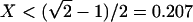 and X > 0.207, respectively.
The functional relationship θ = θ0(X) defines a boundary line within the two–dimensional (X, θ) plane. As one crosses this line, both the Laplace pressure and the free energy of the liquid filaments change sign (see Supporting Text, Eq. 6). This sign change has the remarkable consequence that extended filaments with θF ≤ 90°, which are formed in grooves with θ ≤ θ0(X), are globally stable even for large volumes because they have a lower free energy than localized droplets.
The numerical and analytical calculations are fully consistent with the experimental observations, and both can be combined to construct the overall morphology diagram shown in Fig. 4. In this figure, the full, dashed, and dotted lines represent the boundary and instability lines as obtained by the analytical theory. The small diamonds along those lines correspond to explicit numerical calculations of the three–dimensional boundary shapes. AFM scans were used to experimentally determine the shape of 185 different liquid structures for various values of aspect ratio and contact angle; compare Fig. 1. All of these experimentally observed shapes are fully consistent with the morphology diagram in Fig. 4 (see also Fig. 7).
Fig. 4.

Morphology diagram as a function of groove aspect ratio X and material contact angle θ. The diagram contains seven different regimes, which involve liquid droplets (D), filaments (F), pinned wedges (pW), and corner wedges (cW); compare Figs. 1, 2, 3. The horizontal dotted line corresponds to θ = 45°. The full line on the right of the blue shaded areas corresponds to filaments with zero Laplace pressure as given by Eq. 2: All morphologies above and below this boundary line have positive (+) and negative (–) Laplace pressure, respectively. Filaments (F+) become unstable along the full line on the left. Wedges recede from the groove edges along the dashed line that separates the filament regimes (F–/pW) and (F–/cW). The transition between the regimes (F+/pW) and (F+) occurs within a small coexistence region (see supporting information). The small diamonds along the boundary lines represent numerically calculated shapes. All 185 experimentally determined shapes of individual liquid structures are fully consistent with this diagram.
The morphology diagram in Fig. 4 is divided into two parts by the dotted horizontal line corresponding to contact angle θ = 45°. For contact angle θ < 45°, all morphologies involve thin liquid wedges (W) along the groove corners, whereas such wedges are typically absent for θ > 45° (for 0.071 < X < 0.207, filaments with wedges can be formed for contact angles that are somewhat larger than 45°, as explained in more detail in the supporting information). In the absence of wedges, one encounters three different morphology regimes. For small aspect ratios, the liquid forms overspilling droplets (D) with a lemon–like shape. In this regime, grooves cannot be filled because the liquid will always spill over the groove edges and spread onto the ridges. As one increases the aspect ratio X, one enters the filament regime (F+) where one observes filaments with positive Laplace pressure. For even larger aspect ratio X, one eventually crosses the boundary line as given by Eq. 2, which corresponds to filaments with zero Laplace pressure, and finally enters the filament regime (F–) with negative Laplace pressure.
For contact angle θ < 45°, on the other hand, the overall morphology diagram in Fig. 4 displays four different regimes. For small aspect ratio X, the liquid attains the morphology (D/pW), i.e., overspilling droplets that are connected to pinned wedges along the groove corners. With increasing aspect ratio X, one encounters the regimes (F+/pW), (F–/pW), and (F–/cW) in which filaments with positive and negative Laplace pressure coexist with pinned wedges (pW) or corner wedges (cW).
Even though our experimental studies were performed with a specific substrate and a specific liquid, our theoretical work implies that the morphology diagram as displayed in Fig. 4 is universal and applies to any liquid deposited on grooved surfaces. The precise locations of the boundary and instability lines in Fig. 4 correspond to grooves with rectangular cross sections, but cross sections of different shapes lead to rather similar morphology diagrams (see supporting information). These morphology diagrams can now be used to select specific liquid morphologies by matching the substrate wettability with the groove geometry.
For microfluidics, the most interesting regimes in the morphology diagram are those with θ ≲ θ0(X); compare Eq. 2, which correspond to globally stable filaments with small or negative Laplace pressure. If one wants to use these grooves as microcompartments, one would typically like to avoid the formation of wedges and thus impose the additional condition θ > 45°. In this case, the liquid volume can be directly determined by measuring the filament length because the filaments have a well defined cross section. Furthermore, the grooves can contain a variable amount of liquid because these filaments can grow and shrink in length. Another useful property of filaments with small or negative Laplace pressure is that they can tolerate a relatively large overpressure which is of the order of 2Σ/w. Thus, a water filament in a groove of width w = 5 μm can sustain an overpressure of ≈3 × 10⁴ Pa or 0.3 atm at room temperature.
One direct application of the overall morphology diagram is obtained if one combines the surface topography studied here with methods to switch the contact angle. One such method is provided by electrowetting (5–8); alternative methods are based on substrate surfaces with grafted molecules that exhibit several isomeric conformations and can be switched by light (16–18), temperature (19), or electric potential (20). Thus, let us consider a short filament (F+) with positive Laplace pressure that is in mechanical equilibrium with a larger liquid structure such as a droplet. If we now decrease the contact angle in the groove in such a way that we enter the filament regime (F–) with negative Laplace pressure, the filament imbibes liquid from the large droplet and advances into the groove. If we increase the contact angle again, the Laplace pressure in the filament increases and the liquid filament recedes from the groove. By using electrowetting, it has been possible to demonstrate such a controlled variation of the filament length, as shown in Fig. 5. A more detailed analysis of this system shows that the applied voltage is not constant but decreases along the filament, as will be described elsewhere (J.-C. Baret, M. Decré, S. Herminghaus, and R.S., unpublished work).
Fig. 5.

Optical micrographs of liquid filaments in grooves with aspect ratio X = 1 for three different values of the voltage U. In the absence of the electric field, the contact angle of the substrate is 105°. By applying a voltage of up to 80 V between the droplet and the silicon, the contact angle can be reduced down to 60°. The substrate is silicon covered by an oxide layer and coated with a self-assembled monolayer of octadecyltrichlorosilane (OTS). The conducting liquid consists of a mixture of water, glycerin, and salt. At zero applied voltage, the liquid is expelled from the grooves. Liquid filaments start to advance into the grooves at ≈15 V. As the voltage is further increased, the liquid filaments grow into the grooves. The process is reversible: If one lowers the voltage again, the liquid recedes from the grooves.
In Fig. 5, the contact angle varies between 105° and 60°, which implies that there are no liquid wedges along the groove corners. If we prepared two separate filaments in one groove with a contact angle above 45° and then switched to a contact angle below 45°, the two filaments would fuse by means of the formation of liquid wedges. Thus, we could load the two filaments with different chemical species and then start the chemical reaction by simply switching the contact angle. This latter process might provide a useful route to open microreactors.
Supplementary Material
Acknowledgments
We thank A. Saier for help with the AFM, J. C. Baret for help with the electrowetting experiments, and S. Herminghaus for stimulating discussions. This work was supported by the Deutsche Forschungsgemeinschaft through the Priority Programmes 1052 and 1164 and by the Fonds der Chemischen Industrie, and it made use of the Materials Research Laboratory Central Facilities at the University of California Santa Barbara, which are supported by the Materials Research Science and Engineering Center program of the National Science Foundation under Award DMR00-80034.
Author contributions: R.S., M.B., E.J.K., F.F.L., and R.L. designed research; R.S., M.B., and R.L. performed research; and R.L. wrote the paper.
This paper was submitted directly (Track II) to the PNAS office.
Abbreviation: AFM, atomic force microscopy.
References
- 1.Beebe, D. J., Mensing, G. A. & Walker, G. M. (2002) Annu. Rev. Biomed. Eng. 4, 261–286. [DOI] [PubMed] [Google Scholar]
- 2.Gau, H., Herminghaus, S., Lenz, P. & Lipowsky, R. (1999) Science 283, 46–49. [DOI] [PubMed] [Google Scholar]
- 3.Kataoka, D. & Troian, S. (1999) Nature 402, 794–797. [Google Scholar]
- 4.Wang, J., Zheng, Z. H., Li, H. W., Huck, W. T. S. & Sirringhaus, H. (2004) Nat. Mater. 3, 171–176. [DOI] [PubMed] [Google Scholar]
- 5.Quilliet, C. & Berge, B. (2002) Europhys. Lett. 60, 99–105. [Google Scholar]
- 6.Someya, T., Dodabalapur, A., Gelperin, A., Katz, H. E. & Zhenan, B. (2002) Langmuir 18, 5299–5302. [Google Scholar]
- 7.Mugele, F. & Herminghaus, S. (2002) Appl. Phys. Lett. 81, 2303–2305. [Google Scholar]
- 8.Klingner, A. & Mugele, F. (2004) J. Appl. Phys. 95, 2918–2920. [Google Scholar]
- 9.Seemann, R., Herminghaus, S. & Jacobs, K. (2001) Phys. Rev. Lett. 87, 196101/1–196101/4. [DOI] [PubMed] [Google Scholar]
- 10.Rowlinson, J. & Widom, B. (1989) Molecular Theory of Capillarity (Clarendon, Oxford).
- 11.Lenz, P. & Lipowsky, R. (1998) Phys. Rev. Lett. 80, 1920–1923. [Google Scholar]
- 12.Concus, P. & Finn, R. (1969) Proc. Natl. Acad. Sci. USA 63, 292–299. [DOI] [PMC free article] [PubMed] [Google Scholar]
- 13.Shuttleworth, R. & Bailey, G. L. J. (1948) Disc. Faraday Soc. 3, 16–22. [Google Scholar]
- 14.Brakke, K. (1990) Exp. Math. 1, 141–165. [Google Scholar]
- 15.Brinkmann, M. & Lipowsky, R. (2002) J. Appl. Phys. 92, 4296–4306. [Google Scholar]
- 16.Möller, G., Harke, M. & Motschmann, H. (1998) Langmuir 14, 4955–4957. [Google Scholar]
- 17.Abbott, S., Ralston, J., Reynolds, G. & Hayes, R. (1999) Langmuir 15, 8923–8928. [Google Scholar]
- 18.Ichimura, K., Oh, S.–K. & Nakagawa, M. (2000) Science 288, 1624–1626. [DOI] [PubMed] [Google Scholar]
- 19.de Crevoisier, G., Fabre, P., Corpart, J.–M. & Leibler, L. (1999) Science 285, 1246–1249. [DOI] [PubMed] [Google Scholar]
- 20.Lahann, H., Mitragotri, S., Tran, T.–N., Kaido, H., Sundaram, J., Choi, I. S., Hoffer, S., Somorjai, G. A. & Langer R. (2003) Science 299, 371–374. [DOI] [PubMed] [Google Scholar]
Associated Data
This section collects any data citations, data availability statements, or supplementary materials included in this article.