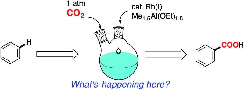
 A detailed mechanistic study of the rhodium-catalyzed carboxylation of aromatic compounds was carried out to clarify the unique characteristics of this reaction.
Abstract
A detailed mechanism of the Rh(i)-catalyzed carboxylation of simple aromatic compounds via C–H bond activation was investigated. Kinetic studies with model compounds of the postulated key intermediates revealed that 14-electron complexes, RhMe(dcype) and RhPh(dcype), participated in the C–H bond activation step and the carboxylation step, respectively. Interestingly, the undesired carboxylation of RhMe(dcype) to give acetic acid was found to be much faster than the desired C–H bond activation reaction under stoichiometric conditions, however, the C–H bond activation reaction could occur under catalytic conditions. Careful controlled experiments revealed that C–H bond activation using RhMe(dcype) became competitive with its direct carboxylation under the condition that the concentration of CO2 in the liquid phase was rather low. This factor could be controlled to some extent by mechanical factors such as the stirring rate and the shape of the reaction vessel. The resting state of the rhodium species under catalytic conditions was found to be [RhCl(dcype)]2, and the proposed intermediates such as RhMe(dcype) and Rh(OBz)(dcype) were readily converted to the most stable state, [RhCl(dcype)]2, via transmetallation with [Al]–Cl species, thus preventing the decomposition of the active catalytic species.
Introduction
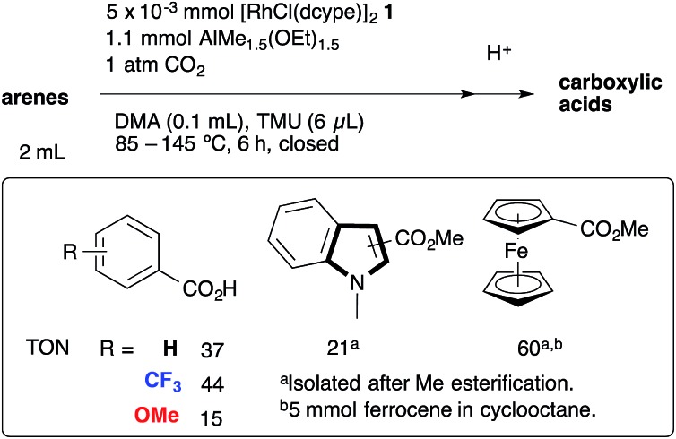
Catalytic direct carboxylation of simple hydrocarbons with carbon dioxide (CO2) is a formidable challenge in organic chemistry.1 Recently, we reported Rh(i)-catalyzed carboxylation of simple aromatic compounds such as benzene and toluene using a combination of [RhCl(dcype)]2 1 (dcype: 1,2-bis(dicyclohexylphosphino)ethane) and AlMe1.5(OEt)1.5 as a stoichiometric methylating agent (Scheme 1).2–4 The most attractive feature of this reaction is its wide generality. Not only electron poor/rich arenes, but also heteroaromatics such as benzofuran and indole were carboxylated successfully. Furthermore, ferrocene showed remarkable reactivity in this reaction.
Scheme 1. Rh-Catalyzed C–H bond carboxylation.
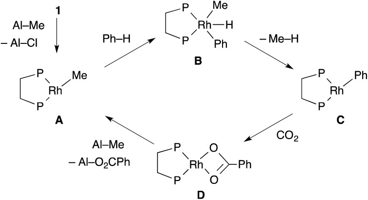
The proposed reaction mechanism is shown in Scheme 2. The reaction starts with the generation of a 14-electron methylrhodium(i) complex A through transmetallation of [RhCl(dcype)]2 1 with AlMe1.5(OEt)1.5, followed by oxidative addition of an sp2 C–H bond of benzene to A, giving phenyl(hydrido)(methyl)rhodium(iii) intermediate B. Reductive elimination of methane from B affords a reactive 14-electron phenylrhodium(i) complex C.5 Nucleophilic addition of C to CO2 gives a rhodium(i) benzoate complex D,6 which is converted to methylrhodium(i) A through transmetallation with AlMe1.5(OEt)1.5.
Scheme 2. Postulated reaction mechanism.
The key to our success consists of three main factors. The first is the choice of methylrhodium(i) as the C–H activation species. It was reported as a stoichiometric reaction by Andersen's and Field's groups that heating or photoirradiating methylrhodium(i) species in benzene afforded the corresponding phenylrhodium(i) species.5 It was expected that by using methylrhodium(i) species, the irreversible dissociation of methane from intermediate B would give the desired arylrhodium(i) species efficiently. The second is the reactivity of RhMe(dcype) A. For the success of the preparation of benzoic acid, direct carboxylation of A to produce acetic acid should be slower than the C–H bond activation of benzene by A. If the direct carboxylation was much faster than the C–H bond activation, the reaction would produce acetic acid only. The third one is the choice of the methylating agent to regenerate A. Methylaluminum was selected because it is widely known to be reactive for transmetallation, but it does not directly react with CO2 under appropriate conditions. Other reagents such as MeMgBr are unsuitable for this reason.
Apart from its synthetic utility, a noteworthy feature of this reaction is the realization of C–H bond activation followed by nucleophilic addition using the combination of a low-valence transition metal catalyst and a stoichiometric alkylating agent. Such C–H bond functionalization strategies are quite limited and most of the reported C–H activation-nucleophilic addition reactions utilize high-valence transition metal complexes such as Rh(iii) for C–H bond activation.7 In 2010, we reported the first example of such reaction, that is, rhodium-catalyzed direct carboxylation of 2-phenylpyridines.8 In 2012, Yoshikai reported a catalytic C–H bond activation of 2-phenylpyridine derivatives using the combination of a cobalt catalyst and a stoichiometric organomagnesium reagent, followed by nucleophilic addition to N-arylimines.9 Very recently, Wang reported that the use of a manganese catalyst with a stoichiometric amount of dimethylzinc was effective for the coupling of 2-phenylpyridines with aldehydes and nitriles.10,11 This kind of catalytic nucleophilic addition is still limited, but would become a powerful methodology in C–H bond functionalization reactions.
As described above, several reactions have recently been reported for this type of C–H activation-nucleophilic addition reactions, however, there has been almost no detailed study on the mechanism of such reactions, probably because of the difficulty in capturing highly reactive alkyl or aryl transition metal intermediates. For example, confirmation of the intermediacy of the 14-electron complexes in the C–H activation and carboxylation steps is not necessarily easy in our reaction because of their instability. As already described, stoichiometric reactivity of relevant methylrhodium(i) species to C–H bond activation has been known for more than three decades, but its detailed mechanistic study has not been carried out.5 Concerning the carboxylation step, there are several reports for stoichiometric carboxylation reactions of arylrhodium(i) complexes,6 however, their mechanisms have been proposed only by theoretical studies.12 Furthermore, transmetallation behaviors and resting states are also left unclarified. In this paper, we report a detailed analysis of the mechanism of this rhodium-catalyzed C–H carboxylation reaction based on kinetic studies using several model compounds, the examination of various reaction conditions including the shape of the reaction vessels and the stirring rate, analysis of the reaction mixture, and some controlled experiments.
Results and discussion
1. Preparation and reactivity of tetracoordinated 16-electron rhodium species
To support the proposed reaction mechanism shown in Scheme 2, we initially tried to prepare each intermediate in the proposed catalytic cycle. In particular, 14-electron complexes RhMe(dcype) A and RhPh(dcype) C were the most attractive because they were thought to be true intermediates in the most important C–H bond activation and carboxylation steps.
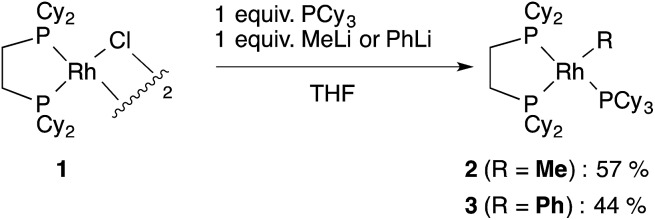
Tricoordinated 14-electron alkylrhodium complexes are known to be so unstable that, up to now, they had not been isolated except for few specific examples.13 Indeed, we initially attempted to prepare them by treating [RhCl(dcype)]2 1 with several methylating agents such as methyllithium, methylmagnesium bromide and trimethylaluminum, however, all of our efforts turned out to be fruitless. Therefore, we decided to prepare the tetracoordinated 16-electron complexes RhMe(PCy3)(dcype) 2 and RhPh(PCy3)(dcype) 3 as appropriate precursors of the 14-electron complexes (Scheme 3).14 2 and 3 were prepared in good yields through the treatment of [RhCl(dcype)]2 with MeLi and PhLi, respectively in the presence of a stoichiometric amount of PCy3.15 Their structures were determined using 1H and 31P NMR. 3 was also characterized using single crystal X-ray structure analysis (see ESI†).
Scheme 3. Preparation of model complexes.
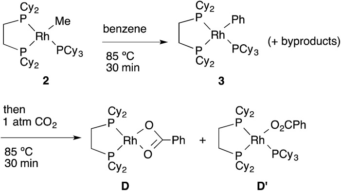
Next, the reactivity of these complexes for the C–H bond activation and carboxylation reactions was examined. To our delight, RhMe(PCy3)(dcype) 2 was found to react with benzene to give RhPh(PCy3)(dcype) 3 under argon at 85 °C with perfect conversion although partial decomposition was also observed (Scheme 4). Moreover, further exposure of this solution to 1 atm CO2 at 85 °C gave a mixture of the carboxylated products Rh(O2CPh)(dcype) D and Rh(O2CPh)(PCy3)(dcype) D′ (D : D′ = 1 : 2 at room temperature). No intermediates were observed in these two reactions. The rhodium benzoates were characterized by comparing their 31P NMR spectra with those of authentic samples of D and D′ (see ESI† for their preparative methods).
Scheme 4. Reactions of model complexes.
2. Mechanistic study on C–H bond activation by methylrhodium(i) species
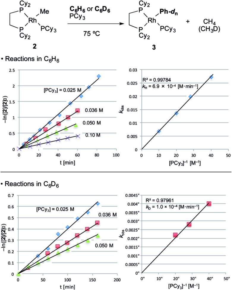
With the suitable model complexes in hand, we carried out a kinetic study of the C–H bond activation step by monitoring the reaction with 1H NMR (Fig. 1). The rate of the C–H bond activation reaction of RhMe(PCy3)(dcype) 2 with benzene-d 0 as a solvent was measured in the presence of various concentrations of PCy3. Fortunately, the addition of PCy3 completely suppressed decomposition of the complex, and the desired transformation proceeded quantitatively according to the 31P NMR spectra (see ESI†).16 The reaction was found to be first order to RhMe(PCy3)(dcype) 2 and inverse first order to PCy3 (eqn (1)).
| –ln([2]/[2]0) = kH(D)[PCy3]–1t | 1 |
k H = 6.9 × 10⁻⁴ [M min–1]k D = 1.0 × 10⁻⁴ [M min–1]k H/k D = 6.9
Fig. 1. Kinetics of C–H bond activation. Conditions: 0.005 mmol 2, 0.50 mL benzene in an NMR tube under argon. The reaction was analyzed using 1H NMR. Consumption of 2 was traced with the decay of the signal at δ = 0.4 (RhCH3). No other products were observed using 31P NMR after the reaction.
The value of –ln([2]/[2]0) was completely proportional to the reaction time even after 90% conversion, and was inversely proportional to [PCy3] with the rate constant k H = 6.9 × 10⁻⁴ [M min–1] at 75 °C. According to the steady state approximation, this reaction includes dissociation of PCy3 before the rate-determining step. In addition, the reaction in benzene-d 6 was apparently slower (k D = 1.0 × 10⁻⁴ [M min–1]) than in benzene-d 0 and the KIE value (k H/k D) was estimated to be 6.9. This large KIE value strongly suggests that the C–H bond activation step is rate-determining in this stoichiometric reaction.
With these results, it was concluded that tricoordinated RhMe(dcype) A is the true intermediate of the C–H bond activation step (Scheme 5). 1H NMR analysis also indicated the formation of CH4 in benzene-d 0, and CH3D in benzene-d 6. The detailed process of C–H bond activation remains unclear through our study, but the oxidative addition–reductive elimination process should be the most plausible. For instance, Sakakura reported that photo-induced reaction of RhICl(PMe3)3 in benzene generated RhIII(H)(Cl)(Ph)(PMe3)3.17,18
Scheme 5. Plausible pathway of the C–H bond activation step.
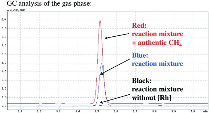
The formation of methane was also confirmed using GC analysis of the reaction mixture under catalytic conditions (Fig. 2). After the catalytic carboxylation of benzene was carried out under optimized conditions using [RhCl(dcype)]2 1 and AlMe1.5(OEt)1.5, the gas phase of the resulting mixture was directly injected into the GC. While no methane formation was observed in the absence of [RhCl(dcype)]2 1, it was detected under catalytic conditions.
Fig. 2. Methane observation using GC analysis. The reaction was carried out in benzene at 85 °C. Detailed reaction conditions were the same as shown in Scheme 1.
We also carried out several KIE studies under catalytic conditions to determine the turnover-limiting step. It should be noted that an accurate kinetic study of this reaction is difficult under our conditions because of the CO2 concentration problem (noted in the later section) and complex disproportionation of the methylaluminum reagent. Therefore, the results described below may not be very precise but are sufficient for general discussion.
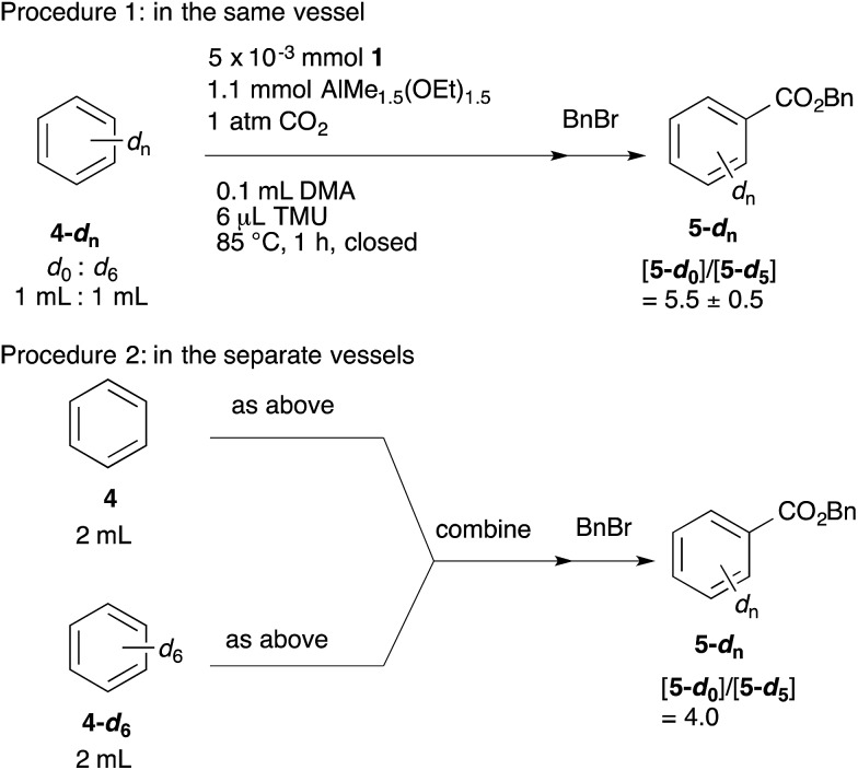
The KIEs were measured using two procedures (Scheme 6). In procedure 1, the reaction was performed using a 1 : 1 mixture of benzene-d 0 and benzene-d 6. In procedure 2, the reactions with benzene-d 0 and benzene-d 6 were carried out in separate vessels, and the resulting mixtures were combined after quenching the reaction with aqueous 1 M HCl. Both reactions were performed at 85 °C for 1 h. The ratio of benzoic acid-d 0 and benzoic acid-d 5 was estimated using 1H NMR after esterification of the benzoic acids with benzyl bromide. As a result, [5-d0]/[5-d5] = 5.5 (procedure 1) and [5-d0]/[5-d5] = 4.0 (procedure 2) were obtained. These large KIE values indicate that the C–H bond activation step is also the turnover-limiting step under catalytic conditions.
Scheme 6. KIE study under catalytic conditions.
3. Mechanistic study of the carboxylation step
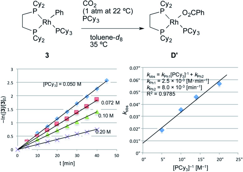
Next, a kinetic study of the carboxylation reaction of RhPh(PCy3)(dcype) 3 was carried out under CO2 (1 atm at 22–23 °C) in the presence of PCy3 in toluene-d 8 (Fig. 3).19 The value of –ln([3]/[3]0) was proportional to the reaction time and was almost inversely proportional to [PCy3] with the rate constant k Ph1 = 2.5 × 10⁻³ [M min–1] at 35 °C (eqn (2)), suggesting that the carboxylation step is much faster than the C–H activation step, which coincided with the results of the KIE studies.
| –ln([3]/[3]0) = (kPh1[PCy3]–1 + kPh2)t | 2 |
k Ph1 = 2.5 × 10⁻³ [M min–1]k Ph2 = 8.0 × 10⁻³ [min–1]
Fig. 3. Kinetics of the carboxylation of 3. Conditions: 0.005 mmol 3, 0.50 mL toluene-d 8 in an NMR tube (ca. 4 mL vol.) under 1 atm CO2. The solution was saturated with CO2 at 22–23 °C beforehand (see ESI†). Consumption of 3 was traced with the decay of the signal at δ 7.9 ppm (Ph). No other products were observed using 31P NMR after the reaction.
Dissociation of PCy3 was also clearly involved in the carboxylation step. The small intercept term k Ph2 = 8.0 × 10⁻³ [min–1] left the possibility of a minor pathway (e.g. the reaction without dissociation of PCy3), but it was trivial at lower concentrations of PCy3. Therefore, it is concluded that the carboxylation step mainly proceeded via 14-electron complex RhPh(dcype) C in a similar manner to the C–H bond activation step (Scheme 7).
Scheme 7. Plausible pathway of the carboxylation step.
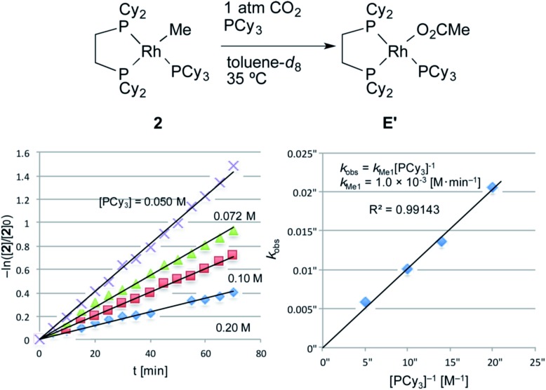
The carboxylation reaction of RhMe(PCy3)(dcype) 2 was also carried out in toluene-d 8 at 35 °C (Fig. 4).20 2 showed a somewhat lower reactivity of carboxylation compared to RhPh(PCy3)(dcype) 3 (eqn (3), k Me1 = 1.0 × 10⁻³ [M min–1] vs. k Ph1 = 2.5 × 10⁻³ [M min–1]).
| –ln([2]/[2]0) = kMe1[PCy3]–1t | 3 |
k Me1 = 1.0 × 10⁻³ [M min–1]
Fig. 4. Kinetics of the carboxylation of 2. Conditions: 0.005 mmol 2, 0.50 mL toluene-d 8 in an NMR tube (ca. 4 mL vol.) under 1 atm CO2. The solution was saturated with CO2 at 22–23 °C beforehand (see ESI†). Consumption of 2 was traced with the decay of the signal at δ 0.4 ppm (CH3).
The equation was similar to that of RhPh(PCy3)(dcype) 3 except for complete disappearance of the intercept term (k Me2 = 0), suggesting the intermediacy of RhMe(dcype) A as a reactive species. 1H and 31P NMR indicated that there was no formation of the C–H activation product Rh(tol)(PCy3)(dcype) or corresponding benzoates throughout the reaction. In addition, the stoichiometric reaction of RhMe(PCy3)(dcype) 2 under 1 atm CO2 in benzene at 85 °C did not give benzoates at all, but gave only acetates Rh(OAc)(dcype) E and Rh(OAc)(PCy3)(dcype) E′ (Scheme 8). These results imply that the carboxylation of RhMe(dcype) A with CO2 proceeded much faster than the C–H activation of A with benzene under 1 atm CO2. In other words, predominant formation of acetic acid should associate with the formation of benzoic acid.
Scheme 8. Stoichiometric carboxylation of 2 at 85 °C.
Based on the above considerations, the TON of acetic acid (AcOH) was estimated using GC analysis under catalytic conditions. According to the standard catalytic procedure, the reaction was carried out in a 40 cm3 test tube for 6 h at 85 °C with the tube kept closed. As we expected, it was found that in addition to ca. 0.40 mmol (TON = 40) of benzoic acid, ca. 0.6 mmol (TON = ca. 60) of acetic acid was produced as judged using GC analysis (Scheme 9). However, the ratio of BzOH : AcOH = 2 : 3 was still inconsistent with the result of the stoichiometric study. To obtain more information on the competitive formation of benzoic acid and acetic acid, we decided to carry out a more detailed analysis of the reactions to clarify the difference of these stoichiometric and catalytic reactions.
Scheme 9. Confirmation of acetic acid formation.
All the reactions so far have been carried out using 40 cm3 test tube (ca. 2 mmol of CO2 should be inside) in a closed system for the catalytic reaction, and ca. 1 mmol of CO2 was consumed to produce benzoic acid and acetic acid as shown in Scheme 9. As the amount of CO2 in the reaction mixture was thought to be influential on the ratio of carboxylic acids under catalytic conditions, the reaction was examined using several vessels with different shapes and volumes.
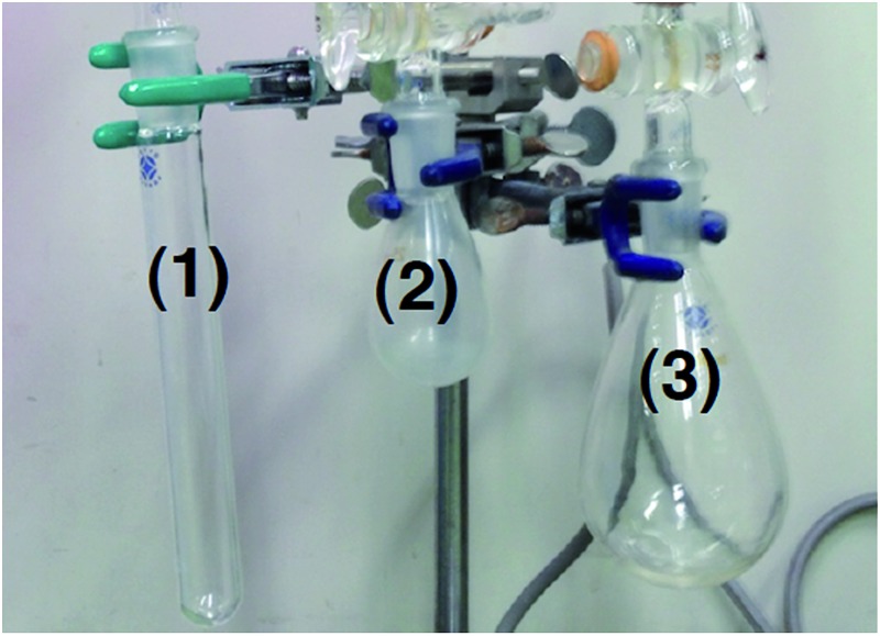
The effect of the reaction vessel was examined by changing the total volume and/or the shape of the reaction vessel (Table 1).21 The reaction time was set to 1 h to reduce the effects of catalyst decomposition and reagent consumption. The stirring rate was kept at ca. 800 rpm. The reaction vessels were; a 40 cm3 test tube (ø = 2 cm, vessel 1) with a closed system (entry 1), a 40 cm3 test tube (vessel 1) with a 2000 cm3 balloon filled with CO2 to disregard the decrease of CO2 in a whole vessel (entry 2), a 40 cm3 round-bottom flask (vessel 2) with a 2000 cm3 balloon (entry 3) and a 160 cm3 round-bottom flask (vessel 3) with a closed system (entry 4). In entry 4, the content of CO2 should also be sufficient (ca. 7 mmol).
Table 1. Effect of the CO2 content and shape of the vessel a .
| |||||
| Entry | Conditions | Total volume (cm3) | TON |
[BzOH]/[AcOH] | |
| [BzOH] | [AcOH] | ||||
| 1 | Vessel 1 | 40 | 7.9 | 68 | 0.12 |
| 2 | Vessel 1 + balloon | 40 + 2000 | 5.7 | 42 | 0.14 |
| 3 | Vessel 2 + balloon | 40 + 2000 | 2.5 | 84 | 0.03 |
| 4 | Vessel 3 | 160 | 1.3 | 147 | 0.01 |
aVessel 1: 40 cm3 test tube (ø = 2 cm), vessel 2: 40 cm3 round-bottom flask, vessel 3: 160 cm3 round-bottom flask. Conditions are shown in Scheme 9, except the reaction time was shortened to 1 h. Stirring rates were approx. 800 rpm.
It was found that the volume of the vessel was not so influential on the ratio of benzoic acid and acetic acid, but the shape of the vessel caused a dramatic difference. The value of [BzOH]/[AcOH] in vessel 1 was 0.12 without a balloon and 0.14 with a balloon (entry 1 vs. 2). This indicated that the total content of CO2 was not responsible for the selectivity during the initial 1 h of reaction time.22 In sharp contrast, the use of vessel 2 decreased [BzOH]/[AcOH] to 0.03 (entry 2 vs. 3). The formation of acetic acid was predominant when vessel 3 was employed (entry 4, [BzOH]/[AcOH] = 0.01) as observed in the reaction of RhMe(PCy3)(dcype) 2 under CO2 in benzene (Scheme 8).
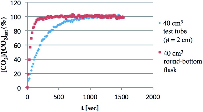
This large effect of the shape of the vessel would be due to the dissolution rate of CO2 into solution, which was elucidated using in situ-IR analysis at room temperature (Fig. 5).23 CO2 dissolution occurred more rapidly in a 40 cm3 round-bottom flask than in a 40 cm3 test tube even though they have almost the same total volume. For instance, the CO2 concentration reached saturation within 200 seconds in the round-bottom flask. On the other hand, it took almost 1000 seconds in the test tube. Although the results shown here were obtained without stirring, the rate of dissolution of CO2 certainly depends on the surface area of the solution, which influenced the ratio of BzOH and AcOH. For the same reason, the stirring rate was also found to be responsible (Table 2). Slower stirring gave an improved ratio of [BzOH]/[AcOH], although the total TON decreased. For example, [BzOH]/[AcOH] was 0.25 and the total TON was 41 at 100 rpm, while [BzOH]/[AcOH] was 0.07 and the total TON was 99 at 1000 rpm.
Fig. 5. Dissolution of CO2 in toluene. Dissolution of CO2 was traced using in situ-IR spectrometry (2350 cm–1) in 2 cm3 toluene at room temperature. The mixtures were stood without stirring during measurement.
Table 2. Effect of stirring rate a .
| Entry | Rate [rpm] | TON |
[BzOH]/[AcOH] | |
| [BzOH] | [AcOH] | |||
| 1 | 100 | 8.3 | 33 | 0.25 |
| 2 | 800 | 7.9 | 68 | 0.12 |
| 3 | 1000 | 6.2 | 93 | 0.07 |
aReactions were carried out in 40 cm3 test tubes (closed system). Conditions were the same as noted in Table 1.
From these results, it was concluded that this reaction strongly depends on CO2 concentration in the liquid phase, which was mainly determined by the dissolution rate of CO2. In other words, the liquid phase is not saturated with CO2 owing to its fast consumption by carboxylation reactions under catalytic conditions. In the presence of sufficient CO2, intermediate RhMe(dcype) A mostly reacts with CO2 to give acetic acid before it reacts with benzene to give RhPh(dcype) C, as observed in entry 4 in Table 1 and entry 3 in Table 2, and this agrees with the result of the stoichiometric reaction of RhMe(PCy3)(dcype) 2 in CO2-saturated benzene. However, the true concentration of CO2 should be rather low under catalytic conditions particularly with slower stirring and a liquid phase with a smaller surface area. Carboxylation and C–H bond activation of benzene by RhMe(dcype) A becomes competitive under such conditions, and both benzoic acid and acetic acid were obtained catalytically in contrast to the stoichiometric reaction of RhMe(PCy3)(dcype) 2.
In summary, we proved that 14-electron tricoordinated RhPh(dcype) C is a plausible intermediate in the carboxylation step. RhMe(dcype) A also reacted with CO2 in a similar way to give acetic acid catalytically. This undesired pathway was predominant over the desired C–H bond activation reaction under 1 atm CO2. Nevertheless, C–H bond activation of benzene took place successfully under catalytic conditions because the concentration of CO2 in the liquid phase was much lower than saturation due to its consumption by the carboxylation reaction of RhMe(dcype) A. Thus, the dissolution rate of CO2 controlled the fate of the key intermediate RhMe(dcype) A. This clearly indicates that the balance between C–H bond activation and the subsequent transformation is very important for the catalytic C–H bond functionalization reaction using these alkyl metal complexes.
4. Transmetallation behaviors
Direct observation of the reaction mixture is a reliable method to obtain information on the resting state of the catalytic cycle. We then observed 31P NMR to clarify the rhodium species present in the reaction mixture after the catalytic reaction was carried out in benzene for 1 h under 1 atm CO2 at 85 °C (Scheme 10). It was a surprise to find that almost no complex except for the starting [RhCl(dcype)]2 1 was observed even though benzoic acid was produced gradually. Alternatively, under argon only 1 was observed. No methylrhodium or phenylrhodium species were observed. [RhCl(dcype)]2 1 mostly decomposed after 6 h of heating under Ar. Therefore, it was speculated that there would be equilibria between A–D and 1, so that only 1 was observable.
Scheme 10. Analysis of the reaction mixture using 31P NMR.
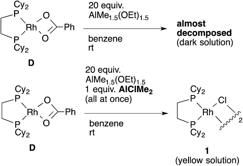
To confirm our speculation, Rh(O2CPh)(dcype) D was prepared and its catalytic activity was examined. When the catalytic carboxylation reaction of benzene was carried out using D as a catalyst, benzoic acid was obtained with a TON of only 2.5. In addition, when D and excess AlMe1.5(OEt)1.5 were mixed in benzene at room temperature (no chloride source), rapid decomposition of the complex was observed using 31P NMR (Scheme 11). However, it was found that addition of only an equimolar amount of AlClMe2 to D prevented it from decomposition to give [RhCl(dcype)]2 1, and the catalytic activity was recovered (TON = 28). In other words, the success of the present reaction was due to the fast transmetallation of rather unstable [Rh]–O2CPh or [Rh]–Me with [Al]–Cl to give a stable dimeric [Rh]–Cl species under catalytic conditions.
Scheme 11. Transmetallation of Rh–O2CPh complex.
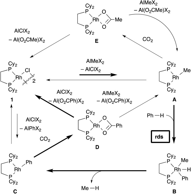
The total figure of this reaction is illustrated in Scheme 12. The most important cycle, which provides benzoic acid, is confirmed to be fundamentally the same as we postulated (depicted in bold arrows). First, transmetallation of [RhCl(dcype)]2 1 and AlMe1.5(OEt)1.5 generates the 14-electron methylrhodium complex, RhMe(dcype) A. A reacts with benzene to give the 14-electron phenylrhodium complex, RhPh(dcype) C, possibly via reductive elimination of methane from Rh(H)(Me)(Ph)(dcype) B. The following carboxylation of C provides rhodium benzoate Rh(O2CPh)(dcype) D. There are two possible pathways in the next step. Transmetallation of D and chloroaluminum species converts the catalyst back to [RhCl(dcype)]2 A, or transmetallation of D and methylaluminum species directly gives RhMe(dcype) A. However, the generated A could be converted to the most thermodynamically stable 1 via further transmetallation because of the equilibrium between 1 and A.24,25 In addition, there is a branch in this reaction. A reacts with CO2 to give Rh(OAc)(dcype) E in the same manner as C. Therefore, this reaction provides a mixture of acetic acid and benzoic acid.
Scheme 12. Total figure of the catalytic cycle.
The undesired formation of E should be operative if the reaction mixture contains a sufficient amount of CO2 in solution. Nevertheless, the desired C–H bond activation takes place because the true concentration of CO2 in solution is much lower than saturation. Importantly, the catalytic reaction did not work well in the absence of the chloride source. This is probably because the tricoordinated active species, RhMe(dcype) A was too unstable to be present at a higher concentration and decomposition of the Rh species occurred. The presence of chloride species keeps the resting state of the rhodium species as [RhCl(dcype)]2 1, which has a stable tetracoordinated dimeric structure and moderately reactive to transmetallation with the Al–Me species. This equilibrium limited the concentration of the active species, RhMe(dcype) A, and suppressed its decomposition. Transmetallation steps have attracted less interest in mechanistic studies, and their possible equilibria are mostly ignored. Our observation should be an interesting example to show the importance of the transmetallation equilibria in the catalytic cycle.
Conclusions
This article describes a detailed mechanistic analysis of the rhodium-catalyzed carboxylation of simple aromatic compounds. Although no active intermediates were observable at all in this reaction, the proposed mechanism was mostly supported by several experiments. Most importantly, elucidation of the active species was achieved by designing appropriate precursors, and carrying out kinetic studies. 14-Electron rhodium complexes were found to be the key intermediates in both the C–H bond activation and carboxylation steps. The presence of such species was also supported by the formation of methane and acetic acid. KIE studies under catalytic conditions revealed that the C–H bond activation step was the turnover-limiting step. According to kinetic studies, this C–H bond activation step should be a minor pathway in the presence of a sufficient amount of CO2 because of undesired predominant carboxylation of the RhI–Me species. However, further analysis revealed that this problem could be overcome to some extent by mechanical factors such as stirring rate and the shape of the reaction vessel, because undesired carboxylation of the RhI–Me species could be made slower by controlling the concentration of CO2 in solution. Finally, it was found that reversible transmetallation pathways to give [RhCl(dcype)]2 1 contributed to suppress decomposition of the catalyst. This study will provide new possibilities in such C–H bond functionalization reactions using alkyl-metal species and transition metal-catalyzed carboxylation reactions.
Acknowledgments
This research was supported by JSPS KAKENHI, grant number 24245019, and the ACT-C program from JST. T. S. thanks JSPS for the fellowship.
Footnotes
References
- Representative reviews on the carboxylation of organic compounds: ; (a) Sakakura T., Choi J.-C., Yasuda H. Chem. Rev. 2007;107:2365–2387. doi: 10.1021/cr068357u. [DOI] [PubMed] [Google Scholar]; (b) Riduan S. N., Zhang Y. Dalton Trans. 2010;39:3347–3357. doi: 10.1039/b920163g. [DOI] [PubMed] [Google Scholar]; (c) Cokoja M., Bruckmeier C., Rieger B., Herrmann W. A., Kühn F. E. Angew. Chem., Int. Ed. 2011;50:8510–8537. doi: 10.1002/anie.201102010. [DOI] [PubMed] [Google Scholar]; (d) Huang K., Sun C.-L., Shi Z.-J. Chem. Soc. Rev. 2011;40:2435–2452. doi: 10.1039/c0cs00129e. [DOI] [PubMed] [Google Scholar]; (e) Wenzhen Z., Xiaobing L. Chin. J. Catal. 2012;33:745–756. [Google Scholar]; (f) Tsuji Y., Fujihara T. Chem. Commun. 2012;48:9956–9964. doi: 10.1039/c2cc33848c. [DOI] [PubMed] [Google Scholar]; (g) Omae I. Coord. Chem. Rev. 2012;256:1384–1405. [Google Scholar]; (h) Cai X., Xie B. Synthesis. 2013;45:3305–3324. [Google Scholar]; (i) Takaya J. and Iwasawa N., Science of Synthesis, C-1 Building Blocks in Organic Synthesis, 2014, vol. 1, pp. 281–307. [Google Scholar]; (j) Liu Q., Wu L., Jackstell R., Beller M. Nat. Commun. 2015;6:5933. doi: 10.1038/ncomms6933. [DOI] [PubMed] [Google Scholar]
- Suga T., Mizuno H., Takaya J., Iwasawa N. Chem. Commun. 2014;50:14360–14363. doi: 10.1039/c4cc06188h. [DOI] [PubMed] [Google Scholar]
- For catalytic C–H bond carboxylation of relatively acidic aromatic compounds, see: ; (a) Boogaerts I. I. F., Nolan S. P. J. Am. Chem. Soc. 2010;132:8858–8859. doi: 10.1021/ja103429q. [DOI] [PubMed] [Google Scholar]; (b) Boogaerts I. I. F., Fortman G. C., Furst M. R. L., Cazin C. S. J., Nolan S. P. Angew. Chem., Int. Ed. 2010;49:8674–8677. doi: 10.1002/anie.201004153. [DOI] [PubMed] [Google Scholar]; (c) Zhang L., Cheng J., Ohishi T., Hou Z. Angew. Chem., Int. Ed. 2010;49:8670–8673. doi: 10.1002/anie.201003995. [DOI] [PubMed] [Google Scholar]; (d) Boogaerts I. I. F., Nolan S. P. Chem. Commun. 2011;47:3021–3024. doi: 10.1039/c0cc03890c. [DOI] [PubMed] [Google Scholar]; (e) Inomata H., Ogata K., Fukuzawa S., Hou Z. Org. Lett. 2012;14:3986–3989. doi: 10.1021/ol301760n. [DOI] [PubMed] [Google Scholar]
- AlMe1.5(OEt)1.5 was prepared from AlMe3 with 2 equiv. of EtOH. The 1 : 1 sharp peaks of the methyl group and ethoxy group indicate this composition and its discrete structure. A tetramer structure has been postulated for the related compound. See: Turunen J., Pakkanen T. T., Löfgren B., J. Mol. Catal., 1997, 123 , 35 –42 , and ref. 2 . [Google Scholar]
- Examples of stoichiometric C–H bond activation by alkylrhodium(i) complexes: ; (a) Price R. T., Andersen R. A., Muetterties E. L. J. Organomet. Chem. 1989;376:407–417. [Google Scholar]; (b) Boyd S. E., Field L. D., Hambley T. W., Partridge M. G. Organometallics. 1993;12:1720–1724. [Google Scholar]
- Stoichiometric carboxylation of arylrhodium(i) complexes: ; (a) Kolomnikov I. S., Gusev A. O., Belopotapova T. S., Grigoryan M. K., Lysyak T. V., Struchkov Y. T., Vol'pin M. E. J. Organomet. Chem. 1974;69:C10–C12. [Google Scholar]; (b) Darensbourg D. J., Grötsch G., Wiegreffe P., Rheingold A. L. Inorg. Chem. 1987;26:3827–3830. [Google Scholar]
- Yang L., Huang H. Chem. Rev. 2015;115:3468–3517. doi: 10.1021/cr500610p. [DOI] [PubMed] [Google Scholar]
- Mizuno H., Takaya J., Iwasawa N. J. Am. Chem. Soc. 2011;133:1251–1253. doi: 10.1021/ja109097z. [DOI] [PubMed] [Google Scholar]
- (a) Gao K., Yoshikai N. Chem. Commun. 2012;48:4305–4307. doi: 10.1039/c2cc31114c. [DOI] [PubMed] [Google Scholar]; (b) Gao K., Paira R., Yoshikai N. Adv. Synth. Catal. 2014;356:1486–1490. [Google Scholar]
- Zhou B., Hu Y., Wang C. Angew. Chem., Int. Ed. 2015;54:13659–13663. doi: 10.1002/anie.201506187. [DOI] [PubMed] [Google Scholar]
- For addition to aldehydes using silanes as stoichiometric reductants, see: ; (a) Fukumoto Y., Sawada K., Hagihara M., Chatani N., Murai S. Angew. Chem., Int. Ed. 2002;41:2779–2781. doi: 10.1002/1521-3773(20020802)41:15<2779::AID-ANIE2779>3.0.CO;2-J. [DOI] [PubMed] [Google Scholar]; (b) Kuninobu Y., Nishina Y., Takeuchi T., Takai K. Angew. Chem., Int. Ed. 2007;46:6518–6520. doi: 10.1002/anie.200702256. [DOI] [PubMed] [Google Scholar]; (c) Li B.-J., Shi Z.-J. Chem. Sci. 2011;2:488–493. [Google Scholar]
- (a) Ostapowicz T. G., Hölscher M., Leitner W. Chem.–Eur. J. 2011;17:10329–10338. doi: 10.1002/chem.201101463. [DOI] [PubMed] [Google Scholar]; (b) Qin H.-L., Han J.-B., Hao J.-H., Kantchev E. A. B. Green Chem. 2014;16:3224–3229. [Google Scholar]; (c) Vummaleti S. V. C., Talarico G., Nolan S. P., Cavallo L., Poater A. Org. Chem. Front. 2016;3:19–23. [Google Scholar]
- . For other 14-electron rhodium complexes, see: ; (a) Urtel H., Meier C., Eisenträger F., Rominger F., Joschek J. P., Hofmann P. Angew. Chem., Int. Ed. 2001;40:781–784. doi: 10.1002/1521-3773(20010216)40:4<781::aid-anie7810>3.0.co;2-t. [DOI] [PubMed] [Google Scholar]; (b) Werlé C., Bailly C., Karmazin-Brelot L., Le Goff X.-F., Pfeffer M., Djukic J.-P. Angew. Chem., Int. Ed. 2014;53:9827–9831. doi: 10.1002/anie.201405240. [DOI] [PubMed] [Google Scholar]; (c) Zhao P., Krug C., Hartwig J. F. J. Am. Chem. Soc. 2005;127:12066–12073. doi: 10.1021/ja052473h. [DOI] [PubMed] [Google Scholar]; (d) Chaplin A. B. Organometallics. 2014;33:624–626. [Google Scholar]; (e) Whited M. T., Kosanovich A. J., Janzen D. E. Organometallics. 2014;33:1416–1422. [Google Scholar]; (f) Hasegawa M., Segawa Y., Yamashita M., Nozaki K. Angew. Chem., Int. Ed. 2012;51:6956–6960. doi: 10.1002/anie.201201916. [DOI] [PubMed] [Google Scholar]
- Similar strategies to stabilize 14-electron complexes in mechanistic studies: ; (a) Hayashi T., Takahashi M., Takaya Y., Ogasawara M. J. Am. Chem. Soc. 2002;124:5052–5058. doi: 10.1021/ja012711i. [DOI] [PubMed] [Google Scholar]; (b) Krug C., Hartwig J. F. Organometallics. 2004;23:4594–4607. [Google Scholar]
- Hofmann P., Meier C., Hiller W., Heckel M., Riede J., Schmidt M. U. J. Organomet. Chem. 1995;490:51–70. [Google Scholar]
- Considered from this stabilization effect of PCy3, the role of DMA under catalytic conditions might be suppression of the catalyst decomposition. Presumably, it weakly coordinates to the vacant site of unstable 14-electron complexes
- Choi J.-C., Sakakura T. J. Am. Chem. Soc. 2003;125:7762–7763. doi: 10.1021/ja021375i. [DOI] [PubMed] [Google Scholar]
- GC analysis of the liquid phase revealed the formation of a very small amount of toluene (0.002 mmol, TON = 0.2), which might be generated by undesired reductive elimination from Rh(H)(Me)(Ph)(dcype) B
- Insufficient introduction of CO2 led to irreproducible results. See ESI for the practical experimental procedure
- According to 31P NMR analysis, the reaction mixture included a small amount of Rh(OAc)(dcype) E at lower concentrations of PCy3 and this affected the concentration of free PCy3. But this was trivial, so that linear correlation was mostly maintained throughout the experiment
- It should be noted that we used Chemistation™ (Tokyo Rikakikai Co. Ltd.) for heating a reaction mixture in other experiments including Scheme 9. This apparatus cools the system just above the liquid phase to maintain gentle reflux. On the other hand, experiments in Tables 1 and 2 were carried out in an oil bath, which does not have a cooling system for practical reasons. Such small differences also affected the results. For example, the TONs of BzOH and AcOH were 15 and 54 respectively, when the reaction in entry 1 (Table 1) was carried out using Chemistation™
- A decrease in CO2 should affect the results over longer reaction times. The amount of acetic acid in Scheme 9 (TON = 60) suggests that not as much acetic acid forms during the later stages of the reaction
- The experiments at higher temperatures were unsuccessful owing to the sensitivity of our equipment
- Addition of an appropriate ligand enables the observation of a methylrhodium(i) complex in such Rh–Cl/Al–Me transmetallation equilibrium. For example, the reaction of RhCl(PCy3)(dcype) F with AlMe3 gave RhMe(PCy3)(dcype) 2 as a major product:
 Interestingly, the use of AlMe1.5(OEt)1.5 resulted in no reaction under the similar conditions. These results might be related to the better results obtained using the latter reagent in the carboxylation reaction (ref. 2)
 - There would also be an equilibrium between 1 and RhPh(dcype) C in a similar manner
Associated Data
This section collects any data citations, data availability statements, or supplementary materials included in this article.


