Abstract
Contrast-enhanced computed tomography (CECT) helps enhance the visibility for tumor imaging. When a high-Z contrast agent interacts with X-rays across its K-edge, X-ray photoelectric absorption would experience a sudden increment, resulting in a significant difference of the X-ray transmission intensity between the left and right energy windows of the K-edge. Using photon-counting detectors, the X-ray intensity data in the left and right windows of the K-edge can be measured simultaneously. The differential information of the two kinds of intensity data reflects the contrast-agent concentration distribution. K-edge differences between various matters allow opportunities for the identification of contrast agents in biomedical applications. In this paper, a general radon transform is established to link the contrast-agent concentration to X-ray intensity measurement data. An iterative algorithm is proposed to reconstruct a contrast-agent distribution and tissue attenuation background simultaneously. Comprehensive numerical simulations are performed to demonstrate the merits of the proposed method over the existing K-edge imaging methods. Our results show that the proposed method accurately quantifies a distribution of a contrast agent, optimizing the contrast-to-noise ratio at a high dose efficiency.
OCIS codes: (170.4580) Optical diagnostics for medicine, (100.6950) Tomographic image processing, (100.3190) Inverse problems, (100.3010) Image reconstruction techniques
1. Introduction
Contrast-enhanced computed tomography (CECT) is widely used in clinical applications, and helps enhance the visibility and detection of tumors, especially for precancerous conditions [1–5]. Tumor growth and metastasis are accompanied by the development of new blood vessels with increased permeability. As a result, the absorption of vascular contrast agents is often different in cancerous tissue from normal and benign tissues [6]. Compared with conventional CT, CECT seems better than conventional CT in detecting small lesions, showing the range of lesions and staging tumors [7].
Although CECT improves the imaging performance, there is a need for an efficient and effective method that can enhance contrast especially between tumor and normal tissue, and reduce dose of radiation and contrast agent while keeping the diagnostic performance [8]. Conventional CT scanners are not able to use the K-edge features of contrast agents due to the use of energy integrating detectors, in which photons are measured in terms of total X-ray energy only [9,10]. A new opportunity is to utilize K-edge features by applying photon counting detectors (PCDs).
The K-edge is the binding energy of the K shell electrons of an atom. There is a sudden increase in the attenuation coefficient when X-ray photons of energy just across the K-edge interact with the involved high-Z elements which can be used as contrast agents for clinical/pre-clinical X-ray imaging [10]. With the development of PCDs, K-edge imaging has recently generated considerable interest [11,12]. PCDs are energy-selective with the ability to count the X-ray photons in different energy windows by comparing the signal with certain energy thresholds, which captures photon signals on both sides of a target K-edge [10–18]. The photon-counting technology reduces the impact of electronic noise and improves the detective quantum efficiency (DQE) at low signal levels, facilitating low-dose imaging. PCDs also have several potential capabilities such as improving signal (and contrast)-to-noise ratios (SNR and CNR), refining spatial resolution, and most importantly, through the use of several energies, distinguishing multiple contrast agents [14,19–21]. The Medipix3 detector is popular and well tested. The sensitive area of Medipix 3 is organized in a matrix of 256 × 256 pixels with a pitch of 55 µm. The electronics of Medipix3 are fabricated with a 0.13 µm CMOS technology, offering energy resolution of around 2 keV [22].
There are multiple relevant earlier studies in the literature. Roessl et al. decomposed the linear attenuation coefficient into three portions: photo-electric, Compton and K-edge effects to reveal quantitative information about the elemental composition of the absorber [10,17]. Rubenstein et al. proposed a K-edge substation imaging method to remove the background by subtracting two images obtained above and below the K-edge of a contrast agent, highlighting the distribution of the contrast agent [2,23–27]. Improved K-edge log-subtraction (KELS) imaging technique utilizes PCD [28], achieving effective background suppression and enhancing CNR. However, few studies have focused on quantifying the concentration of a contrast agent.
When a high-Z contrast agent interacts with X-rays across its K-edge energy, X-ray photoelectric absorption would experience a jump, resulting in a significant difference in the X-ray transmission intensity between the left and right energy windows of the K-edge. Using the differential information of the two kinds of X-ray transmission intensity data measured with photon counting detectors, in this paper a general Radon transform is established, and then an iterative algorithm is proposed to reconstruct the contrast-agent distribution and tissue attenuation background simultaneously. Comprehensive numerical simulations are performed to evaluate the proposed method in comparison with the existing representative K-edge imaging methods.
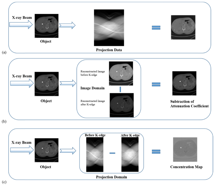
The rest of this paper is organized as follows. In Section 2, we give a detailed description for the proposed method for reconstruction of the contrast agent distribution from photon-counting data. In Section 3, we perform comprehensive numerical simulations to demonstrate the feasibility and accuracy of our proposed algorithm, relative to the results obtained using conventional CT and K-edge subtraction methods in the image domain, as shown in Fig. 1 . Finally, we discuss relevant issues and make a conclusion.
Fig. 1.
Different reconstruction methods with K-edge contrast agents. (a) Conventional CT; (b) K-edge subtraction in the image domain; and (c) K-edge imaging in the projection domain.
2. Methodology
When X-ray photons interact with a high-Z contrast agent, X-ray photoelectric absorption would experience a sudden increase, resulting in a significant difference of the X-ray transmission intensities between the left and right energy windows of the K-edge respectively. Let and respectively express energy bins before and after the K-edge energy of a specific contrast agent, as shown in Fig. 2 . According to the Beer–Lambert law, the number of X-ray photons recorded in the energy bins of and can be respectively expressed as
| (1) |
| (2) |
where is the attenuation coefficient of a scanned object at the energy E, and is the number of photons at energy E emitted from an X-ray source.
Fig. 2.
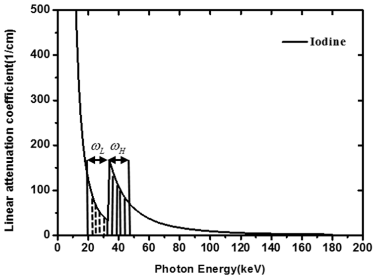
Energy window around the K-edge of Iodine.
The X-ray transmission intensity in the energy window before the K-edge would be much greater than in the energy window after the K-edge, because the attenuation coefficient in the energy window of is smaller than that in the energy window of . Using photon-counting detectors, the X-ray intensity data and respectively in the left and right windows of the K-edge can be simultaneously measured. Thus, we can use differential information of the intensities to reconstruct the contrast-agent distribution. Specifically, from Eqs. (1) and (2), we have
| (3) |
Although the attenuation coefficient is variable with respect to the X-ray energy, the attenuation coefficient is slow variation in such narrow energy bins of and near the K-edge. Hence, we can adopt the average value to approximate the attenuation coefficient in each energy bin:
| (4) |
where is the average attenuation coefficient distribution of the object in energy window of , and is the average attenuation coefficient distribution of the object in the energy window of .
By reorganizing Eq. (4), we obtain
| (5) |
In contrast-enhanced CT, the enhanced section is composed of contrast agents and human tissue. The total linear attenuation of a mixture matter is the sum of the contributions from the component materials, which means that the effective linear attenuation coefficient can be computed using the following formula:
| (6) |
where is the volume fraction of the contrast agent in the mixture matter, and are the linear attenuation coefficients of the contrast agent and tissue respectively.
From Eq. (6), we have
| (7) |
| (8) |
where is the average attenuation coefficient with the energy window before the K-edge jump and is the average attenuation coefficient with the energy window after the K-edge jump, and are the widths of energy windows and , respectively. An effective method has been presented to determine the optimal width of the left and right energy windows at K-edge [12]. Energy dependent attenuation coefficients of several kinds of contrast agents are available in the databases released by the National Institute of Standards and Technology [29].
Then, let us substitute Eqs. (7) and (8) into Eq. (5):
| (9) |
From Eq. (9), we obtain
| (10) |
Furthermore, Eq. (10) can be reduced to
| (11) |
Equation (11) is a general Radon transform to link the contrast-agent concentration to X-ray intensity measurement data. In practice, , , and in Eq. (11) are unknown. Here we present an iterative method to simultaneously reconstruct a contrast-agent distribution and tissue attenuation background and based on Eq. (11). More specifically, the image reconstruction process can be implemented iteratively as follows:
-
Step 1:Assume that and in Eq. (11) are equal. Thus, we have
(12) -
Step 2:
Reconstruct from measured K-edge imaging data based on Eq. (12). Image reconstruction of can be performed using conventional CT techniques, because the right-hand side of Eq. (12) is the weighted Radon transform of the contrast agent concentration map.
-
Step 3:
In the Eqs. (13) and (14), and are the measured X-ray intensity data, and and can be calculated from the reconstructed concentration and known attenuation coefficients of the contrast agent respectively. Hence, and can be reconstructed from Eqs. (13) and (14) respectively.
-
Step 4:
Substituting the reconstructed and into Eq. (11), we can further reconstruct the contrast agent concentration in the next iteration.
3. Numerical simulation
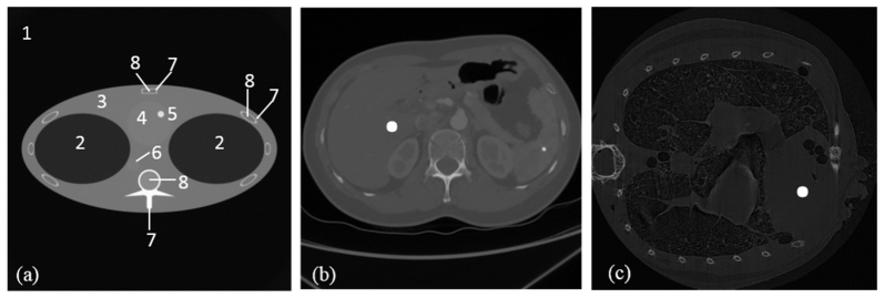
In this study, we designed three simulation tests to testify the proposed method. In those tests, the gadolinium solution was used as the contrast agents to analyze K-edge tomographic concentration imaging performance in a region of interest (ROI). In the first simulation, we used the FORBILD thorax phantom with a 1.5% gadolinium solution enhanced region in the heart area [30], as shown in Fig. 3(a)
Table 1. Material Type of the Phantom Sub Regions Shown In Fig. 3.
| Number | Material |
|---|---|
| 1 | air |
| 2 | lung |
| 3 | tissue |
| 4 | heart(blood) |
| 5 | ROI (1.5%Gadolinium + 98.5% Blood) |
| 6 | artery(blood) |
| 7 | bone |
| 8 | marrow |
. This phantom was of 40cm × 40cm with 1cm diameter enhanced ROI, as shown in Fig. 3. In this simulation, we used an industrial simulation environment for CT, called computer-assisted tomography simulation environment (CatSim) [31], which was developed by GE Global Research Center. CatSim incorporates polychromaticity, realistic quantum and electronic noise models, finite focal spot size and shape, finite detector cell size, detector cross-talk, detector lag or afterglow, bowtie filtration, finite detector efficiency, non-linear partial volume, scatter (variance-reduced Monte Carlo), and absorbed dose [31]. The CatSim simulation model is given by Eq. (15):
| (15) |
where is the detector signal with a sinogram index i, k is the energy index, s is the beam sub-sampling index, is the number of photons arriving at the detector without any attenuator in the energy bin indexed by k, is the intersection length between the line with an index s and an object with an index , is the linear attenuation coefficient of the object in the energy bin , is the scatter signal, computed by the Monte Carlo simulation, DQE is the detector quantum efficiency, is a factor to convert from keV to the number of electrons, and is the standard deviation of the electronic noise. Photon-counting detectors have the additional benefit of being less sensitive to electronic noise, which is done by using a threshold to discriminate charge pulses from the noise floor of the detector and associated electronics. While electronic noise will alter the energy attributed to a given X-ray photon, the number of counts is preserved and photon-counting detectors are expected to maintain better overall low-signal performance. We tested our reconstruction method in the CatSim simulation environment.
Fig. 3.
Numerical phantoms representative of real clinical and preclinical applications. (a) The FORBILD thorax phantom with a 1.5% Gadolinium solution enhanced region in the heart, where the sub region are defined in Table 1; (b) The human body phantom with a contrast enhancement region; (c) the mouse phantom with a contrast enhancement region of 0.1cm diameter.
For the second simulation, we designed human body phantoms adapted from a CT slice from a human body, which contained various ROIs of different sizes, as shown in Fig. 3(b). The phantom was discretized into a 512 × 512 matrix. One phantom includes a circular region with a diameter of 1.2 cm in the liver region, filled with tissue and gadolinium solution of 0.1%, 0.2%, and 0.5%. The other phantom includes a circular region with a diameter of 2 cm in the liver region, filled with tissue and gadolinium solution of 0.1%, 0.2%, and 0.5%, as shown in Fig. 3.
In the third simulation test, a mouse phantom was adapted from a micro-CT scan. The phantom includes a circular region with a diameter of 0.1 cm in the heart region, which is filled with tissue and iodine solution of 1.5%, as shown in Fig. 3(c). The iodine solution was used as the contrast agent to evaluate K-edge tomographic reconstruction for preclinical applications.
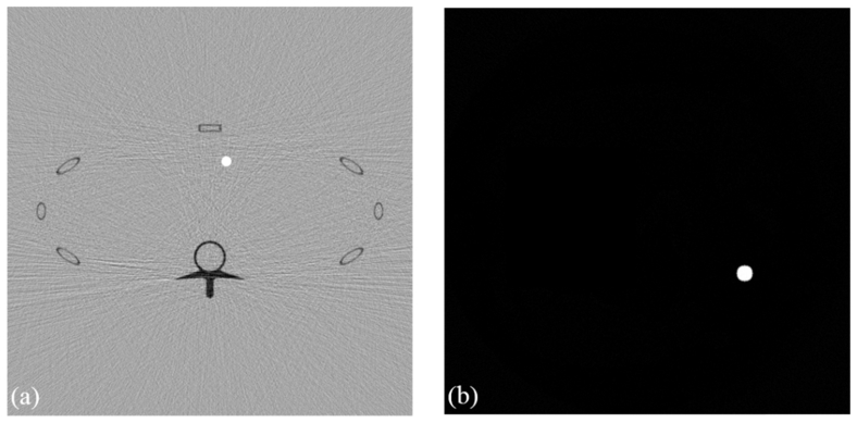
In the first and third simulations, the concentration map of contrast agents was reconstructed using our method as shown in Fig. 4 . We adopted two energy bins for the FORBILD phantom with 1.5% gadolinium solution: 45–50 keV and 50–55 keV respectively. The assessment was also done for the mouse phantom with 1.5% iodine solution, using energy bins of 29–33 keV and 33–37 keV. Figure 4 shows that our proposed method can provide quantitative distributions of the contrast agent tomographically and works well in the CatSim simulation environment, which is very close to real experiments and under preclinical conditions.
Fig. 4.
Contrast agent map. (a) The contrast agent map of the FORBILD thorax phantom with the display window [-5e-3, 5e-3], and (b) the contrast agent map of the mouse phantom with the display window [0, 15e-3].
To quantitatively evaluate the accuracy of reconstructed concentration distribution of contrast agent, we defined the average relative error (ARE) as:
| (16) |
where is the contrast-agent distribution in the reconstructed map, and is the contrast-agent distribution in the phantom. We calculated the average errors with different energy window widths (e.g., 1 to 30keV). Then, we selected the energy window width with the minimum ARE. To evaluate contrast resolution (CNR) [32], we define CNR as
| (17) |
where and are mean concentrations of the contrast agent and background regions, respectively, and is the standard deviation of the background in the reconstructed image.
3.1 Performance evaluation of reconstruction and iterative algorithm
We performed numerical simulation to test the convergence of our proposed iterative method. We designed a human body phantom adapted from a CT slice. The phantom contained a circular region with a diameter of 1.2cm in the liver region, filled with tissue and gadolinium solution of 0.1%. The phantom was discretized into a 512 × 512 matrix for numerical computation. We defined the difference between the current reconstructed and its previous value in the iterative process to test the convergence,
| (18) |
In every iterative step, we calculate the difference, and found that the difference is decreasing with the growth of iterative times, as shown in Fig. 5 . The error reaches its flat region with only six iterations, showing a good convergence of the iterative algorithm.
Fig. 5.
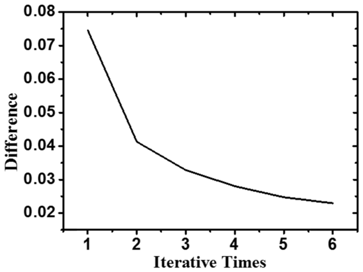
Difference Varied with Iterative Times.
Moreover, the reconstructed attenuation coefficient distribution of tissue with the proposed iterative algorithm is very close to the ground truth as illustrated in Fig. 6 . The average errors before and after the K-edge are 0.0262 and 0.0205 respectively, with the error defined as:
| (19) |
where is estimated attenuation coefficient distribution of tissue, and is original attenuation coefficient distribution of tissue.
Fig. 6.
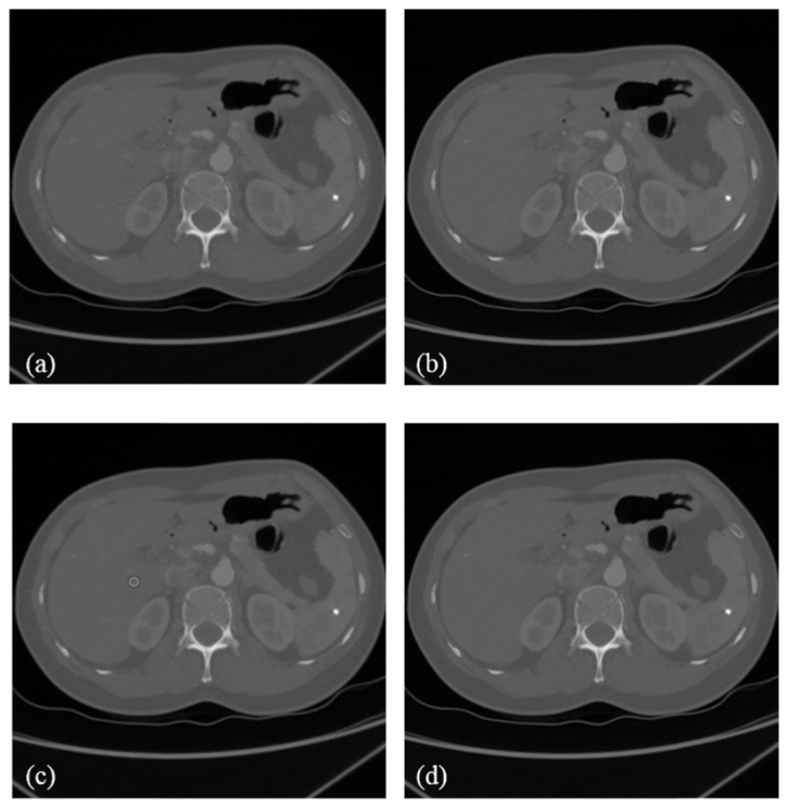
Attenuation coefficient distributions. (a) An estimated attenuation coefficient distribution before the K-edge. (b) The original attenuation coefficient distribution before the K-edge. (c) An estimated attenuation coefficient distribution after the K-edge. (d) The original attenuation coefficient distribution after the K-edge. The window display is [0, 3000] HU.
3.2 Comparative studies
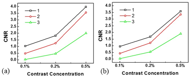
In this work, we proposed a method for K-edge imaging in the projection domain. GE Maxiray125 sources with a 140kV voltage spectrum and 100mA tube current were assumed in the simulation, which were simulated using a free software program (SpectrumGUI). The tube was equipped with a 3.0mm Al filter [33]. The photon counting detector measured X-ray intensities in spectral windows around the K-edge. The detector efficiency was 90%. Each cross-section was discretized into a 512 × 512 matrix for image reconstruction. Parallel-beam projections were equi-angularly acquired over a range in every energy window. Each projection was covered by 512 detector cells. To perform K-edge imaging, the filtered back projection (FBP) method was used based on Eq. (11). Then, a numerical evaluation was performed with the human body phantom. First, we calculated ARE under the conditions of different energy window widths, contrast concentrations and ROI sizes, using our method for K-edge imaging in the projection domain. Then, we selected the energy widow width with the minimum ARE to generate its CNR accordingly, as shown in Fig. 7 . We evaluate the results from visual inspection and quantitative measurement as follows:
Fig. 7.
CNR comparison study. (a) Comparison of the three methods in the 1.2 cm ROI with different concentrations of the contrast agent. (b) Comparison of the same methods with the 2 cm ROI. Note that 1 represents K-edge imaging in the projection domain, 2 is for the image domain subtraction, and 3 is for conventional CT.
1) Visual inspection
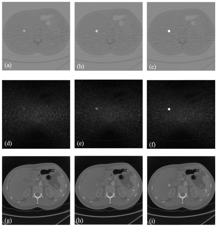
Figure 8 and Fig. 9 , show that (a)-(c) are the K-edge tomographic concentration images of the human body phantom with 0.1%, 0.2% and 0.5% gadolinium solution, (d) - (f) are the K-edge subtraction images of the human body phantom with 0.1%, 0.2% and 0.5% gadolinium solution, and (g) – (i) are the conventional CT reconstructed images of the human body phantom with 0.1%, 0.2% and 0.5% gadolinium solution respectively. The distribution of the contrast agent could only be recognized using K-edge imaging in the projection domain in the case of 0.1% concentration in Figs. 8 and 9. In the second and third columns of Figs. 8 and 9, the K-edge imaging method in the projection domain has a better visibility than the other two methods in the cases of 0.2% and 0.5% concentrations. Furthermore, the proposed method is quantitative in terms of the concentration of the contrast agent.
Fig. 8.
Study on the 1.2 cm ROI: (a)–(c) K-edge tomographic concentration images of the human phantom with 0.1%, 0.2%, and 0.5% gadolinium solution concentrations, respectively. (d)–(f) K-edge subtraction images of the human phantom with 0.1%, 0.2%, and 0.5% gadolinium solution concentrations, respectively. (g)–(i) Conventional CT images of the human phantom with 0.1%, 0.2%, and 0.5% gadolinium solution concentrations, respectively. The display windows are [-3e-3, 3e-3] for (a)–(c), [0, 1500] HU for (d)–(f), and [0, 2500] HU for (g)–(i).
Fig. 9.
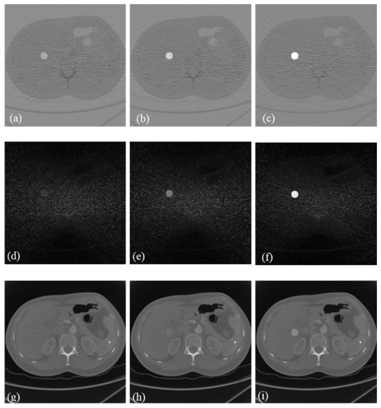
Study on the 2 cm ROI: (a)–(c) K-edge tomographic concentration images of the human phantom with 0.1%, 0.2%, and 0.5% gadolinium solution concentrations, respectively. (d)–(f) K-edge subtraction images of the human phantom with 0.1%, 0.2%, and 0.5% gadolinium solution concentrations, respectively. (g)–(i) Conventional CT images of the human phantom with 0.1%, 0.2%, and 0.5% gadolinium solution concentrations, respectively. The display windows are [-3e-3, 3e-3] for (a)–(c), [0, 1500] HU for (d)–(f), and [0, 2500] HU for (g)–(i).
2) Quantitative measurement
The results are summarized in Tables 2 and 3 . The data indicate that our proposed method has higher CNRs than the other two methods. When the contrast concentration was 0.1% in either the 1.2cm or 2cm ROI, the CNR with our method is 34.9 and 26.8 times higher than conventional CT, and 2.14 and 2.22 times higher than the image domain subtraction, respectively. When the concentration was 0.2% in these ROIs, the CNR of our method is 3.91 and 3.11 times higher than conventional CT, and 1.46 and 1.37 times higher than the image domain subtraction, respectively. When the concentration was increased to 0.5% in the ROIs, the CNR of our method is 1.99 and 1.89 times higher than conventional CT, and 1.12 and 1.07 times higher than the image domain subtraction, respectively. The CNR of an image increases with the square-root of radiation dose [34], which means that the proposed method can improve dose efficiency more than the two other methods. Figure 7 shows that with decreased contrast concentration, the capability of our proposed method is much better than the other two methods. The proposed method is both simple, sensitive and quantitative in the cases of low-contrast concentrations, which helps reduce dose of contrast agents in clinical applications.
Table 2. CNRs of Three Methods with 1.2cm ROI.
| Concentration | Conventional CT |
K-edge Subtraction Imaging (Image Domain) | K-edge Imaging (Projection Domain) | CNR Compared with Image Domain Subtraction | CNR Compared with Conventional CT |
|---|---|---|---|---|---|
| 0.1% | 0.0296 | 0.4832 | 1.032 | 2.14 | 34.9 |
| 0.2% | 0.4651 | 1.2479 | 1.8194 | 1.46 | 3.91 |
| 0.5% | 1.9994 | 3.5586 | 3.9775 | 1.12 | 1.99 |
Table 3. CNRs of Three Methods With 2cm ROI.
| Concentration | Conventional CT |
K-edge Subtraction Imaging (Image Domain) | K-edge Imaging (Projection Domain) | CNR Compared with Image Domain Subtraction | CNR Compared with Conventional CT |
|---|---|---|---|---|---|
| 0.1% | 0.0355 | 0.4277 | 0.9506 | 2.22 | 26.8 |
| 0.2% | 0.5379 | 1.2177 | 1.6732 | 1.37 | 3.11 |
| 0.5% | 1.9022 | 3.3491 | 3.5914 | 1.07 | 1.89 |
4. Discussions and conclusion
The existing methods for K-edge imaging rely on either projection decomposition or image subtraction [10,17]. As suggested in the introduction, the projection decomposition method can directly determine the distribution of a contrast agent, such as using a maximum likelihood method, which is a complex and time-consuming procedure. The image subtraction method first introduced by Jacobson [35] can remove the anatomical background, and enhance the contrast-agent distribution, which is effective in many biomedical applications. However, the main disadvantage of the subtraction technique is the increased dose, along with a possible image mis-registration. In contrast to these prior results, our method places an attention to use the signals from both sides of the K-edge based on the preserved partial volume assumption [36]. Dose efficiency is also an important matter in diagnostic X-ray imaging. In our numerical experiments, we have compared our method with two popular imaging methods for the evaluation of image quality, and the results show that our method can achieve higher contrast-to-noise ratio (CNR) and dose-efficiency than the two other methods. Also, our method only uses a single X-ray scan to acquire X-ray transmission data respectively in the left and right windows of the K-edge, and utilizes the difference of the measured intensity data across the K-edge to reconstruct a quantitative distribution of the contrast agent, allowing a reduced radiation dose.
In our phantom simulations, we have demonstrated the merits of the proposed method over the existing K-edge imaging methods. Our study differs from the previous methods because it implements K-edge imaging based on the preserved partial volume assumption and an associated closed-form solution. With the use of photon-counting detectors, the proposed method can reconstruct the contrast agent concentration distribution and the linear attenuation coefficients of tissue background simultaneously using a single K-edge scan. As shown in Figs. 7-9, the reconstruction of the distribution of a gadolinium contrast solution is highly accurate. Moreover, the computational cost of our method is much lower than the projection decomposition method.
In conclusion, a new iterative algorithm has been proposed to tomographically quantify a concentration distribution of a high-Z contrast agent from two measured transmission intensity data in the left and right energy windows of the K-edge based on the photon-counting detector. Our results have demonstrated that the proposed image reconstruction method can accurately quantify the distribution of contrast agent concentrations, and achieve optimal contrast-to-noise ratio at high computational and dose efficiencies. Clearly, the proposed method can be expanded to image multiple types of contrast agents, and has a great potential for dynamic contrast-enhanced cancer imaging and other applications.
Funding
National Institute of Health (NIH) ( R01EB016977, U01EB017140); National Hi-Tech Research and Development Program (NHRDP) ( 2015AA043203); National Natural Science Foundation Program of China (NSFPC) ( 61672099, 81430039, 61527827, 61501030, 61572076).
References and links
- 1.Udayasankar U. K., Li J., Baumgarten D. A., Small W. C., Kalra M. K., “Acute abdominal pain: value of non-contrast enhanced ultra-low-dose multi-detector row CT as a substitute for abdominal radiographs,” Emerg. Radiol. 16(1), 61–70 (2009). 10.1007/s10140-008-0743-0 [DOI] [PubMed] [Google Scholar]
- 2.Baldelli P., Bravin A., Di Maggio C., Gennaro G., Sarnelli A., Taibi A., Gambaccini M., “Evaluation of the minimum iodine concentration for contrast-enhanced subtraction mammography,” Phys. Med. Biol. 51(17), 4233–4251 (2006). 10.1088/0031-9155/51/17/008 [DOI] [PubMed] [Google Scholar]
- 3.Firsching M., Butler A. P., Scott N., Anderson N. G., Michel T., Anton G., “Contrast agent recognition in small animal CT using the Medipix2 detector,” Nucl. Instrum. Methods Phys. Res. 607(1), 179–182 (2009). 10.1016/j.nima.2009.03.141 [DOI] [Google Scholar]
- 4.Gierada D. S., Bae K. T., “Gadolinium as a CT contrast agent: Assessment in a porcine model,” Radiology 210(3), 829–834 (1999). 10.1148/radiology.210.3.r99mr06829 [DOI] [PubMed] [Google Scholar]
- 5.Xi Y., Tang R., Wang Y., Zhao J., “Microbubbles as contrast agent for in-line X-ray phase-contrast imaging,” Appl. Phys. Lett. 99(1), 011101 (2011). 10.1063/1.3607292 [DOI] [Google Scholar]
- 6.Carton A. K., Ullberg C., Lindman K., Acciavatti R., Francke T., Maidment A. D. A., “Optimization of a dual-energy contrast-enhanced technique for a photon-counting digital breast tomosynthesis system: I. A theoretical model,” Med. Phys. 37(11), 5896–5907 (2010). 10.1118/1.3490556 [DOI] [PMC free article] [PubMed] [Google Scholar]
- 7.Tanaka S., Sato N., Fujioka H., Takahashi Y., Kimura K., Iwamoto M., Uchiyama K., “Use of contrast-enhanced computed tomography in clinical staging of asymptomatic breast cancer patients to detect asymptomatic distant metastases,” Oncol. Lett. 3(4), 772–776 (2012). [DOI] [PMC free article] [PubMed] [Google Scholar]
- 8.Ghaghada K. B., Sato A. F., Starosolski Z. A., Berg J., Vail D. M., “Computed tomography imaging of solid tumors using a liposomal-Iodine contrast agent in companion dogs with naturally occurring cancer,” PLoS One 11(3), e0152718 (2016). 10.1371/journal.pone.0152718 [DOI] [PMC free article] [PubMed] [Google Scholar]
- 9.Alvarez R. E., Macovski A., “Energy-selective reconstructions in X-ray computerized tomography,” Phys. Med. Biol. 21(5), 733–744 (1976). 10.1088/0031-9155/21/5/002 [DOI] [PubMed] [Google Scholar]
- 10.Roessl E., Proksa R., “K-edge imaging in x-ray computed tomography using multi-bin photon counting detectors,” Phys. Med. Biol. 52(15), 4679–4696 (2007). 10.1088/0031-9155/52/15/020 [DOI] [PubMed] [Google Scholar]
- 11.Meng B., Cong W., Xi Y., Wang G., “Image reconstruction for X-ray K-edge imaging with photon counting detector,” Proc. SPIE 9212, 921219 (2014). 10.1117/12.2061392 [DOI] [Google Scholar]
- 12.Meng B., Cong W., Xi Y., De Man B., Wang G., “Energy window optimization for X-ray K-edge tomographic imaging,” IEEE Trans. Biomed. Eng. 63(8), 1623–1630 (2016). 10.1109/TBME.2015.2413816 [DOI] [PMC free article] [PubMed] [Google Scholar]
- 13.Heismann B., Leppert J., Stierstorfer K., “Density and atomic number measurements with spectral X-ray attenuation method,” J. Appl. Phys. 94(3), 2073–2079 (2003). 10.1063/1.1586963 [DOI] [Google Scholar]
- 14.Ballabriga R., Campbell M., Heijne E. H. M., Llopart X., Tlustos L., “The Medipix3 prototype, a pixel readout chip working in single photon counting mode with improved spectrometric performance,” IEEE Trans. Nucl. Sci. 54(5), 1824–1829 (2007). 10.1109/TNS.2007.906163 [DOI] [Google Scholar]
- 15.Iwanczyk J. S., Nygård E., Meirav O., Arenson J., Barber W. C., Hartsough N. E., Malakhov N., Wessel J. C., “Photon counting energy dispersive detector arrays for X-ray imaging,” IEEE Trans. Nucl. Sci. 56(3), 535–542 (2009). 10.1109/TNS.2009.2013709 [DOI] [PMC free article] [PubMed] [Google Scholar]
- 16.Yang Q., Cong W., Xi Y., Wang G., “Spectral X-ray CT image reconstruction with a combination of energy-integrating and photon-counting detectors,” PLoS One 11(5), e0155374 (2016). 10.1371/journal.pone.0155374 [DOI] [PMC free article] [PubMed] [Google Scholar]
- 17.Schlomka J. P., Roessl E., Dorscheid R., Dill S., Martens G., Istel T., Bäumer C., Herrmann C., Steadman R., Zeitler G., Livne A., Proksa R., “Experimental feasibility of multi-energy photon-counting K-edge imaging in pre-clinical computed tomography,” Phys. Med. Biol. 53(15), 4031–4047 (2008). 10.1088/0031-9155/53/15/002 [DOI] [PubMed] [Google Scholar]
- 18.Pani S., Saifuddin S. C., Ferreira F. I., Scuffham J. W., Stratmann P., Wilson M. D., Veale M. C., Bell S., Seller P., Sellin P. J., “Optimization of K-edge subtraction imaging using a pixellated spectroscopic detector,” in Proceedings of IEEE Conference on Nuclear Science Symposium and Medical Imaging (IEEE, 2012), pp. 3063–3066. 10.1109/NSSMIC.2012.6551700 [DOI] [Google Scholar]
- 19.Akiba K., Alozy J., Aoude R., van Beuzekom M., Buytaert J., Collins P., Suárez A. D., Dumps R., Gallas A., Hombach C., “Characterisation of Medipix3 silicon detectors in a charged-particle beam,” Physics (College Park Md.) 11(1), 262–265 (2016). [Google Scholar]
- 20.Ballabriga R., Campbell M., Heijne E., Llopart X., Tlustos L., Wong W., “Medipix3: A 64k pixel detector readout chip working in single photon counting mode with improved spectrometric performance,” Nucl. Instrum. Methods Phys. Res. 633(1), S15–S18 (2012). [Google Scholar]
- 21.Carramate L. F. N. D., Nachtrab F., Firsching M., Silva A. L. M., da Silva A. M., Veloso J. F. C. A., Uhlmann N., “Energy resolving CT systems using Medipix2 and MHSP detectors,” J. Instrum. 8(03), 101–109 (2013). 10.1088/1748-0221/8/03/C03022 [DOI] [Google Scholar]
- 22.Bones P. J., Butler A. P., Ronaldson J. P., Opie A. M., “Development of a CT scanner based on the Medipix family of detectors,” Proc. SPIE 7804, 780412 (2010). 10.1117/12.862166 [DOI] [Google Scholar]
- 23.Rubenstein E., Brown G. S., Harrison D. C., Hofstadter R., Hughes E. B., Kernoff R. S., Otis J. N., Thompson A. C., Zeman H. D., “Synchrotron radiation for transvenous coronary angiography,” Trans. Am. Clin. Climatol. Assoc. 97(1), 27–31 (1986). [PMC free article] [PubMed] [Google Scholar]
- 24.Lewin J. M., Isaacs P. K., Vance V., Larke F. J., “Dual-energy contrast-enhanced digital subtraction mammography: Feasibility,” Radiology 229(1), 261–268 (2003). 10.1148/radiol.2291021276 [DOI] [PubMed] [Google Scholar]
- 25.Peterzol A., Bravin A., Coan P., Elleaume H., “Performance of the K-edge digital subtraction angiography imaging system at the European synchrotron radiation facility,” Radiat. Prot. Dosimetry 117(1-3), 44–49 (2006). 10.1093/rpd/nci710 [DOI] [PubMed] [Google Scholar]
- 26.Schültke E., Fiedler S., Nemoz C., Ogieglo L., Kelly M. E., Crawford P., Esteve F., Brochard T., Renier M., Requardt H., Le Duc G., Juurlink B., Meguro K., “Synchrotron-based intra-venous K-edge digital subtraction angiography in a pig model: A feasibility study,” Eur. J. Radiol. 73(3), 677–681 (2010). 10.1016/j.ejrad.2009.01.019 [DOI] [PubMed] [Google Scholar]
- 27.Skarpathiotakis M., Yaffe M. J., Bloomquist A. K., Rico D., Muller S., Rick A., Jeunehomme F., “Development of contrast digital mammography,” Med. Phys. 29(10), 2419–2426 (2002). 10.1118/1.1510128 [DOI] [PubMed] [Google Scholar]
- 28.Lee Y., Lee A. C., Kim H.-J., “A Monte Carlo simulation study of an improved K-edge log-subtraction X-ray imaging using a photon counting CdTe detector,” Nucl. Instrum. Methods A. 830, 381–390 (2016). 10.1016/j.nima.2016.06.024 [DOI] [Google Scholar]
- 29.Hubbell J. H., “X-ray Mass Attenuation Coefficients”, http://www.nist.gov/pml/data/xraycoef/index.cfm.
- 30.Yu Z., Noo F., Dennerlein F., Wunderlich A., Lauritsch G., Hornegger J., “Simulation tools for two-dimensional experiments in X-ray computed tomography using the FORBILD head phantom,” Phys. Med. Biol. 57(13), N237–N252 (2012). 10.1088/0031-9155/57/13/N237 [DOI] [PMC free article] [PubMed] [Google Scholar]
- 31.Man B. D., Basu S., Chandra N., Dunham B., Edic P., Iatrou M., McOlash S., Sainath P., Shaughnessy C., Tower B., “CatSim: a new computer assisted tomography simulation environment,” Proc. SPIE 6510, 65102G (2007). [Google Scholar]
- 32.Cong W., Xi Y., Wang G., “X-ray fluorescence computed tomography with polycapillary focusing,” IEEE Access 2, 1138–1142 (2014). 10.1109/ACCESS.2014.2359831 [DOI] [Google Scholar]
- 33.Primak A. N., Ramirez Giraldo J. C., Liu X., Yu L., McCollough C. H., “Improved dual-energy material discrimination for dual-source CT by means of additional spectral filtration,” Med. Phys. 36(4), 1359–1369 (2009). 10.1118/1.3083567 [DOI] [PMC free article] [PubMed] [Google Scholar]
- 34.K. Iniewski, Integrated Microsystems: Electronics, Photonics, and Biotechnology (CRC Press, 2011). [Google Scholar]
- 35.Jacobson B., Mackay R. S., “Radiological contrast enhancing methods,” Adv. Biol. Med. Phys. 6(6), 201–261 (1958). [DOI] [PubMed] [Google Scholar]
- 36.Liu X., Yu L., Primak A. N., McCollough C. H., “Quantitative imaging of element composition and mass fraction using dual-energy CT: three-material decomposition,” Med. Phys. 36(5), 1602–1609 (2009). 10.1118/1.3097632 [DOI] [PMC free article] [PubMed] [Google Scholar]


