Abstract
Over one million total joint replacement surgeries were performed in the US in 2013 alone, and this number is expected to more than double by 2030. Traditional imaging techniques for post-operative evaluation of implanted devices, such as radiography, computerized tomography or ultrasound utilize ionizing radiation, suffer from beam hardening artifact, or lack the inherent high contrast necessary to adequately evaluate soft tissues around the implants, respectively. Magnetic resonance imaging (MRI), due to its ability to generate multi-planar, high contrast images without the use of ionizing radiation is ideal for evaluating peri-prosthetic soft tissues but has traditionally suffered from in-plane and through-plane data misregistration due to the magnetic susceptibility of implanted materials. A recent renaissance in the interest of imaging near arthroplasty and implanted orthopaedic hardware has led to the development of new techniques which help to mitigate the effects of magnetic susceptibility. This paper will describe the challenges of performing imaging near implanted orthopaedic hardware, how to generate clinically interpretable images when imaging near implanted devices, and how the images may be interpreted for clinical use. We will also describe current developments of utilizing MRI to evaluate implanted orthopaedic hardware.
Keywords: arthroplasty, metal, MRI, susceptibility
INTRODUCTION
Musculoskeletal disorders are responsible almost 10% of disability-adjusted life years globally, with osteoarthritis (OA) accounting for 10% (1) of this total. Osteoarthritis is the most common form of arthritis in the human body (2) and is the leading cause of disability in the United States, affecting 19% of adults, and is detected in a greater proportion of women (24.3%) than men (11.5%) (3). Total joint arthroplasty has been established as a clinically effective treatment for end-stage OA that results in pain reduction and improved patient quality of life. The Healthcare Utilization Project Nationwide Inpatient Sample has estimated that over 660,000 primary total knee arthroplasties (TKAs) and over 440,000 primary total hip arthroplasties (THAs) were performed in the US in 2013 alone (4); these numbers are expected to more than double by 2030 (5).
The popularity of TKA stems in large part from the high survivorship, with greater than 90% of the TKA knee implants being in place at ten years and beyond (6). Nonetheless, 15 to 30% of TKA patients remain unsatisfied (7), often beginning soon after surgery. Therefore, TKA is not achieving its goal of relieving pain and restoring function in a substantial portion of patients, and poor clinical outcomes represent a significant clinical concern for TKA. Similarly, THAs achieve excellent outcomes with traditional metal-on-polyethylene bearing materials with >80% survival at 20 years (8), but particulate debris from the ultrahigh molecular weight polyethylene (UHMWPE) component causes osteolysis and subsequent implant loosening (9,10). Alternative hard bearing surfaces, such as ceramics and metals have low wear rates (11,12), but have the disadvantages of implant chipping or fracture and squeaking (13), and wear debris particles generated from metal-on-metal articulations lead to premature failure of the THA (14,15), attributable to adverse local tissue reactions (ALTRs) in the soft tissues surrounding the THAs. Early detection of ALTRs or the presence of osteolysis and an expedited THA or TKA revision is crucial to achieve successful clinical outcome and minimize operative and rehabilitation costs.
Need for Imaging Near Arthroplasty
Standard radiography and computed tomography (CT) are commonly used to evaluate the presence of osteolysis, a leading cause of TKA failure (16,17), but the location, size, and number of lesions are frequently underestimated (18–21). Reported accuracy of radiographic identification of osteolysis ranges between 22% and 29% (19,20). The use of CT, reported as capable of detecting only 70% to 75% of simulated osteolytic lesions (21,22), exposes patients to ionizing radiation, a concern for longitudinal evaluation, and suffers from beam hardening artifact due to the presence of metallic components. Beam hardening may be mitigated by an increase of energy dose, but this also increases the radiation exposure. Even with these limitations, the American College of Radiology (ACR) considers CT to be an “appropriate” imaging modality following radiography for TKA patients experiencing pain and: 1) have a positive aspiration for infection or; 2) have a suspected infection, but with inconclusive aspiration culture or; 3) have a positive radiograph for loosening with negative aspiration for infection or; 4) have a negative radiograph for loosening and low probability for infection. PET/CT has been used to assess post-operative joint infection; however, it has a higher effective dose in adults (estimated: 10–30 mSv) as compared to CT (estimated: < 0.1 mSv), and is currently not approved for imaging inflammation and infection (23). Similarly for total hip arthroplasty, the utility of FDG-PET imaging is being evaluated and its role has not been fully assessed, and is graded as “usually not appropriate” for many clinical scenarios (24). Newer CT systems are capable of acquiring acquire dual-energy datasets (25) – the arthroplasty is imaged at two different kilovolt peaks, as compared to the conventional single peak (26), to reduce the effects of beam hardening artifact. In addition, iterative reconstruction techniques have been developed which may reduce artifacts in CT images with arthroplasty present (27). Even with these developments, radiography and CT lack the inherent soft tissue contrast necessary to evaluate the type and extent of synovitis around an implanted TKA. Three phase radioscintigraphy using methylene diphosphonate scanning can be used to evaluate for implant loosening, but suffers from poor soft tissue contrast, spatial resolution and specificity (28). Specific to THAs, a variety of imaging modalities have been used to visualize ALTRs, including radiography, CT, and ultrasound (29–32), but are limited by poor soft tissue contrast or variable penetration, respectively.
Magnetic resonance imaging (MRI) is a non-invasive imaging modality that permits multi-planar acquisition, provides high soft tissue contrast without the ionizing radiation needed for radiography or CT imaging. MRI also has higher accuracy in assessing peri-implant bone loss as compared to radiography and CT (21). A limitation of MRI following arthroplasty or orthopaedic hardware is magnetic susceptibility artifact, which may produce significant in-plane and through-plane misregistration (distortion) of the encoded signal, which obscures visualization of soft tissue and osseous detail. Understanding the source of artifact has allowed for the development of protocols and novel pulse sequences to enhance imaging of arthroplasty (33–38). We will describe the challenges of performing imaging near implanted orthopaedic hardware, how to generate clinically interpretable images when imaging near implanted devices, and how the images may be interpreted for clinical use. We will also describe the future of utilizing MRI to evaluate implanted orthopaedic hardware.
Imaging Near Metal in A Magnetic Field
Magnetic resonance imaging (MRI) utilizes a large external magnetic field, Bo, typically 1.5 Tesla (T) or 3T in clinically relevant systems, in combination with spatially varying magnetic gradients to localize apparent nuclear spin density, most notably protons in water and lipid molecules, within the tissue of interest and to generate image contrast in the anatomic structures. The spatial localization of the proton-dense human anatomy is dictated by the local precessional Larmor frequencies of the magnetic resonance visible protons in the prescribed field of view. Normally, the magnetic susceptibility (χ), or the tendency of a substance to become magnetized when exposed to an external magnetic field (39), of anatomic structures within a field of view are similar, resulting in locally similar precessional frequencies. Consequently, the linear relationship between precessional phase and spatial localization during data read out is maintained. The magnetic susceptibility of water and soft tissues is within the range of −7 to −11 parts-per-million (ppm) (40). However, the introduction of metallic materials such as those commonly used in orthopaedic surgery are significantly different than that of water in the human body: titanium (182 ppm (40)), cobalt chromium (1370 ppm (41)), and non-magnetic stainless steel (3520 to 6700 (40)). The larger magnetic susceptibility of these materials spatially alters the local Bo field and related Larmor frequency of nuclear spins. As a result, the linear relationship between precessional phase and spatial localization during data acquisition is no longer maintained. In addition, MR visible spins near boundaries of materials of mismatched susceptibilities leads to rapid intra-voxel dephasing of the spins and associated signal decay (42).
The effects of magnetic susceptibility artifact are commonly manifested in 3 forms: signal voids, voxel pileup, and distortion, the magnitude of which is proportional to the susceptibility differences between water and the offending material (43). Voxel pileup results from in-plane and through plane geometric shifting of signal from its original location to be superimposed with spins of similar frequencies, increasing the amplitude of the recorded signal. The shifting of the signal can create a signal void at the original geometric location if other displaced voxels do not map to the same geometric location. Signal voids can also be generated due to rapid phase coherence loss caused by local Bo variations within a single voxel. It should be noted that rapid dephasing of the spins may not always be considered a detriment in imaging, as superparamagnetic iron oxide (SPIO) and similar particles may be utilized to create negative contrast to localize liver tumors (44) or perform in vivo cell tracking (45). The theoretical in-plane displacement, or distortion, at any point of interest may be calculated by knowing the off-resonance frequency of the local spins:
| (Eq. 1) |
Where d is the calculated theoretical in-plane displacement, Δυ is the frequency offset (kHz), FOV is the in-plane field of view (mm), and RBW is the receiver bandwidth (kHz) (34). Similarly, the theoretical through-plane displacement may be calculated as:
| (Eq. 2) |
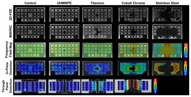
Where d is the calculated theoretical through-plane displacement, Δυ is the frequency offset at the point of interest (kHz), FOV is the in-plane field-of-view (mm), RBW is the receiver bandwidth (kHz), ST is the slice thickness (mm), and SBW is the slice-select bandwidth (kHz) (43). As an example, a total hip arthroplasty device composed of a cobalt-chromium alloy within the field of view will create off resonance effects of approximately 5kHz (43). Using imaging parameters recommended for in vivo 2D fast-spin-echo (FSE) imaging of THA (38) (field-of-view of 18cm, receiver bandwidth of ±100 kHz (390 Hz/pixel), excitation bandwidth of 1 kHz and slice thickness of 4 mm, one can anticipate an in-plane distortion of 4.5 mm, and associated through-plane distortion of 20.5 mm near the implanted metallic device. These theoretical calculations have been verified using a phantom designed to hold small cylindrical bars of known dimensions of common orthopaedic materials including ultra-high molecular weight polyethylene (UHMWPE), titanium alloy, chrome alloy, and stainless steel (43) (Figure 1). These results emphasize the presence of significant in-plane and through-plane distortion near orthopaedic hardware and the need to develop methodologies to minimize the artifacts. Fortunately, standard scanning hardware and software from all commercial vendors enable modification of product pulse sequences to reduce magnetic susceptibility artifact and render clinically interpretable images.
Figure 1.
2D-FSE (1st Row) and MAVRIC-SL (2nd Row) images of a polycarbonate grid phantom holding cylindrical bars (1.4 cm Ø) of ultra-molecular weight polyethylene (UHMWPE), titanium, cobalt chrome, stainless steel, or blank (control). Calculated in-plane (3rd Row) and through-plane (4th Row) distortions between the 2D-FSE and MAVRIC-SL scans display increasing distortions as the material magnetic susceptibility increases from UHMWPE to stainless steel. Significant distortion for stainless prevented calculation of through-plane distortions. Figure adapted from (43).
Means to Reduce Susceptibility in Standard Pulse Sequences
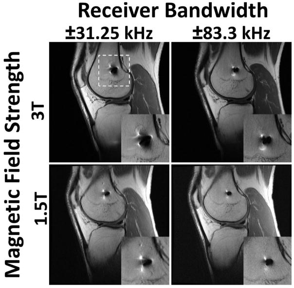
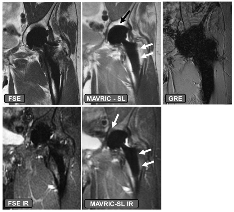
Modification of commercially available pulse sequences to reduce susceptibility artifacts may be understood using the context of the above mathematical relationships, and may be implemented without the need for a research protocol to be in place. As described above and elsewhere (34), image distortion is linearly related to the local frequency offset (Δυ), the specific series prescription (field of view and slice thickness) and the slice and receiver bandwidths. Additional modifications to parameters associated with image contrast may also be made to reduce artifacts. The magnitude of Δυ may be altered by selection of appropriate imaging field strength. Scanning using the clinical field strength of 1.5T instead of 3T is recommended, as susceptibility artifact is directly proportional to the magnetic field strength (15,46) (Figure 2). However, scanning at too low of a field strength (<1 T) may limit the available signal to noise. Constraining the magnitude of Δυ may also be altered in combination with a priori knowledge of the implant type. For example, orthopaedic materials with magnetic susceptibilities which do not affect the local Bo field, such as ultra-high molecular weight polyethylene (UHMWPE), will not locally distort images and will provide negative contrast in generated images (39). Implant components composed of non-plastic materials, such a ceramic-backed metal arthroplasty designs may also induce less distortion effects (Figure 3). Arthroplasties composed of titanium or oxidized zirconium will have less susceptibility artifact compared to cobalt-chromium alloy implants (47). Imaging at higher field strengths may not be precluded if the material is sufficiently far-field from the anatomy of interest and MR compatibility is satisfied. Distortion due to the material may also be reduced by aligning the implanted materials with Bo (48–50) or selection of materials with continuous, and not sharp, boundaries (48). However, hardware orientation or position may not be able to be modified due to its inherent location, such as a total shoulder replacement, or due to a patient’s habitus.
Figure 2.
The effects of altered receiver bandwidth and magnetic field strength on distortion artifact for a 32 year old male with anterior cruciate ligament reconstruction and a titanium interference screw in the femoral tunnel. White dashed lines indicate region of magnified inset. Image distortion is greatly amplified when acquiring images at a higher field strength (3T) and with a low receiver bandwidth (±31.25 kHz). Imaging at a lower field strength (1.5T) reduces susceptibility artifact, as does scanning with a higher receiver bandwidth (±83.3 kHz).
Figure 3.
The effects of implant material composition on susceptibility effect. A volunteer with a ceramic-on-polyethylene bearing total hip arthroplasty. The fast-spin-echo (FSE) and FSE inversion recovery (IR) images have higher susceptibility artifact present as compared to the MAVRIC SL and MAVRIC SL IR sequences, specifically at the dome of the acetabular component and along the stem of the femoral component (arrows). Utilizing a gradient recalled echo (GRE) acquisition, even with ceramic-on-polyethylene bearing surfaces leads to generation of non-diagnostic images.
Also present in the formulation are the effects of field-of-view and slice thickness. These factors, and the size of acquisition matrix by association, dictate the resulting size of the image voxel. Smaller voxels will reduce the local Bo variation within a voxel, reducing the intra-voxel spin dephasing and leading to greater signal available for image generation. As seen in Equation 2, increasing the receiver or slice selection bandwidths can reduce the magnitude of voxel encoding displacements (48). Altering the direction of the readout gradient will also change the direction of the artifact seen (50). We note, however, that an increase to receiver bandwidth will decrease the image signal-to-noise (SNR) ratio, but the reduction of SNR may be offset by the use of additional excitations.
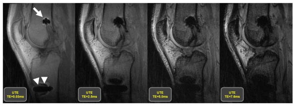
The above descriptions have focused on modifications of acquisition parameters, but the pulse sequence family is of great importance as well. Spin echo (SE) and Fast-spin-echo (FSE) imaging techniques are recommended for use rather than gradient recalled echo (GRE) imaging techniques (Figure 3), due to spin dephasing. Signal loss in GRE acquisitions may be reduced using the above techniques of alignment of the implanted device with Bo, decreasing echo times (Figure 4), and decreasing voxel size (51). Conventional single SE techniques have largely been replaced by more efficient interleaved fast-spin-echo (FSE) echo train techniques. FSE acquisitions using a large receiver bandwidth, and corresponding larger gradient amplitude to achieve the same voxel resolution, will acquire k-space data with greater speed, limiting the effects of intra-voxel dephasing. These increases will also result in a shorter inter-echo spacing during an FSE acquisition (52) such that a larger proportion of signal will be available for each data sample point and longer echo train lengths may be used to reduce overall scan time without significant degradation to image quality. We note, however, that an increase to receiver bandwidth will decrease the image signal-to-noise (SNR) ratio, but the reduction of SNR may be offset by the use of additional excitations. Most total joint imaging protocols rely on FSE pulse sequencing approaches to signal acquisition. Understanding the importance of the pulse sequence used and acquisition parameters, recommended protocols for imaging near TKAs and THAs are given in Tables 1 and 2, respectively. Suitable protocols for imaging of total shoulder replacements has been previously published (53).
Figure 4.
Images generated utilizing an ultra-short echo (UTE) acquisition, which is part of the GRE acquisition family, at 4 different echo times, of 32 year old man following an anterior cruciate ligament reconstruction with a titanium interference screw in the femoral tunnel (arrow) and a stainless steel button on the anterior aspect of the tibia (arrow heads) to secure the implanted graft. The images display that the use of longer echo times in a GRE acquisition results in a larger area of susceptibility artifact, which is minimized by the use of shorter echo times.
Table 1.
Suggested Protocol for Scanning to Total Knee Arthroplasty at 1.5T
| Pulse Sequence | |||||
|---|---|---|---|---|---|
| Parameters | Axial | Coronal | Sagittal | Sagittal | Sagittal |
| Acquisition Type | FSE | FSE | FSE | MAVRIC-SL | MAVRIC-SL |
| Weighting | Intermediate | Intermediate | Intermediate | Intermediate | STIR |
| Repetition Time (ms) | > 5000 | > 5000 | > 5000 | 4000–5000 | 4000–5000 |
| Echo Time (ms) | 30 | 30 | 30 | 40 | 40 |
| Fat Suppression | No | No | No | No | Inversion pulse at 150 ms |
| Echo Train Length | 16–24 | 16–24 | 16–24 | 24 | 24 |
| Receiver Bandwidth (Hz/pixel) | 488.3 | 488.3 | 488.3 | 488.3 | 488.3 |
| Flip Angle (deg) | 90 | 90 | 90 | 90 | 90 |
| Field of View (cm) | 16 × 16 | 16 × 16 | 20 × 20 | 20 × 20 | 20 × 20 |
| Acquisition Matrix | 512 × 320 | 512 × 320 | 512 × 320 | 512 × 256 | 512 × 256 |
| Slice Thickness (mm) | 3 | 4 | 2.5 | 3.6 | 3.6 |
| Section Gap (mm) | 0 | 0 | 0 | 0 | 0 |
| No. Signals Acquired | 4 | 4 | 4 | Variable | Variable |
| In-plane Frequency Direction | A to P | R to L | A to P | S to I | S to I |
| Acquisition Time | 5–8 mins | 5–8 mins | 5–8 mins | 5–7 mins | 5–7 mins |
Notes: A = Anterior, P = Posterior, R = Right, L = Left, S = Superior, I = Inferior
Table 2.
Suggested Protocol for Scanning to Total Hip Arthroplasty at 1.5T
| Pulse Sequence | ||||||
|---|---|---|---|---|---|---|
| Parameters | Axial | Axial | Coronal | Sagittal | Coronal | Coronal |
| Acquisition Type | FSE | FSE | FSE | FSE | MAVRIC-SL | MAVRIC-SL |
| Anatomy | Whole Pelvis | Hip Arthroplasty | Hip Arthroplasty | Hip Arthroplasty | Whole Pelvis | Whole Pelvis |
| Weighting | Intermediate | Intermediate | Intermediate | Intermediate | Intermediate | STIR |
| Repetition Time (ms) | 4000–5000 | 4000–5000 | 4000–5000 | 4000–5000 | 4000–5000 | 4000–5000 |
| Echo Time (ms) | 24–34 | 24–34 | 24–34 | 24–34 | 40 | 40 |
| Fat Suppression | No | No | No | No | No | Inversion pulse at 150 ms |
| Echo Train Length | 16–24 | 16–24 | 16–24 | 16–24 | 24 | 24 |
| Receiver Bandwidth (Hz/pixel) | 488.3 | 488.3 | 488.3 | 488.3 | 488.3 | 488.3 |
| Flip Angle (deg) | 90 | 90 | 90 | 90 | 90 | 90 |
| Field of View (cm) | 36 × 36 | 26 × 26 | 26 × 26 | 26 × 26 | 44 × 44 | 44 × 44 |
| Acquisition Matrix | 512 × 256 | 512 × 256 | 512 × 320 | 512 × 320 | 512 × 256 | 512 × 256 |
| Slice Thickness (mm) | 5 | 4 | 4 | 2.5 | 3.6 | 3.6 |
| Section Gap (mm) | 0 | 0 | 0 | 0 | 0 | 0 |
| No. Signals Acquired | 3 | 4–5 | 5 | 4 | Variable | Variable |
| In-plane Frequency Direction | S to I | S to I | R to L | A to P | S to I | S to I |
| Acquisition Time | 5–8 mins | 5–8 mins | 5–8 mins | 5–8 mins | 5–7 mins | 4–8 mins |
Notes: A = Anterior, P = Posterior, R = Right, L = Left, S = Superior, I = Inferior
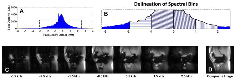
When metallic susceptibility effects are present within the imaging field of view, the techniques described above are frequently sufficient to generate clinically interpretable images. However, newer techniques have been developed to further suppress the effects of susceptibility artifact: Single Point Imaging (54,55), which uses only phase encoding to generate images; Projection Reconstruction (56–58), which can be used to acquire gradient-echo images with ultra-short echo times to minimize intra-voxel dephasing; and Prepolarized MRI which generates images in low Bo fields to reduce susceptibility (59,60), have been previously discussed (33). View angle tilting (VAT) imaging was originally proposed to correct geometrical shifts due to Bo inhomogeneities (61). When acquiring VAT images, a gradient is applied along the slice selection direction with an amplitude equal to the slice-selecting gradient to compensate for the Bo inhomogeneities. Although VAT minimizes in-plane artifacts, blurring may be evident, which may be corrected (62), and through plane artifacts are still present. The new multi-spectral imaging (MSI) techniques of multi-acquisition variable-resonance image combination (MAVRIC) (34), and slice encoding for metal artifact correction (SEMAC) (35) take advantage of the perturbed Bo field, and associated spin frequencies, to acquire datasets which minimize through-plane artifacts and mitigate in-plane artifacts. MAVRIC imaging generates numerous three-dimensional (3D) FSE image datasets at different acquisition frequency bands defined within the proton frequency spectrum (Figure 5), commonly within the range of ±12 k Hz (63). Scan time may be reduced by selective reduction of the number of frequency bins acquired (64) or utilizing parallel imaging. The individual spectral datasets are then combined using a sum of squares technique to generate a final output image (34). An initial limitation of MAVRIC was through-plane aliasing artifact due to the lack of slice selectivity (65). SEMAC minimizes in-plane distortion through the use of view angle tilt imaging (VAT) with additional phase encoding along the slice-select direction to minimize through plane distortion (35). As compared to MAVRIC, SEMAC generates lower SNR images (63), but a hybrid MAVRIC-SEMAC sequence (MAVRIC SL) has been developed which combines the high-resolution and high SNR images generated by MAVRIC with the slice location selectivity of SEMAC (63). The MAVRIC SL sequence has also been modified to obtain PD, T1weighted and short tau inversion-recovery images (66), while the SEMAC can acquire T2 weighted images, which has been shown to be beneficial when imaging around orthopaedic hardware in the spine (67) These MSI imaging techniques have been shown to be effective in increasing not only the visualization of capsular tissues in shoulder, knee, and hip arthroplasties, but also the presence of osteolysis at 1.5T (65). MSI techniques at 3T decrease image artifact and make capsular structures more discernable as compared to comparable 2D FSE images (68,69). These imaging techniques to reduce metallic susceptibility artifact are available from General Electric (MAVRIC-SL), Siemens (Advanced WARP) and Philips (OMAR).
Figure 5.
Schematic diagram of the multi-acquisition variable resonance image combination (MAVRIC) technique. The proton spectrum (A) is partitioned into separate frequency bins (B, 4 bins delineated) from which individual image datasets are created (C) at the specified frequency offsets. The data sets are then combined to generate a composite image (D).
Fat Suppression Imaging
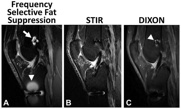
Generation of fat suppressed images near hardware is beneficial as implant loosening may display increased signal intensity at the metal-bone or cement-bone interface (70). A variety of different techniques are available when a water only image is desired. These techniques include:1) frequency selective fat suppression, commonly known as “fat-sat”; 2) spatial-spectral pulses (water-excitation); 3) short inversion time (TI) inversion recovery (STIR) imaging; 4) chemical shift based water – fat separation methods, such as Iterative Decomposition of Water and Fat With Echo Asymmetry and Least-Squares Estimation (IDEAL) (71); 5) fat suppression and balanced steady-state free precession (SSFP) sequences (72). The challenge of implementing many these techniques is due to the requirement of a locally homogeneous Bo field, which is disrupted by the presence of the locally different magnetic susceptibility of orthopaedic hardware. We note that other sources of magnetic susceptibility may include cosmetic materials such as dental fillings or dentures, as well as at air/tissue interfaces such the sinuses. Frequency selective fat suppression techniques (73) rely on the difference of precessional frequencies between protons associated with fat and water in the field of view, approximately 210 Hz at 1.5T and 420 Hz at 3T (72). If the local Bo is altered, the frequency differences will not be uniform across the anatomy being imaged, leading to non-uniform fat suppression (Figure 6). Similarly, spatial-spectral (water-excitation) pulse sequences suffer the same fate, as they assume the uniform frequency separation between water and fat species (74), leading to inconsistent fat suppression near metallic hardware. While not as severely affected as spectrally-selective fat suppression techniques, chemical shift based water–fat separation techniques, also known as “Dixon” techniques, also depend on phase differences between water and fat protons in the imaged volume and also tend to fail in the presence of orthopaedic hardware and Bo inhomogeneities due to the inability to predict and compensate for fat-water swaps near implants. Finally, SSFP sequences suffer from significant banding artifacts due to Bo inhomogeneities near orthopaedic hardware. Based on our long experience of imaging near arthroplasty, we have found the most clinically useful technique to suppress fat in the presence orthopaedic hardware is STIR.
Figure 6.
Comparison of frequency selective (A), short tau inversion recovery (STIR) (B), and DIXON (C) fat suppression techniques in a 32 year old male subject with an anterior cruciate ligament reconstruction and a titanium interference screw in the femoral tunnel (arrow) and a stainless steel button on the anterior aspect of the tibia (arrow head) to secure the implanted graft. The presence of metallic hardware generates local Bo inhomogeneities, causing local failure of frequency selective fat suppression techniques. STIR imaging has greater uniformity of fat suppression near the implanted hardware, with the reduction of image signal-to-noise ratio. Note the DIXON technique has slightly more artifact (arrowhead) than STIR but less than the frequency selective fat suppression.
STIR utilizes the differences in the T1 values between fat (T1=250 ms at1.5T) and water (T1=4000 ms at 1.5T) (75) to null the fat signal in generated images (Figure 6). In this technique, a 180 degree inversion RF pulse is applied to the local net magnetization, and voxels which are predominantly comprised of fat have faster longitudinal recovery back to equilibrium than voxels which are predominantly comprised of water. A 90 degree RF pulse is applied at the inversion time (TI) when the fat signal is zero (TI=140ms at 1.5T (76)) and data read out is performed to generate water only images. The selection of TI is dependent upon field strength (77,78) being used. This technique may be applied to tissues other than fat by selecting an appropriate inversion time: TI=T1*log(2)(79). A benefit of STIR imaging is the lack of dependence on local spin precession frequency, which is altered in the presence of hardware or the need for homogeneity of RF excitation pulses (B1 field), leading to homogenous fat suppression even in the presence of substantial orthopaedic hardware like arthroplasty. STIR imaging may also be applied to a large field of view or in joints unable to be positioned at isocenter; e.g., shoulders, without detrimental effects. Limitations of STIR imaging include potentially long imaging times due to longer TRs needed to achieve full T1 recovery prior to following excitations, a higher specific absorption rate (SAR) in imaged tissues from the 180° RF inversion pulses, lower SNR images due to reduced starting signal available prior to readout as compared to other imaging techniques, and the possibility of tissues other than fat may be nulled in generated images based on the non-fat specificity of the selected inversion time. Even with these limitations, STIR imaging is the optimal method for imaging near arthroplasty.
Clinical Imaging of Arthroplasty
Utilization of the aforementioned parameter modifications and advanced imaging sequences allows acquisition of high quality diagnostic MR images in patients with metallic implants on a routine clinical basis. This is particularly useful for detection of periprosthetic pathology in patients with suspected complications following joint arthroplasty, given the modality’s combination of superior tissue contrast, high spatial resolution, and sensitivity for mobile water. Knowledge of the expected normal postoperative appearance in patients with joint arthroplasties aids the interpreting radiologist in detection of abnormal findings, as does a detailed knowledge of pathologic conditions commonly encountered in the periprosthetic region. Certain conditions, such as component loosening, may be encountered in all types of arthroplasties, while other conditions, such as metallosis, are characteristically associated with certain arthroplasty bearings.
Arthroplasty Complications
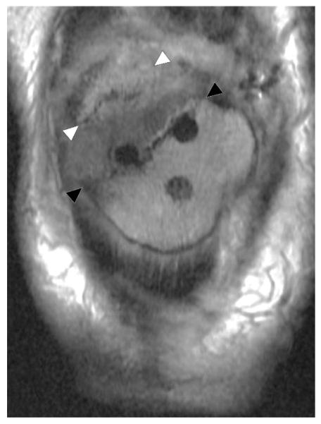
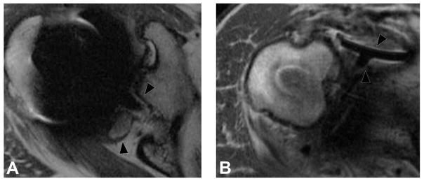
Complications which may be seen in association with all types of arthroplasties include periprosthetic fracture, mechanical loosening, polymeric wear/osteolysis, infection, malposition, instability, and hemarthrosis. Periprosthetic fracture may occur intraoperatively or at any point thereafter. Nondisplaced fractures are often radiographically subtle or may not be symptomatic, in which case MRI becomes particularly useful for diagnosis, given its sensitivity for associated marrow edema (38,80) (Figure 7). Mechanical component loosening is typically evident on MRI prior to becoming apparent on radiographs. The key imaging finding is a thin circumferential region of fibrous membrane formation - a synovialized linear gap with a fibrous interface along the bone-metal, bone-cement, or cement-metal junction. Ancillary findings may include marrow edema related to superimposed stress reaction, and advanced loosening may progress to component subsidence, angulation, and frank displacement (38,80) (Figure 8). Future directions of using MRI include the assessment of bone integration at the arthroplasty bone interface, both below and above the level of porous coating, which is typically present in the proximal third of a femoral stem. The high signal intensity afforded by fatty marrow provides a sharp contrast interface between the signal void of the metallic components and the surrounding trabecular bone. The tomographic nature of MR provides comprehensive evaluation of the implant interface and a mechanism by which to assess for longitudinal extent of osteo-integration, the presence of intervening fibrous membrane formation, and potential component loosening.
Figure 7.
Coronal FSE image (TE/TR = 27ms/3800ms) through the patella in a 65 year-old woman status post total knee arthroplasty demonstrates obliquely oriented periprosthetic fracture line (black arrowheads) through the resurfaced patella extending along the superior pegs, with superior retraction of the proximal fracture fragment (white arrowheads).
Figure 8.
Axial FSE PD image (A, TE/TR = 35ms/5833ms) in a 63 year-old man, status post total shoulder arthroplasty, demonstrate circumferential osseous resorption about the glenoid component, consistent with component loosening. Axial FSE PD image (B) in a 67 year-old woman following total shoulder arthroplasty demonstrates displacement of the glenoid component (black arrowheads).
Polymeric wear (“particle disease”) results in a classic synovitis characterized by fluid mixed with intermediate signal intensity polymeric debris (Figure 9). Osteolysis is often a feature of polymeric wear, resulting in well circumscribed lobular areas of osseous resorption, typically of intermediate signal intensity (Figure 10). Osteolysis may become quite bulky and extensive without causing component loosening, though loosening will occur if osteolysis circumferentially invests a component (80).
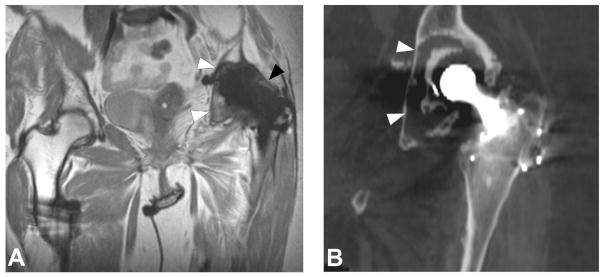
Figure 9.
Coronal MAVRIC PD (A, TE/TR = 42ms/4000ms) image in a 66 year-old woman status post total hip arthroplasty demonstrates synovial expansion with prominent intermediate signal intensity debris (black arrowheads) eroding into the periacetabular region, yielding circumferential osteolysis (white arrowheads) and acetabular component loosening, as also appreciated on corresponding coronally reformatted CT (B, white arrowheads).
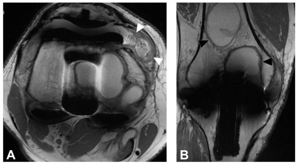
Figure 10.
Axial FSE image (A, TE/TR = 27ms/5150ms) in a 68 year-old man status post total knee arthroplasty demonstrates synovitis with intermediate signal intensity particulate debris (white arrowheads) consistent with polymeric wear. Coronal FSE image (B, TE/TR = 27ms/4017ms) demonstrates well circumscribed foci of osseous resorption (black arrowheads), consistent with osteolysis; while osteolysis associated with polymeric wear is classically isointense in signal, cystic osteolysis, as seen in this example, may also occur.
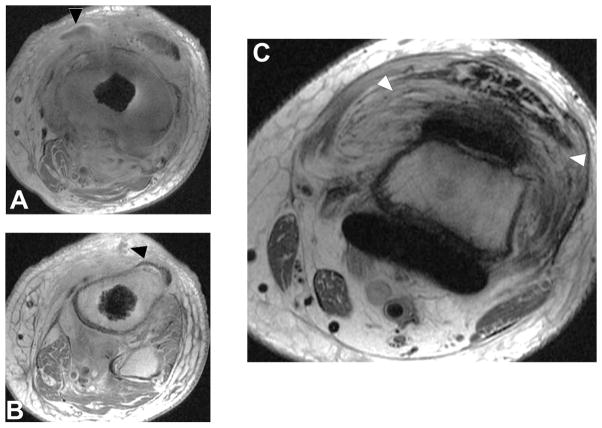
Infection is a dreaded complication in patients with joint arthroplasty, typically necessitating staged intervention, with removal of hardware, placement of a cement spacer and antibiotic therapy, and finally revision arthroplasty once all signs of active infection have completely resolved. On MRI, an infected joint arthroplasty generally manifests as a florid inflammatory synovitis with a characteristic hyperintense, thickened, and lamellated appearance surrounded by soft tissue edema (81) (Figure 11). Ancillary findings may include lymphadenopathy, fluid collections, and sinus tracts (38). Contrast is typically not necessary for the primary diagnosis of infection, but may be useful to define the fluid collections and sinus tracts (80). Post-contrast imaging, however, should not employ spectrally selective fat suppression, as this technique, as previously mentioned, fails in the presence of metallic hardware.
Figure 11.
T1 post contrast axial images (A, B, TE/TR = 12ms/582ms) in a 66 year-old man status post total knee arthroplasty demonstrate soft tissue fluid collection extending to the underlying bone (A, black arrowhead) which also communicates with the skin surface via a sinus tract (B, black arrowhead). Axial FSE image (C, TE/TR=30ms/6015ms) demonstrates severe inflammatory synovitis with a hyperintense lamellated appearance (white arrowheads), consistent with infection.
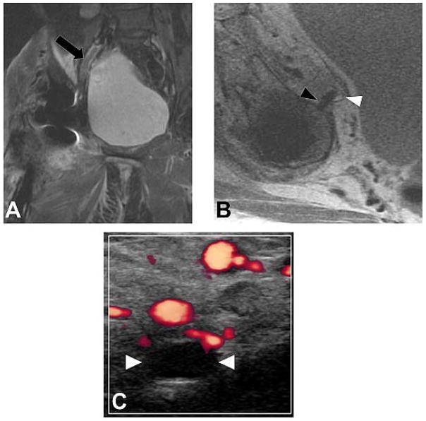
Component malposition may manifest as an early or late complication, while component failure tends to occur later in the postoperative course. Malpositioned components such as fixation screws may result in soft tissue or neurovascular impingement, thereby often becoming clinically evident within the early postoperative period (Figure 12). Subtle malalignment or malrotation of components may predispose the joint to dislocation and/or abnormal edge loading resulting in early component wear. Fracture of large metallic components is rare but not unheard of. More commonly, however, failure occurs as fracture of fixation screws, and breakage or displacement of polyethylene liners (80).
Figure 12.
Coronal IR (A, TE/TR=19ms/5175ms) and axial PD (B, TE/TR=35ms/2005ms) images in a 57 year-old woman status post total hip arthroplasty demonstrates proud acetabular fixation screw (black arrowhead) impinging the common iliac vein (white arrowhead), with associated deep venous thrombosis (black arrow), which was confirmed on subsequent Doppler ultrasound (C), which demonstrates lack of power Doppler flow within the common femoral vein (white arrowheads); thrombus was found to extend both proximally and distally.
Factors which may contribute to joint instability and dislocation in patients with arthroplasties include component malalignment and insufficiency of periarticular soft tissue stabilizers. For example, Lewinnek et al. established a “safe zone” of acetabular cup anteversion and inclination in hip arthroplasty, outside of which the articulation is at increased risk for dislocation (82). Deficiency of soft tissue stabilizers, such as the capsule and short external rotator tendons, predispose the joint to instability, and may necessitate the placement of a constrained construct in order to prevent dislocation (36). In a classic posterior surgical approach, the short external rotators tendons are released and subsequently repaired. Longitudinal analysis of this repair technique using MRI has shown that the piriformis and conjoined tendons form hypointense scar that aligns along the long axis of the original tendon, preventing clinical instability despite early failure of the repair (83,84)
Recurrent hemarthrosis may occur in patients following arthroplasty due to hyperemic, friable synovium and/or areas of synovial impingement. On MRI, hemarthrosis appears as a complex synovitis with bulky intermediate signal intensity deposits. Magnetic resonance angiography (MRA) may be helpful to localize a bleeding site and identify a candidate vessel suitable for image guided vascular embolization (37,38)
Joint Construct-Specific Complications
Certain complications may be characteristically associated with specific types of implants. For example adverse local tissue reactions (ALTRs), including ALVAL (aseptic lymphocytic vasculitis associated lesion) and metallosis, are typically observed in patients with hip arthroplasties incorporating a metal on metal bearing construct. ALTR is an umbrella term encompassing a variety of immune mediated reactions to metal wear debris in patients with hip arthroplasties, commonly those incorporating a metal on metal bearing, though an identical reaction may occur due to tribocorrosion at modular junctions. The type and severity of reaction is mediated by an interaction between host immune response with the type and volume of wear debris (85,86).
In patients with an immune predisposition, metal debris and corrosion products may provoke an aggressive type IV lymphocyte mediated hypersensitivity reaction which is known histopathologically as ALVAL (87). This process may result in aggressive and rapid periprosthetic soft tissue destruction, necessitating timely revision in order to minimize the degree of soft tissue damage at the time of revision surgery, as a greater degree of damage is associated with poorer outcomes following revision. MRI findings predict both the severity of the adverse reaction and the degree of soft tissue damage, thereby facilitating clinical decision making with regard to the necessity of revision (85,86). Imaging hallmarks of hypersensitivity type ALTRs include prominent synovial thickening, a mixed or solid synovitis, extra-articular decompression of synovitis, and soft tissue damage (Figure 13). Nawabi et al. devised an MRI based predictive model for ALTR/ALVAL in patients with metal on metal hip arthroplasties, reporting a 94% and 87% sensitivity and specificity, respectively, for predicting the presence of ALVAL at histology, and a 90% and 86% sensitivity and specificity, respectively, for predicting the degree of tissue damage observed intraoperatively at the time of revision surgery (85). This MRI based model outperformed blood metal ion levels as a predictor for ALVAL, which have a reported sensitivity and specificity of 63% and 86% respectively at an optimized cutoff value of 4.97 μg/L (88). In contrast to previously published MRI based morphologic grading systems (89–91), this predictive model was specifically devised to correlate with the histologic presence of ALVAL and to predict the degree of soft tissue damage encountered at the time of revision surgery.
Figure 13.
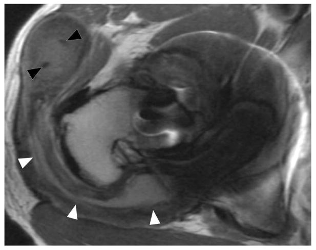
Axial FSE (TE/TR = 21ms/4283ms) in a 60 year-old woman status post resurfacing arthroplasty demonstrates decompression of an adverse local tissue reaction into the greater trochanteric bursa via a dehiscence in the posterior pseudocapsule (white arrowheads), with debris containing low signal intensity deposits (black arrowheads) located anteriorly within the bursa. ALVAL score at revision was 10 out of 10.
Metal debris and corrosion products may be present without provoking an aggressive hypersensitivity-type reaction in patients who are not immunologically predisposed to react in such a fashion. In these patients, deposition of metal wear debris may result in metallosis, a foreign body reaction which is typically much more indolent than the aforementioned ALVAL. At a cellular level, tissue macrophages phagocytize metal particles, as well as fusing to form foreign body giant cells in order to encapsulate large particles. This may lead to synovitis and a degree of tissue destruction, but tends not to be aggressive and rapidly progressive. Imaging characteristics associated with metallosis include mild synovitis without pronounced synovial thickening, low signal intensity deposits and osteolysis, and hypointense staining of the synovium (85,86) (Figure 14).
Figure 14.
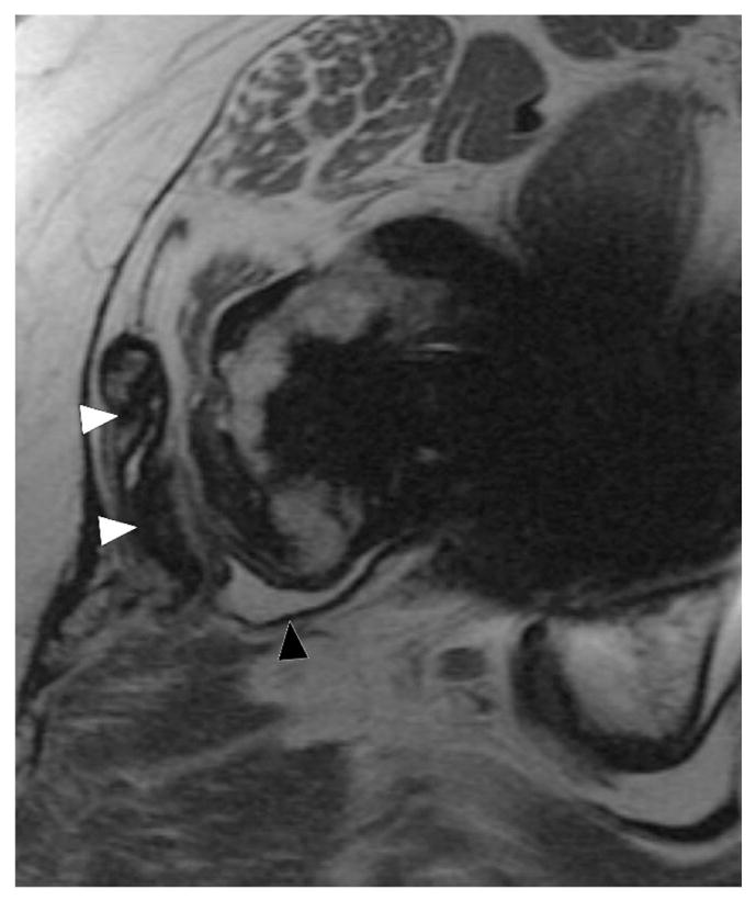
Axial FSE (TE/TR = 22ms/5217ms) in a 55 year-old woman status post total hip arthroplasty demonstrates decompression of synovitis into the greater trochanteric bursa via a dehiscence in the posterior pseudocapsule, with prominent low signal intensity debris (white arrowheads) located anteriorly within the bursa. In contrast to the previous case, note that the synovium is hypointense (black arrowhead), reflecting metal staining, without the marked thickening characteristic of a hypersensitivity-type ALTR.
While adverse local tissue reactions have been well described in metal on metal implants as well as modular metal or ceramic on polyethylene constructs, adverse synovial reactions can also occur unrelated to modularity and/or the presence of metal on metal bearings. By a process of trunnionosis, tribocorrosion can occur in which there is a mechanical shedding of debris at the trunnion, where the femoral stem meets the head, creating a direct inflammatory, cellular-mediated mechanism in which reactive oxygen species drive tissue necrosis, with a drop in regional tissue pH (92). This process results in a proliferative synovial process that results in regional necrosis of the surrounding muscle when the capsule is disrupted. Careful surveillance is necessary to detect these reactions prior to the spread of the inflammatory process into the surrounding soft tissue envelope. MRI thus serves as an effective means to monitor this process which can occur in the absence of clinical symptoms, in patients with seemingly well-functioning implants.
Heterotopic ossification may occur about any joint arthroplasty but extensive ossification is most commonly encountered about the hip. MRI is often obtained prior to resection of heterotopic ossification in order to delineate the relationship between the ossification and the periarticular soft tissues; particular care should be afforded to defining the proximity of heterotopic ossification to the neurovascular structures, in order to prevent hemorrhage and nerve damage during resection (38,80) (Figure 15).
Figure 15.
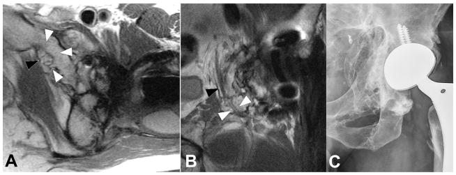
Axial (A, TE/TR = 25ms/5033ms) and coronal (B, TE/TR = 26ms/4000ms) FSE images, and radiograph (C), in a 33 year-old man status post total hip arthroplasty secondary to traumatic injury demonstrates encasement of the obturator nerve (black arrowheads) within an osseous tunnel (white arrowheads) formed by extensive heterotopic ossification, the extent of which is well appreciated on the concurrent radiograph.
Synovial scar formation is commonly observed in the peripatellar region in patients following knee arthroplasty, and may potentially result in complications such as mechanical impingement with locking and decreased range of motion. The classic example is “patellar clunk,” in which a scar nodule located along the superior aspect of the patella, which causes mechanical symptoms during range of motion, characteristically as the patient ranges from knee flexion to extension. MRI demonstrates a typically intermediate signal-intensity scar nodule in the characteristic location, while dynamic ultrasound may demonstrate impingement of the nodule during range of motion (37).
MRI may also be utilized to assess TKA component alignment, as malrotation between the femoral and tibial components has been implicated in pain related to a variety of resultant complications, including patellofemoral maltracking, ligament imbalance, polyethylene stress/failure, and overall abnormal joint kinematics. MR images are evaluated for the metrics of: femoral to tibial component rotation; tibial component to tibial tubercle axis; femoral component to surgical transepicondylar axis; and femoral component to clinical transepicondylar axis (37). These metrics from MR images are highly reproducible, and have been used to detect correlations between component malrotation and increased synovitis (93).
Scapular notching is a complication unique to reverse total shoulder arthroplasties, which are utilized in patients with rotator cuff pathology which often precludes their receiving a conventional shoulder arthroplasty. Notching results from repetitive impaction of the humeral polyethylene upon the inferior scapular neck, leading to focal loss of bone stock in this area. Predictors of scapular notching include surgical approach, preoperative diagnosis, glenoid wear, infraspinatus muscle quality, tilt of the glenosphere, and craniocaudal positioning (94). MRI can also evaluate the integrity of the rotator cuff in conventional shoulder arthroplasty, the presence of component loosening, and the degree of glenoid cartilage wear following hemiarthroplasty (53,65).
The 3D MSI techniques such as MAVRIC SL provide, for the first time, non-invasive direct visualization of the polyethylene on knee arthroplasties. Previous data have demonstrated the ability of MAVRIC to non-invasively distinguish different polyethylene designs and diagnose complications of polyethylene failure, such as fracture, displacement or backside wear (39). These data sets are amenable to 3D modeling, which may show a macroscopic visualization of polyethylene failure including disengagement from the locking mechanism on the tibial tray.
DISCUSSION
In conclusion, MRI has allowed, for the first time, a noninvasive means by which to comprehensively evaluate symptomatic joint arthroplasty, assessing for adverse tissue reactions with a greater sensitivity and specificity than any other imaging technique or blood test. These techniques may also be used to longitudinally follow patients with implants at risk, which is essential as many of these reactions occur in asymptomatic patients with seemingly well-functioning implants. Infection, malrotation and polymeric wear may be discerned, and future study will tomographically assess the bone implant integration.
Acknowledgments
Research reported in this publication was supported by National Institute of Arthritis and Musculoskeletal and Skin Diseases of the National Institutes of Health under award number R01AR064840.
The authors would like to thank Furhan Chodri and Dr. Ryan Breighner for their assistance in obtaining images for this manuscript.
References
- 1.Murray CJ, Vos T, Lozano R, et al. Disability-adjusted life years (DALYs) for 291 diseases and injuries in 21 regions, 1990–2010: a systematic analysis for the Global Burden of Disease Study 2010. Lancet. 2012;380:2197–2223. doi: 10.1016/S0140-6736(12)61689-4. [DOI] [PubMed] [Google Scholar]
- 2.Koopman WJ. Arthritis and Allied Conditions: A Textbook of Rheumatology. 13. Vol. 1. Williams & Wilkins; Baltimore: 1997. [Google Scholar]
- 3.Centers for Disease Control. Prevalence and most common causes of disability among adults—United States, 2005. Morbidity and Mortality Weekly Report. 2009;58:421–426. [PubMed] [Google Scholar]
- 4.Agency for Healthcare Research and Quality. [Accessed 29 Sept, 2016];HCUPnet, Healthcare Cost and Utilization Project. https://www.hcup-us.ahrq.gov/
- 5.Kurtz S, Ong K, Lau E, Mowat F, Halpern M. Projections of primary and revision hip and knee arthroplasty in the United States from 2005 to 2030. JBJS Am. 2007;89:780–785. doi: 10.2106/JBJS.F.00222. [DOI] [PubMed] [Google Scholar]
- 6.Font-Rodriguez DE, Scuderi GR, Insall JN. Survivorship of cemented total knee arthroplasty. CORR. 1997:79–86. [PubMed] [Google Scholar]
- 7.Noble PC, Conditt MA, Cook KF, Mathis KB. The John Insall Award: Patient expectations affect satisfaction with total knee arthroplasty. CORR. 2006;452:35–43. doi: 10.1097/01.blo.0000238825.63648.1e. [DOI] [PubMed] [Google Scholar]
- 8.Berry DJ, Harmsen WS, Cabanela ME, Morrey BF. Twenty-five-year survivorship of two thousand consecutive primary Charnley total hip replacements: factors affecting survivorship of acetabular and femoral components. JBJS Am. 2002;84-A:171–177. doi: 10.2106/00004623-200202000-00002. [DOI] [PubMed] [Google Scholar]
- 9.Willert HG, Semlitsch M. Reactions of the articular capsule to wear products of artificial joint prostheses. J Biomed Mater Res. 1977;11:157–164. doi: 10.1002/jbm.820110202. [DOI] [PubMed] [Google Scholar]
- 10.Holt G, Murnaghan C, Reilly J, Meek RM. The biology of aseptic osteolysis. CORR. 2007;460:240–252. doi: 10.1097/BLO.0b013e31804b4147. [DOI] [PubMed] [Google Scholar]
- 11.Hamadouche M, Boutin P, Daussange J, Bolander ME, Sedel L. Alumina-on-alumina total hip arthroplasty: a minimum 18.5-year follow-up study. JBJS Am. 2002;84-A:69–77. [PubMed] [Google Scholar]
- 12.Sieber HP, Rieker CB, Kottig P. Analysis of 118 second-generation metal-on-metal retrieved hip implants. JBJS Br. 1999;81:46–50. doi: 10.1302/0301-620x.81b1.9047. [DOI] [PubMed] [Google Scholar]
- 13.D’Antonio JA, Sutton K. Ceramic materials as bearing surfaces for total hip arthroplasty. J Am Acad Orthop Surg. 2009;17:63–68. [PubMed] [Google Scholar]
- 14.Jacobs JJ, Hallab NJ, Skipor AK, Urban RM. Metal degradation products: a cause for concern in metal-metal bearings? CORR. 2003:139–147. doi: 10.1097/01.blo.0000096810.78689.62. [DOI] [PubMed] [Google Scholar]
- 15.Farahani K, Sinha U, Sinha S, Chiu LC, Lufkin RB. Effect of field strength on susceptibility artifacts in magnetic resonance imaging. Comput Med Imaging Graph. 1990;14:409–413. doi: 10.1016/0895-6111(90)90040-i. [DOI] [PubMed] [Google Scholar]
- 16.Lombardi AV, Jr, Berend KR, Adams JB. Why knee replacements fail in 2013: patient, surgeon, or implant? Bone Joint J. 2014;96-B:101–104. doi: 10.1302/0301-620X.96B11.34350. [DOI] [PubMed] [Google Scholar]
- 17.Australian Orthopaedic Association National Joint Replacement Registry. [Accessed 1 Aug, 2016];Annual Report. 2014 https://aoanjrr.sahmri.com/annual-reports-2014.
- 18.Dalling JG, Math K, Scuderi GR. Evaluating the progression of osteolysis after total knee arthroplasty. J Am Acad Orthop Surg. 2015;23:173–180. doi: 10.5435/JAAOS-D-13-00189. [DOI] [PubMed] [Google Scholar]
- 19.Goldvasser D, Marchie A, Bragdon LK, Bragdon CR, Weidenhielm L, Malchau H. Incidence of osteolysis in total knee arthroplasty: comparison between radiographic and retrieval analysis. J Arthroplasty. 2013;28:201–206. doi: 10.1016/j.arth.2012.06.008. [DOI] [PubMed] [Google Scholar]
- 20.Lonner JH, Siliski JM, Scott RD. Prodromes of failure in total knee arthroplasty. J Arthroplasty. 1999;14:488–492. doi: 10.1016/s0883-5403(99)90106-7. [DOI] [PubMed] [Google Scholar]
- 21.Walde TA, Weiland DE, Leung SB, et al. Comparison of CT, MRI, and radiographs in assessing pelvic osteolysis: a cadaveric study. CORR. 2005;437:138–144. doi: 10.1097/01.blo.0000164028.14504.46. [DOI] [PubMed] [Google Scholar]
- 22.Kurmis TP, Kurmis AP, Campbell DG, Slavotinek JP. Pre-surgical radiologic identification of peri-prosthetic osteolytic lesions around TKRs: a pre-clinical investigation of diagnostic accuracy. J Orthop Surg Res. 2008;3:47. doi: 10.1186/1749-799X-3-47. [DOI] [PMC free article] [PubMed] [Google Scholar]
- 23.American College of Radiology. [Accessed 14 Nov, 2016];American College of Radiology ACR Appropriateness Critera for Imaging After Total Knee Arthroplasty. https://acsearch.acr.org/docs/69430/Narrative/
- 24.American College of Radiology. [Accessed 14 Nov, 2016];American College of Radiology ACR Appropriateness Critera for Imaging After Total Hip Arthroplasty. https://acsearch.acr.org/docs/3094200/Narrative/
- 25.Kaza RK, Platt JF, Cohan RH, Caoili EM, Al-Hawary MM, Wasnik A. Dual-energy CT with single- and dual-source scanners: current applications in evaluating the genitourinary tract. Radiographics. 2012;32:353–369. doi: 10.1148/rg.322115065. [DOI] [PubMed] [Google Scholar]
- 26.Pessis E, Campagna R, Sverzut JM, et al. Virtual monochromatic spectral imaging with fast kilovoltage switching: reduction of metal artifacts at CT. Radiographics. 2013;33:573–583. doi: 10.1148/rg.332125124. [DOI] [PubMed] [Google Scholar]
- 27.Morsbach F, Bickelhaupt S, Wanner GA, Krauss A, Schmidt B, Alkadhi H. Reduction of metal artifacts from hip prostheses on CT images of the pelvis: value of iterative reconstructions. Radiology. 2013;268:237–244. doi: 10.1148/radiol.13122089. [DOI] [PubMed] [Google Scholar]
- 28.Aliabadi P, Tumeh SS, Weissman BN, McNeil BJ. Cemented total hip prosthesis: radiographic and scintigraphic evaluation. Radiology. 1989;173:203–206. doi: 10.1148/radiology.173.1.2675184. [DOI] [PubMed] [Google Scholar]
- 29.Hart AJ, Sabah S, Henckel J, et al. The painful metal-on-metal hip resurfacing. JBJS Br. 2009;91:738–744. doi: 10.1302/0301-620X.91B6.21682. [DOI] [PubMed] [Google Scholar]
- 30.Heffernan EJ, Alkubaidan FO, Nielsen TO, Munk PL. The imaging appearances of metallosis. Skel Rad. 2008;37:59–62. doi: 10.1007/s00256-007-0362-y. [DOI] [PubMed] [Google Scholar]
- 31.Toms AP, Marshall TJ, Cahir J, et al. MRI of early symptomatic metal-on-metal total hip arthroplasty: a retrospective review of radiological findings in 20 hips. Clin Radiol. 2008;63:49–58. doi: 10.1016/j.crad.2007.07.012. [DOI] [PubMed] [Google Scholar]
- 32.Pandit H, Glyn-Jones S, McLardy-Smith P, et al. Pseudotumours associated with metal-on-metal hip resurfacings. JBJS Br. 2008;90:847–851. doi: 10.1302/0301-620X.90B7.20213. [DOI] [PubMed] [Google Scholar]
- 33.Koch KM, Hargreaves BA, Pauly KB, Chen W, Gold GE, King KF. MRI near metal implants. JMRI. 2010;32:773–787. doi: 10.1002/jmri.22313. [DOI] [PubMed] [Google Scholar]
- 34.Koch KM, Lorbiecki JE, Hinks RS, King KF. A multispectral three-dimensional acquisition technique for imaging near metal implants. Magn Reson Med. 2009;61:381–390. doi: 10.1002/mrm.21856. [DOI] [PubMed] [Google Scholar]
- 35.Lu W, Pauly KB, Gold GE, Pauly JM, Hargreaves BA. SEMAC: Slice Encoding for Metal Artifact Correction in MRI. Magn Reson Med. 2009;62:66–76. doi: 10.1002/mrm.21967. [DOI] [PMC free article] [PubMed] [Google Scholar]
- 36.Fritz J, Lurie B, Miller TT, Potter HG. MR imaging of hip arthroplasty implants. Radiographics. 2014;34:E106–132. doi: 10.1148/rg.344140010. [DOI] [PubMed] [Google Scholar]
- 37.Fritz J, Lurie B, Potter HG. MR Imaging of Knee Arthroplasty Implants. Radiographics. 2015;35:1483–1501. doi: 10.1148/rg.2015140216. [DOI] [PMC free article] [PubMed] [Google Scholar]
- 38.Hayter CL, Koff MF, Potter HG. MRI of the postoperative hip. JMRI. 2012;35:1013–1025. doi: 10.1002/jmri.23523. [DOI] [PubMed] [Google Scholar]
- 39.Li A, Sneag DB, Miller TT, Lipman JD, Padgett DE, Potter HG. MRI of Polyethylene Tibial Inserts in Total Knee Arthroplasty: Normal and Abnormal Appearances. AJR. 2016;206:1264–1271. doi: 10.2214/AJR.15.15107. [DOI] [PubMed] [Google Scholar]
- 40.Schenck JF. The role of magnetic susceptibility in magnetic resonance imaging: MRI magnetic compatibility of the first and second kinds. Med Phys. 1996;23:815–850. doi: 10.1118/1.597854. [DOI] [PubMed] [Google Scholar]
- 41.Bartusek K, Dokoupil Z, Gescheidtova E. Magnetic field mapping around metal implants using an asymmetric spin-echo MRI sequence. Measurement Science and Technology. 2006;17:3293. [Google Scholar]
- 42.White LM, Kim JK, Mehta M, et al. Complications of total hip arthroplasty: MR imaging-initial experience. Radiology. 2000;215:254–262. doi: 10.1148/radiology.215.1.r00ap11254. [DOI] [PubMed] [Google Scholar]
- 43.Koff MF, Shah P, Koch KM, Potter HG. Quantifying image distortion of orthopedic materials in magnetic resonance imaging. JMRI. 2013;38:1083–1091. doi: 10.1002/jmri.23991. [DOI] [PubMed] [Google Scholar]
- 44.Kuo YT, Chen CY, Liu GC, Wang YM. Development of Bifunctional Gadolinium-Labeled Superparamagnetic Nanoparticles (Gd-MnMEIO) for In Vivo MR Imaging of the Liver in an Animal Model. PLoS One. 2016;11:e0148695. doi: 10.1371/journal.pone.0148695. [DOI] [PMC free article] [PubMed] [Google Scholar]
- 45.Berner D, Brehm W, Gerlach K, et al. Longitudinal cell tracking and simultaneous monitoring of tissue regeneration after cell treatment of natural tendon disease by low-field magnetic resonance imaging. Stem Cells Int. 2016;2016:1207190. doi: 10.1155/2016/1207190. [DOI] [PMC free article] [PubMed] [Google Scholar]
- 46.Laakman RW, Kaufman B, Han JS, et al. MR imaging in patients with metallic implants. Radiology. 1985;157:711–714. doi: 10.1148/radiology.157.3.4059558. [DOI] [PubMed] [Google Scholar]
- 47.Ebraheim NA, Savolaine ER, Zeiss J, Jackson WT. Titanium hip implants for improved magnetic resonance and computed tomography examinations. CORR. 1992:194–198. [PubMed] [Google Scholar]
- 48.Tormanen J, Tervonen O, Koivula A, Junila J, Suramo I. Image technique optimization in MR imaging of a titanium alloy joint prosthesis. JMRI. 1996;6:805–811. doi: 10.1002/jmri.1880060515. [DOI] [PubMed] [Google Scholar]
- 49.Lee MJ, Kim S, Lee SA, et al. Overcoming artifacts from metallic orthopedic implants at high-field-strength MR imaging and multi-detector CT. Radiographics. 2007;27:791–803. doi: 10.1148/rg.273065087. [DOI] [PubMed] [Google Scholar]
- 50.Suh JS, Jeong EK, Shin KH, et al. Minimizing artifacts caused by metallic implants at MR imaging: experimental and clinical studies. AJR Am J Roentgenol. 1998;171:1207–1213. doi: 10.2214/ajr.171.5.9798849. [DOI] [PubMed] [Google Scholar]
- 51.Port JD, Pomper MG. Quantification and minimization of magnetic susceptibility artifacts on GRE images. J Comput Assist Tomogr. 2000;24:958–964. doi: 10.1097/00004728-200011000-00024. [DOI] [PubMed] [Google Scholar]
- 52.Eustace S, Jara H, Goldberg R, et al. A comparison of conventional spin-echo and turbo spin-echo imaging of soft tissues adjacent to orthopedic hardware. AJR Am J Roentgenol. 1998;170:455–458. doi: 10.2214/ajr.170.2.9456963. [DOI] [PubMed] [Google Scholar]
- 53.Sperling JW, Potter HG, Craig EV, Flatow E, Warren RF. Magnetic resonance imaging of painful shoulder arthroplasty. J Shoulder Elbow Surg. 2002;11:315–321. doi: 10.1067/mse.2002.124426. [DOI] [PubMed] [Google Scholar]
- 54.Gavira S, Cory DG. Sensitivity and resolution of constant-time imaging. J Magn Reson B. 1994;104:53–61. [Google Scholar]
- 55.Balcom BJ, Macgregor RP, Beyea SD, Green DP, Armstrong RL, Bremner TW. Single-Point Ramped Imaging with T1 Enhancement (SPRITE) J Magn Reson A. 1996;123:131–134. doi: 10.1006/jmra.1996.0225. [DOI] [PubMed] [Google Scholar]
- 56.Robson MD, Gatehouse PD, Bydder M, Bydder GM. Magnetic resonance: an introduction to ultrashort TE (UTE) imaging. J Comput Assist Tomogr. 2003;27:825–846. doi: 10.1097/00004728-200311000-00001. [DOI] [PubMed] [Google Scholar]
- 57.Idiyatullin D, Corum C, Park JY, Garwood M. Fast and quiet MRI using a swept radiofrequency. J Magn Reson. 2006;181:342–349. doi: 10.1016/j.jmr.2006.05.014. [DOI] [PubMed] [Google Scholar]
- 58.Barger AV, Block WF, Toropov Y, Grist TM, Mistretta CA. Time-resolved contrast-enhanced imaging with isotropic resolution and broad coverage using an undersampled 3D projection trajectory. Magn Reson Med. 2002;48:297–305. doi: 10.1002/mrm.10212. [DOI] [PubMed] [Google Scholar]
- 59.Macovski A, Conolly S. Novel approaches to low-cost MRI. Magn Reson Med. 1993;30:221–230. doi: 10.1002/mrm.1910300211. [DOI] [PubMed] [Google Scholar]
- 60.Venook RD, Matter NI, Ramachandran M, et al. Prepolarized magnetic resonance imaging around metal orthopedic implants. Magn Reson Med. 2006;56:177–186. doi: 10.1002/mrm.20927. [DOI] [PubMed] [Google Scholar]
- 61.Cho ZH, Kim DJ, Kim YK. Total inhomogeneity correction including chemical shifts and susceptibility by view angle tilting. Med Phys. 1988;15:7–11. doi: 10.1118/1.596162. [DOI] [PubMed] [Google Scholar]
- 62.Butts K, Pauly JM, Gold GE. Reduction of blurring in view angle tilting MRI. Magn Reson Med. 2005;53:418–424. doi: 10.1002/mrm.20375. [DOI] [PubMed] [Google Scholar]
- 63.Koch KM, Brau AC, Chen W, et al. Imaging near metal with a MAVRIC-SEMAC hybrid. Magn Reson Med. 2011;65:71–82. doi: 10.1002/mrm.22523. [DOI] [PubMed] [Google Scholar]
- 64.Kaushik SS, Marszalkowski C, Koch KM. External calibration of the spectral coverage for three-dimensional multispectral MRI. Magn Reson Med. 2016;76:1494–1503. doi: 10.1002/mrm.26065. [DOI] [PubMed] [Google Scholar]
- 65.Hayter CL, Koff MF, Shah P, Koch KM, Miller TT, Potter HG. MRI after arthroplasty: comparison of MAVRIC and conventional fast spin-echo techniques. Am J Roentgenol. 2011;197:W405–411. doi: 10.2214/AJR.11.6659. [DOI] [PubMed] [Google Scholar]
- 66.Koch KM, Koff MF, Shah PH, Kanwischer A, Gui D, Potter HG. Flexible longitudinal magnetization contrast in spectrally overlapped 3D-MSI metal artifact reduction sequences: Technical considerations and clinical impact. Magn Reson Med. 2015;74:1349–1355. doi: 10.1002/mrm.25518. [DOI] [PubMed] [Google Scholar]
- 67.Lee YH, Lim D, Kim E, Kim S, Song HT, Suh JS. Feasibility of fat-saturated T2-weighted magnetic resonance imaging with slice encoding for metal artifact correction (SEMAC) at 3T. Magn Reson Imaging. 2014;32:1001–1005. doi: 10.1016/j.mri.2014.04.009. [DOI] [PubMed] [Google Scholar]
- 68.Choi SJ, Koch KM, Hargreaves BA, Stevens KJ, Gold GE. Metal artifact reduction with MAVRIC SL at 3-T MRI in patients with hip arthroplasty. AJR Am J Roentgenol. 2015;204:140–147. doi: 10.2214/AJR.13.11785. [DOI] [PMC free article] [PubMed] [Google Scholar]
- 69.Kretzschmar M, Nardo L, Han MM, et al. Metal artefact suppression at 3 T MRI: comparison of MAVRIC-SL with conventional fast spin echo sequences in patients with Hip joint arthroplasty. Eur Radiol. 2015;25:2403–2411. doi: 10.1007/s00330-015-3628-0. [DOI] [PubMed] [Google Scholar]
- 70.Potter HG, Foo LF. Magnetic resonance imaging of joint arthroplasty. Orthop Clin North Am. 2006;37:361–373. doi: 10.1016/j.ocl.2006.03.003. [DOI] [PubMed] [Google Scholar]
- 71.Reeder SB, Pineda AR, Wen Z, et al. Iterative decomposition of water and fat with echo asymmetry and least-squares estimation (IDEAL): application with fast spin-echo imaging. Magn Reson Med. 2005;54:636–644. doi: 10.1002/mrm.20624. [DOI] [PubMed] [Google Scholar]
- 72.Bley TA, Wieben O, Francois CJ, Brittain JH, Reeder SB. Fat and water magnetic resonance imaging. JMRI. 2010;31:4–18. doi: 10.1002/jmri.21895. [DOI] [PubMed] [Google Scholar]
- 73.Haase A, Frahm J, Hanicke W, Matthaei D. 1H NMR chemical shift selective (CHESS) imaging. Phys Med Biol. 1985;30:341–344. doi: 10.1088/0031-9155/30/4/008. [DOI] [PubMed] [Google Scholar]
- 74.Block W, Pauly J, Kerr A, Nishimura D. Consistent fat suppression with compensated spectral-spatial pulses. Magn Reson Med. 1997;38:198–206. doi: 10.1002/mrm.1910380207. [DOI] [PubMed] [Google Scholar]
- 75.Bottomley PA, Foster TH, Argersinger RE, Pfeifer LM. A review of normal tissue hydrogen NMR relaxation times and relaxation mechanisms from 1–100 MHz: dependence on tissue type, NMR frequency, temperature, species, excision, and age. Med Phys. 1984;11:425–448. doi: 10.1118/1.595535. [DOI] [PubMed] [Google Scholar]
- 76.Smith RC, Constable RT, Reinhold C, McCauley T, Lange RC, McCarthy S. Fast spin echo STIR imaging. J Comput Assist Tomogr. 1994;18:209–213. doi: 10.1097/00004728-199403000-00007. [DOI] [PubMed] [Google Scholar]
- 77.Korb JP, Bryant RG. Magnetic field dependence of proton spin-lattice relaxation times. Magn Reson Med. 2002;48:21–26. doi: 10.1002/mrm.10185. [DOI] [PubMed] [Google Scholar]
- 78.Gold GE, Han E, Stainsby J, Wright G, Brittain J, Beaulieu C. Musculoskeletal MRI at 3. 0 T: relaxation times and image contrast. AJR Am J Roentgenol. 2004;183:343–351. doi: 10.2214/ajr.183.2.1830343. [DOI] [PubMed] [Google Scholar]
- 79.Del Grande F, Santini F, Herzka DA, et al. Fat-suppression techniques for 3-T MR imaging of the musculoskeletal system. Radiographics. 2014;34:217–233. doi: 10.1148/rg.341135130. [DOI] [PMC free article] [PubMed] [Google Scholar]
- 80.Burge AJ. Total hip arthroplasty: MR imaging of complications unrelated to metal wear. Semin Musculoskelet Radiol. 2015;19:31–39. doi: 10.1055/s-0034-1396765. [DOI] [PubMed] [Google Scholar]
- 81.Plodkowski AJ, Hayter CL, Miller TT, Nguyen JT, Potter HG. Lamellated hyperintense synovitis: potential MR imaging sign of an infected knee arthroplasty. Radiology. 2013;266:256–260. doi: 10.1148/radiol.12120042. [DOI] [PubMed] [Google Scholar]
- 82.Lewinnek GE, Lewis JL, Tarr R, Compere CL, Zimmerman JR. Dislocations after total hip-replacement arthroplasties. JBJS Am. 1978;60:217–220. [PubMed] [Google Scholar]
- 83.McLawhorn AS, Potter HG, Cross MB, et al. Posterior Soft Tissue Repair After Primary THA is Durable at Mid-term Followup: Prospective MRI Study. CORR. 2015;473:3183–3189. doi: 10.1007/s11999-015-4380-0. [DOI] [PMC free article] [PubMed] [Google Scholar]
- 84.Pellicci PM, Potter HG, Foo LF, Boettner F. MRI shows biologic restoration of posterior soft tissue repairs after THA. CORR. 2009;467:940–945. doi: 10.1007/s11999-008-0503-1. [DOI] [PMC free article] [PubMed] [Google Scholar]
- 85.Nawabi DH, Gold S, Lyman S, Fields K, Padgett DE, Potter HG. MRI predicts ALVAL and tissue damage in MOM hip arthroplasty. CORR. 2014;472:471–481. doi: 10.1007/s11999-013-2788-y. [DOI] [PMC free article] [PubMed] [Google Scholar]
- 86.Burge AJ, Gold SL, Lurie B, et al. MR Imaging of Adverse Local Tissue Reactions around Rejuvenate Modular Dual-Taper Stems. Radiology. 2015;277:142–150. doi: 10.1148/radiol.2015141967. [DOI] [PubMed] [Google Scholar]
- 87.Campbell P, Ebramzadeh E, Nelson S, Takamura K, De Smet K, Amstutz HC. Histological features of pseudotumor-like tissues from metal-on-metal hips. CORR. 2010;468:2321–2327. doi: 10.1007/s11999-010-1372-y. [DOI] [PMC free article] [PubMed] [Google Scholar]
- 88.Hart AJ, Sabah SA, Bandi AS, et al. Sensitivity and specificity of blood cobalt and chromium metal ions for predicting failure of metal-on-metal hip replacement. JBJS Br. 2011;93:1308–1313. doi: 10.1302/0301-620X.93B10.26249. [DOI] [PubMed] [Google Scholar]
- 89.Anderson H, Toms AP, Cahir JG, Goodwin RW, Wimhurst J, Nolan JF. Grading the severity of soft tissue changes associated with MOM hip replacements: reliability of an MR grading system. Skel Rad. 2011;40:303–307. doi: 10.1007/s00256-010-1000-7. [DOI] [PubMed] [Google Scholar]
- 90.Hauptfleisch J, Pandit H, Grammatopoulos G, Gill HS, Murray DW, Ostlere S. A MRI classification of periprosthetic soft tissue masses (pseudotumours) associated with metal-on-metal resurfacing hip arthroplasty. Skel Rad. 2012;41:149–155. doi: 10.1007/s00256-011-1329-6. [DOI] [PubMed] [Google Scholar]
- 91.Matthies AK, Skinner JA, Osmani H, Henckel J, Hart AJ. Pseudotumors are common in well-positioned low-wearing metal-on-metal hips. CORR. 2012;470:1895–1906. doi: 10.1007/s11999-011-2201-7. [DOI] [PMC free article] [PubMed] [Google Scholar]
- 92.Gilbert JL, Sivan S, Liu Y, Kocagoz SB, Arnholt CM, Kurtz SM. Direct in vivo inflammatory cell-induced corrosion of CoCrMo alloy orthopedic implant surfaces. J Biomed Mater Res A. 2015;103:211–223. doi: 10.1002/jbm.a.35165. [DOI] [PMC free article] [PubMed] [Google Scholar]
- 93.Murakami AM, Hash TW, Hepinstall MS, Lyman S, Nestor BJ, Potter HG. MRI evaluation of rotational alignment and synovitis in patients with pain after TKR. JBJS Br. 2012;94:1209–1215. doi: 10.1302/0301-620X.94B9.28489. [DOI] [PubMed] [Google Scholar]
- 94.Nicholson GP, Strauss EJ, Sherman SL. Scapular notching: Recognition and strategies to minimize clinical impact. CORR. 2011;469:2521–2530. doi: 10.1007/s11999-010-1720-y. [DOI] [PMC free article] [PubMed] [Google Scholar]


