Abstract
On-chip microparticle and cell coating technologies enable a myriad of applications in chemistry, engineering, and medicine. Current microfluidic coating technologies often rely on magnetic labeling and concurrent deflection of particles across laminar streams of chemicals. Herein, we introduce an acoustofluidic approach for microparticle and cell coating by implementing tilted-angle standing surface acoustic waves (taSSAWs) into microchannels with multiple inlets. The primary acoustic radiation force generated by the taSSAW field was exploited in order to migrate the particles across the microchannel through multiple laminar streams which contained the buffer and coating chemicals. We demonstrate effective coating of polystyrene microparticles and HeLa cells without the need for magnetic labelling. We characterized the coated particles and HeLa cells with fluorescence microscopy and scanning electron microscopy. Our acoustofluidicbased particle and cell coating method is label-free, biocompatible, and simple. It can be useful in the on-chip manufacturing of many functional particles and cells.
Graphic Content Entry
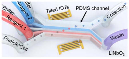
Herein, we have demonstrated coating of particles and cells utilizing the taSSAW approach.
Introduction
The ability to coat microparticles and living cells greatly benefits a wide range of applications, including biosensing,1,2 drug delivery,3,4 toxicity screening,5–8 and biochemical reactions.9–11 Conventional methods require multi-step washing and medium exchange processes to achieve multiple layers of coating. These processes are labor-intensive, risk the contamination of the samples, and increase the consumption of chemical reagents.12 Microfluidics enables the handling of extremely small volumes of liquids from nanoliters to picoliters in a confined environment which helps reduce the consumption of expensive reagents and prevents contamination of products.13–15 A simple microfluidic particle coating process involves continuously “dipping” particles into streams of multiple reagents and buffer solutions to achieve the desired coating and washing steps in a single device.16–18
Magnetic forces have been the most widely exploited method used to achieve sequential coating and washing of particles and cells in microfluidic devices.19,20 The basic scheme of magnetic-based approaches uses either intrinsically ferromagnetic particles or magnetic nanoparticle-incorporated living cells that are pulled by an externally applied magnetic field across laminar flows of multiple chemicals and washing buffers. However, the requirement of magnetism (i.e. ferromagnetic) limits this approach to specific particles and modified cells. Tarn et al. recently demonstrated diamagnetic repulsion of particles in paramagnetic solutions and ferrofluids.21 Exploiting the weak diamagnetism of most biological cells and polymer microparticles, they achieved fluorescent biotin coating and repulsion of polymer microparticles in a paramagnetic washing solution. Even though they used non-ferromagnetic particles, they still needed special washing media to generate sufficient repulsion of the intrinsically diamagnetic particles. Furthermore, this approach, in its current capacity, is only applicable to single-step reactions, and suggests the need for a more capable method.
A passive guiding method has also been demonstrated to generate layer-by-layer coated droplets using arrays of micropillars in polydimethylsiloxane (PDMS) microchannels.22 Similar hydrodynamic based medium exchange methods were also demonstrated using hydrodynamic filtration and size-selective guiding via slanted micro-obstacles.23,24 These approaches lack dynamic control and dexterity. Considering the immense potential of microfluidics in sample preparation and bioanalysis, there is still an unmet need for a simple, effective, and versatile on-chip particle/cell coating method.
Acoustofluidic (i.e. the fusion of acoustics and microfluidics) based particle and cell manipulation methods have been demonstrated in many lab-on-a-chip applications.25–40 For example, Li et al. used tilted angle standing surface acoustic waves to navigate white blood cells from lysed blood samples.41 After the cell washing process, the debris in the collection outlet decreased from ~22 % to ~2%. Hawkes et al. also reported continuous cell washing using ultrasound standing waves.42 Similarly, Petersson et al. and Augustsson et al. used ultrasonic standing wave focusing to exchange carrier medium of particles.30,43 However, to the best of our knowledge acoustic based particle/cell coating has not been demonstrated thus far.
In this study, we present an on-chip particle and cell coating method using tilted-angle standing surface acoustic waves (taSSAW).41,44–46 In particular, we demonstrate effective on-chip coating of poly(allylamine hydrochloride) (PAH) and poly(styrene sulfonate) (PSS)47–49 layers using taSSAW. We first achieved efficient translation of polystyrene microparticles along the tilted pressure nodes and across the microchannel while preserving the laminar characteristics of the incoming flows. Later, we demonstrated the capability of our device to achieve single- and double-layer coating of HeLa cells and polystyrene particles, respectively. Our acoustofluidic-based coating method provides well defined sequential transport of particles and cells across multiple fluid layers at relatively low acoustic powers. It is capable of coating particles and cells on-demand in a label-free, simple, biocompatible, and versatile manner. With these advantages, our method can be valuable in many applications such as particle functionalization, multilaminar binding assays, layer-by-layer coating, and bioanalysis.
Working Mechanism
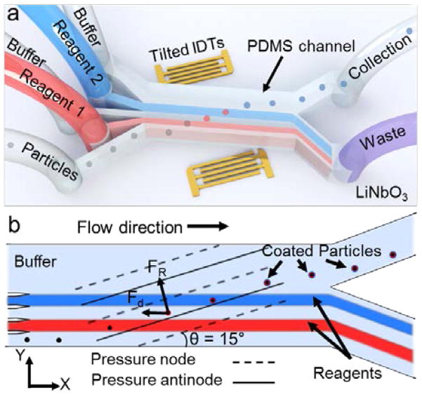
The taSSAW-based device (Fig. 1a) uses a PDMS micro-channel that is positioned between a pair of tilted interdigitated transducers (IDTs) patterned on a piezoelectric lithium niobate (LiNbO3) substrate. Once a radio frequency (RF) signal is applied to the pair of IDTs, the constructive interference of the two oppositely traveling surface acoustic waves creates standing surface acoustic waves (SSAWs) within the fluid medium inside the PDMS microchannel (Fig. 1b).50,51 The interference also forms pressure fluctuations in the fluid medium which develop into regions of minimum and maximum amplitudes; these are called the pressure nodes and antinodes, respectively. Particles that are present in this physical system are subject to a primary acoustic radiation force (FR): 52
Fig. 1.
Schematic and working principle of the taSSAW based particle-coating device. (a) 3D illustration of the five-inlet, two-outlet PDMS microchannel and tilted IDTs on lithium niobate (LiNbO3) substrate. Not to scale. (b) Particles entering the device from the bottom inlet are pushed to the pressure nodes by the acoustic radiation force. While the particles migrating across the microchannel, they are coated with the red stream, washed, coated with the blue stream, and leave the device in the final buffer stream.
| (1) |
| (2) |
where po and Vp are the acoustic pressure upon the particle and the volume of the particle, respectively; βf, βp, ρf, and ρm are the compressibility and density of the fluid and those of the particle, respectively; and ϕ, κ, λ, and x are the acoustic contrast factor, wavenumber, wavelength, and distance from a pressure node, respectively. The acoustic contrast factor determines the direction of FR which can be towards the pressure nodes or antinodes. For instance, if the density of the particle is greater than the density of the fluid medium, the particle is directed towards the pressure nodes. Recent work by Doinikov demonstrated that viscosity and viscous heat-conducting should be considered for more accurate quantitative and qualitative analyses.53,54 In general, considerable corrections are required for particles with densities significantly different than the medium.55 In addition to the primary acoustic radiation force, the particles moving with the flow in the microchannel also experience a Stokes drag force (Fd):
| (3) |
where η, Rp, up, and uf are fluid viscosity, radius of the particle, velocity of the particle, and velocity of the fluid, respectively. The motion of particles and cells in the SSAW field inside a microchannel can be described using these two forces. The magnitude of the acoustic radiation force (FR) is the primary factor retaining the particles in the nodal position along the tilt angle of the IDTs, which is the greatest contributor to the vertical deflection of the particles. The vertical deflection refers to the deflection of the particles/cells across the width of the microchannel in the y-direction (Fig. 1b). For example, bigger and denser particles in a high-frequency and high-power SSAW field experience a larger radiation force and vertical deflection. However, there are limitations on the adjustment of the system parameters such as acoustic power, which cannot be increased infinitely to maximize the vertical deflection due to the concurrent fluid mixing between different chemicals. Thus, there exists a balance between the fluidic and acoustic parameters. By adjusting the flow rates and acoustic power, an optimal performance can be achieved.
Owing to the tilted geometry of the IDTs and the resulting pressure nodes, particles/cells that are deflected by the acoustic radiation force along the pressure nodes of the taSSAWs are guided through the width of the microchannel. By maintaining the laminar flow profile, the deflected and guided particles/cells are sequentially submerged into various liquids by crossing through the streams of chemicals and washing buffer. As a result, the particles can be coated with multiple layers of chemicals (Fig. 1b).
Materials and Methods
Device design and fabrication
A PDMS microchannel with five inlets and two outlets was placed onto a LiNbO3 substrate patterned with a tilted pair of IDTs (Fig. 1a, not to scale). The microchannel had a height, width, and length of 100 μm, 800 μm, and 12 mm, respectively. The widths of the first four and the fifth inlets were 100 μm and 400 μm, respectively, and the widths of the waste and the collection outlets were 500 μm and 300 μm, respectively. The PDMS microchannel was fabricated using standard soft-lithography and replica molding techniques. Briefly, a silicon wafer was patterned by an SU-8 photoresist (SU-8 100, MicroChem, USA), and developed in an organic solvent solution (SU-8 developer, MicroChem, USA). After removing and individually cutting each microchannel, the inlets and the outlets were opened using a 0.75 mm biopsy punch (Harris Uni-core, Ted Bella, USA) and connected via polyethylene tubes (598322, Harvard Apparatus, USA). For the IDT fabrication, 4-inch, double-side polished, 500 μm thick, 128° Y-cut LiNbO3 substrates (PWLN-431232, Precision Micro- Optics, USA) were first patterned with a photoresist (SPR3012, MicroChem, USA), and then coated with 5 nm Cr and 50 nm Au (e-beam evaporator, Semicore Corp, USA). After the lift-off process, the IDTs were revealed with electrode width, spacing, and length of 25 μm, 25 μm, and 5 mm, respectively, which resulted in a surface acoustic wave (SAW) wavelength of 100 μm. Finally, both the PDMS device and the LiNbO3 substrate were treated in the plasma cleaner (PDC001, Harrick Plasma, USA) for ~3 minutes after which the microchannel and the substrate were aligned and bonded overnight at 65 °C. The angle between the IDTs and the PDMS microchannel was set to 15°. After sweeping the frequency, it was discovered that the working frequency for the taSSAW device was around 38 MHz.
Sample preparation
Polystyrene particles with 9.51, 15.45, and 20.33 μm diameters (PS07N, Bangs Laboratories, USA) were diluted to ~1 × 10⁶ particles/mL in DI water for the taSSAW based particle-deflection experiments. Carboxylate-functionalized 20 μm polystyrene particles (24811-2, Polybead, USA) were used in particle-coating experiments (~1 × 10⁶ particles/mL). HeLa cells were incubated in a 10% fetal bovine serum (Gibco, Life Technologies, USA) and 1% penicillin (Mediatech, USA) containing DMEM/F12 medium (Gibco, Life Technologies, USA). Then, the HeLa cells were suspended in MEM solution at a concentration of ~5 × 10⁵ cells/mL. For the single-layer coating experiments, a fluorescently labeled polyelectrolyte solution was prepared using poly(fluorescein isothiocyanate allylamine hydrochloride) (PAH–FITC) at 0.1 mg.mL−1 (630209, Sigma-Aldrich, USA). For the double-layer coating experiments, positively charged 10 mg.mL−1 poly(allylamine) (PAH) (479136, Sigma-Aldrich, USA) and negatively charged 10 mg.mL−1 poly(sodium 4-styrenesulfonate) (PSS) (243051, Sigma-Aldrich, USA) with 0.5 M NaCl (S7653, Sigma-Aldrich, USA) were used for the first and second layers, respectively. For the particle-deflection characterization experiments, blue ink (1:3 ratio, v/v) (McCormick, USA) and DI water were used as the alternating fluid streams for better visualization of each fluid. Coated microparticles were collected into 1.5 mL Eppendorf tubes (Z666505, Sigma-Aldrich, USA). The uncoated, PAH-coated, and PAH/PSS-coated carboxylate functionalized polystyrene particles were dried on silicon wafers at 60 °C to investigate the surface morphology under scanning electron microscope (SEM) (Leo 1530 FESEM, Germany). Zeta potential of the uncoated and coated microparticles was measured to confirm the coating of alternating layers of PAH and PSS solutions (Zetasizer Nano ZSP, Malvern, UK).
Experimental setup
The taSSAW device was mounted on the stage of an inverted microscope (TE-2000U, Nikon, Japan). A computer-controlled syringe pump (neMESYS, Germany) infused particles/cells and chemical solutions into the PDMS microchannel using 5 mL plastic syringes (309646, Becton Dickinson, USA). To generate the taSSAWs, RF signals were applied to the pair of IDTs using a function generator (E4422B, Agilent, USA) and a power amplifier (100A250A, Amplifier Research, USA). Fluorescent imaging of the coated microparticles and the HeLa cells was performed with a CCD camera (CoolSNAP HQ2, Photometrics, USA) using a mercury white light source (Intense Light C-HGFI, Nikon, Japan) and a blue excitation filter cube (B-2E/C, Nikon, Japan). Particle-deflection experiments were captured with a high-speed camera (SA4, Photron, Japan). To prevent double-image formation due to the LiNbO3 substrate, a polarizer (54-926, Edmund Optics, USA) was placed in the light path.
Results and Discussion
Deflection of microparticles at different acoustic powers
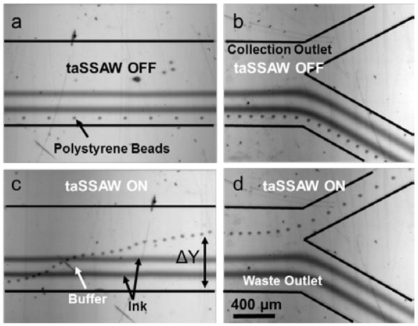
In order to demonstrate label-free vertical deflection of microparticles while maintaining the laminar characteristics of the incoming flow profile, we injected alternating layers of the buffer (DI water) and ink solutions through the five inlets of the microchannel where the 20.33 μm polystyrene bead solution was mixed in the first buffer stream (Fig. 2a and 2b). In the absence of the acoustic waves, polystyrene beads moved along the first stream of the flow closest to the lower sidewall, and left the microchannel through the waste outlet along with two streams of ink and one stream of separating buffer solution. We adjusted the flow rates for the optimum device operation, such that the fifth buffer stream partially went through the waste outlet, ensuring that only the coated cells and particles entered the collection outlet. We used 6, 1, 6, 1, and 20 μL/min flow rates for the particle solution, the first ink flow, the second buffer flow, the second ink flow, and the fourth buffer flow, respectively (Fig. 2a). Once we applied an RF signal to the tilted IDTs with input power of ~24 dBm and frequency of ~38 MHz, the polystyrene beads were pushed towards the pressure nodes. By using a 15° tilted IDT alignment, the microbeads were forced to migrate along the pressure nodes and crossed alternating streams of ink and buffer solutions with the aid of the flow field in the microchannel. Finally, the microbeads left the device from the collection outlet (Fig. 2c and 2d) in the buffer solution (Supplementary Video 1).
Fig. 2.
Demonstration of taSSAW-based particle deflection. 20.33 μm polystyrene partciles, the ink solutions, and the buffers are flowing in five layers when the taSSAW is OFF in the (a) active region, and (b) microchannel outlet region. (c) When the taSSAW is ON, the particles are pushed to the pressure nodes and migrate across the two ink solutions by the flow field, and (d) exit the device at the collection outlet.
The amount of the vertical deflection (ΔY) of the microparticles along the y-axis depends largely on the particle size, particle density, applied acoustic power, and the wavelength of the taSSAW according to equations 1 and 2. Compared with non-tilted SSAW and travelling SAW, taSSAW has the advantage of larger deflection and minimized acoustic streaming, respectively. In addition, the taSSAW utilizes multiple pressure nodal lines which are positioned across the channel and aligned with the tilt angle so that the particles that escape from one pressure nodal line can be trapped by the next nodal line and complete the migration across the channel. In this study, we chose the taSSAW devices with ~38 MHz frequency (wavelength: 50 μm). Since the volume of the particle is in the numerator of equation 1, and it is a cubic function of the particle radius, the particle diameter strongly affects the amount of the vertical deflection. We plotted the vertical deflections of 9.51, 15.45, and 20.33 μm diameter polystyrene microbeads with respect to the applied acoustic power (Fig. 3). For all the deflection experiments, we kept the total flow rate at 34 μL/min. The deflection distance was measured from the y-coordinate of the initial position that a particle enters the taSSAW field to the y-coordinate of the final position that the particle exists the taSSAW field. The maximum deflection for the 20.33 μm polystyrene beads occurred at the acoustic power of 26 dBm, at which the 9.51 μm particles were not significantly deflected (Fig. 3b).
Fig. 3.
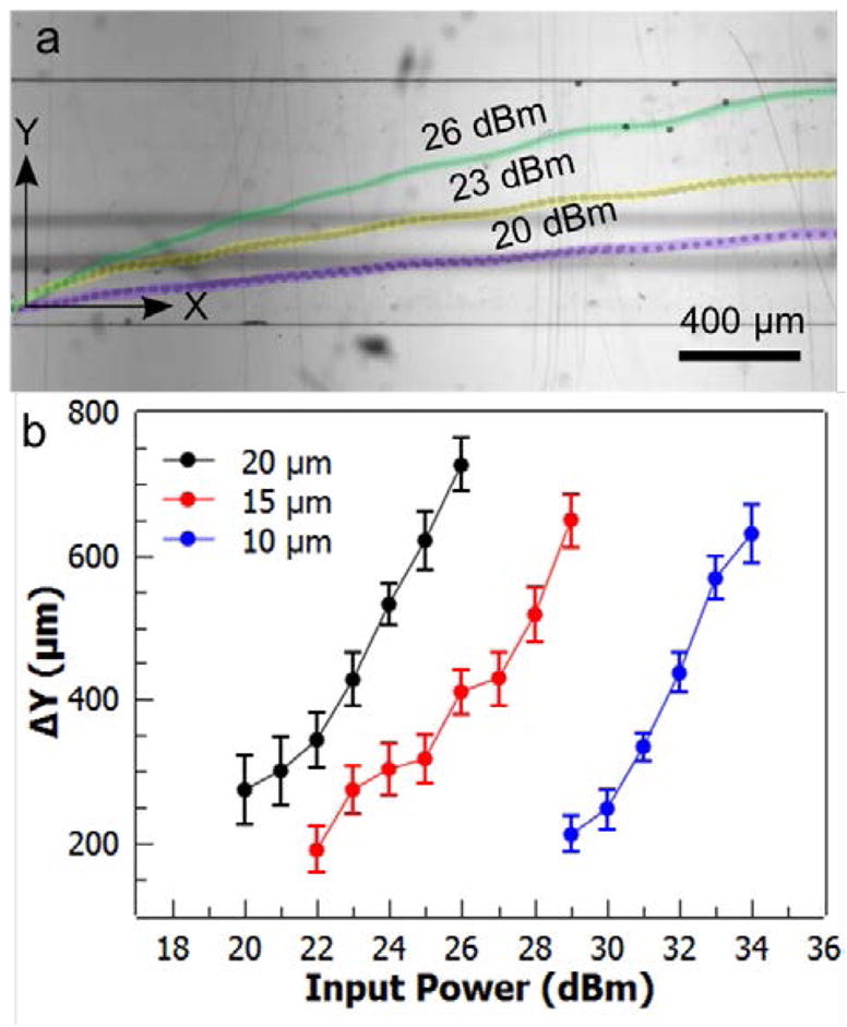
Characterization of particle deflection. (a) Stacked images of 20.33 μm particles crossing the microchannel at different acoustic powers. (b) Deflections of 9.51, 15.45, and 20.33 μm polystyrene particles are plotted at varying acoustic power values. Error bars represent standard deviation (n = 10).
In our current design, a minimum deflection of ~460 μm is required for the microparticles (with ~40 μm initial offset from the channel wall) to enter the collection outlet. For the sufficient deflection of the 9.51 μm particles, we varied the applied power from 29 dBm to 34 dBm and found that we could deflect the particles to the collection outlet with powers greater than ~32 dBm. With the current channel dimensions, total flow rate, and the SSAW frequency, the two streams of ink solutions started mixing beyond the acoustic power of 35 dBm (Supplementary Figure S1). The required deflection distance for particles to reach the collection outlet can be reduced by decreasing the thickness of the fluid layers, and/or by shifting the bifurcation point of the outlets closer to the bottom sidewall.
Single-layer coating of microparticles and HeLa cells
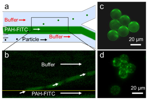
In order to demonstrate single-layer coating of the polystyrene particles and HeLa cells, we injected the particle/cell solution to inlet 1 (5 μL/min), the DI water buffer solution to inlet 2 (4 μL/min), PAH-FITC solution to inlets 3 and 4 (total 5 μL/min), and the final buffer solution to inlet 5 (20 μL/min) (Fig. 4a). Negatively charged carboxylate functionalized 20 μm polystyrene particles and inherently negatively charged HeLa cells were deflected by the taSSAWs and coated with the fluorescently labeled, positively charged PAH-FITC solution through electrostatic attraction (Fig. 4b). We subtracted the fluorescence image of the PAH-FITC stream when taSSAW was off from the fluorescence image when the taSSAW was on, to clearly show the coated particles leaving the PAH-FITC stream (Fig. 4b). The fluorescence imaging of the polystyrene microparticles and HeLa cells acquired from the collection outlet revealed the conformal coating of the particles and HeLa cells (Fig. 4c and 4d).
Fig. 4.
Single-layer coating of 20 μm negatively charged polsytyrene particles and HeLa cells. (a) The particles and the cells are vertically deflected through a fluorescenlty labeled positively charged PAH solution. (b) After removing the background fluorescene intensity of the PAH stream, coated polystyrene particles are seen leaving the stream. (c) The particles and (d) HeLa cells collected from the the collection outlet show conformal coating through fluorescene imaging.
Double-layer coating of microparticles
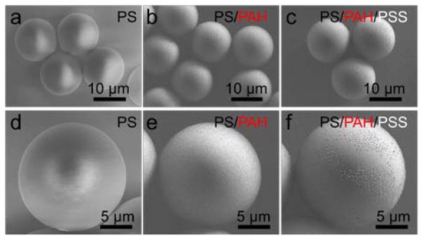
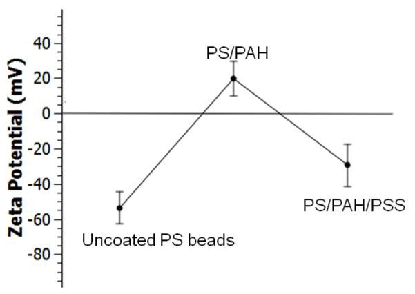
In order to demonstrate the capability of our platform for multiple-layer coating, we conducted a proof-of-concept experiment using PAH and PSS polyelectrolytes for double-layer polystyrene microparticle coating. Polyelectrolyte multilayers are highly applicable for biomolecule immobilization with preserved bioactivity.56 In addition, thin polyelectrolyte coatings enable tailored encapsulated carriers for specific cells or tissues.47 Poly(allylamine hydrochloride) (PAH) and poly(styrene sulfonate) (PSS) coated microparticles are widely used in drug encapsulation and improving the stability of encapsulated enzymes.48,49 For double-layer coating demonstration, negatively charged 20 μm diameter particles, positively charged PAH solution, the first buffer solution, negatively charged PSS solution, and the second buffer solution were injected at the flow rates of 4, 3, 4, 3, and 20 μL/min, respectively. At the current flow rates, the particles spend about 200–400 ms in each coating solution. By chaining the flow rates, the width of the coating streams can be increased which can in turn increase the time particles are dipped in the streams. We did not explore different flow rates in this particular work. For comparison purposes, we also coated the particles with only PAH solution by replacing PSS solution with the buffer solution. The SEM images of the uncoated polystyrene microparticles in Fig. 5a and 5d were used to compare the surface of the single-layer and double-layer coated particles. The uncoated microparticles showed smooth surfaces with no visible topography. On the other hand, the particles collected after crossing only the PAH solution show a rougher surface topology compared to the uncoated particles, suggesting PAH coating (Fig. 5b and 5e). The particles which crossed both PAH and PSS solutions showed further increase of the surface roughness, indicating the addition of the second layer. Zeta potential measurement of the uncoated, single-layer PAH- and double-layer PAH/PSS-coated 20 μm polystyrene microparticles indicated zeta potential values of −53.8 mV, 19.7 mV, and −29.4 mV, respectively (Fig. 6). Zeta potential indicates the electrostatic potential difference between the Stern layer on the surface of a particle and the bulk of the suspension liquid. Negative Zeta potential suggests that the particles have a negative surface charge as in the case of the carboxylate-functionalized polystyrene particles, and positive values suggest a net positive surface charge in the same suspension medium. The magnitude of the Zeta potential indicates the stability and agglomeration limit of a dispersion. The transition of the zeta potential from negative to positive and again to negative suggests the presence of alternating layers after electrostatic-based coating of the particles. It is also important to note that we did not observe significant differences of the surface morphology or the zeta potential of the coated beads by changing the acoustic input power at the current working frequency.
Fig. 5.
SEM analysis of (a) the uncoated, (b) PAH coated and (c) PAH/PSS coated polstyrene microparticles. (d) Uncoated polystyrene particles show smooth surfaces. (e) Single-layer (PAH) and (f) double-layer (PAF/PSS) coating shows increasing surface roughness compared to the uncoated particles.
Fig. 6.
Zeta potential of uncoated polystyrene (PA), single-layer PAH coated, and double-layer PAH/PSS coated particles. Error bars represent standard deviation of 6 measurements.
Conclusions
In summary, we introduced an acoustofluidic approach of on-chip particle and cell coating by implementing taSSAWs in a PDMS microchannel with multiple inlets. We demonstrated deflection and migration of microparticles across the microchannel while maintaining the laminar characteristics of the incoming flows. Negatively charged 20 μm polystyrene particles and HeLa cells were efficiently coated with a fluorescently labelled PAH solution. Furthermore, we demonstrated the ability of our system to realize multi-layer coating by passing 20 μm microparticles through PAH, PSS, and buffer solutions. With the advantages of being label-free, simple, versatile, and biocompatible, our taSSAW-based particle-coating method can be useful in many biomedical and biochemical applications.
Supplementary Material
Acknowledgments
We thank Dr. James Lata and Zhangming Mao for helpful discussions. We acknowledge support from the National Institutes of Health (R01 GM112048 and R33 EB019785) and the National Science Foundation (CBET-1438126 and IDBR-1455658). Bugra Ayan and Adem Ozcelik acknowledge support from Turkey’s Ministry of National Education.
Footnotes
Electronic Supplementary Information (ESI) available: Fig. S1 shows the power on the laminar flow of multiple flows. Video S1 shows the deflection and migration of the polystyrene microparticles through multiple flows while preserving the laminar flow profile.
References
- 1.Jaffrezic-Renault N, Martelet C, Chevolot Y, Cloarec JP. Sensors. 2007;7:589–614. [Google Scholar]
- 2.van Reenen A, de Jong AM, den Toonder JMJ, Prins MWJ. Lab Chip. 2014;14:1966. doi: 10.1039/c3lc51454d. [DOI] [PubMed] [Google Scholar]
- 3.Zhang H, Liu D, Shahbazi MA, Mäkilä E, Herranz-Blanco B, Salonen J, Hirvonen J, Santos HA. Adv Mater. 2014;26:4497–4503. doi: 10.1002/adma.201400953. [DOI] [PubMed] [Google Scholar]
- 4.Langer R. Acc Chem Res. 2000;33:94–101. doi: 10.1021/ar9800993. [DOI] [PubMed] [Google Scholar]
- 5.García-Alonso J, Fakhrullin RF, Paunov VN, Shen Z, Hardege JD, Pamme N, Haswell SJ, Greenway GM. Anal Bioanal Chem. 2011;400:1009–13. doi: 10.1007/s00216-010-4241-3. [DOI] [PubMed] [Google Scholar]
- 6.El-Ali J, Sorger PK, Jensen KF. Nature. 2006;442:403–11. doi: 10.1038/nature05063. [DOI] [PubMed] [Google Scholar]
- 7.Wang Z, Kim MC, Marquez M, Thorsen T. Lab Chip. 2007;7:740. doi: 10.1039/b618734j. [DOI] [PubMed] [Google Scholar]
- 8.Kim HS, Devarenne TP, Han A. Lab Chip. 2015;15:2467–2475. doi: 10.1039/c4lc01316f. [DOI] [PubMed] [Google Scholar]
- 9.Pamme N. Curr Opin Chem Biol. 2012;16:436–443. doi: 10.1016/j.cbpa.2012.05.181. [DOI] [PubMed] [Google Scholar]
- 10.Peyman SA, Iles A, Pamme N. Lab Chip. 2009;9:3110. doi: 10.1039/b904724g. [DOI] [PubMed] [Google Scholar]
- 11.Peyman SA, Iles A, Pamme N. Chem Commun. 2008:1220. doi: 10.1039/b716532c. [DOI] [PubMed] [Google Scholar]
- 12.Xie YL, Wang MJ, Yao SJ. Langmuir. 2009;25:8999–9005. doi: 10.1021/la9014338. [DOI] [PubMed] [Google Scholar]
- 13.Whitesides GM. Nature. 2006;442:368–73. doi: 10.1038/nature05058. [DOI] [PubMed] [Google Scholar]
- 14.Streets AM, Huang Y. Biomicrofluidics. 2013 doi: 10.1063/1.4789751. [DOI] [PMC free article] [PubMed] [Google Scholar]
- 15.Marina OC, Sanders CK, Kaduchak G, Goddard GR, Graves SW. Anal Methods. 2011;3:2573. [Google Scholar]
- 16.Tarn MD, Lopez-Martinez MJ, Pamme N. Anal Bioanal Chem. 2014;406:139–161. doi: 10.1007/s00216-013-7363-6. [DOI] [PubMed] [Google Scholar]
- 17.Karle M, Miwa J, Czilwik G, Auwärter V, Roth G, Zengerle R, von Stetten F. Lab Chip. 2010;10:3284. doi: 10.1039/c0lc00129e. [DOI] [PubMed] [Google Scholar]
- 18.Gossett DR, Tse HTK, Dudani JS, Goda K, Woods TA, Graves SW, Di Carlo D. Small. 2012;8:2757–2764. doi: 10.1002/smll.201200588. [DOI] [PubMed] [Google Scholar]
- 19.Tsai SSH, Wexler JS, Wan J, Stone HA. Appl Phys Lett. 2011;99:153509. [Google Scholar]
- 20.Tarn MD, Fakhrullin RF, Paunov VN, Pamme N. Mater Lett. 2013;95:182–185. [Google Scholar]
- 21.Tarn MD, Elders LT, Peyman SA, Pamme N. RSC Adv. 2015;5:103776–103781. [Google Scholar]
- 22.Kantak C, Beyer S, Yobas L, Bansal T, Trau D. Lab Chip. 2011;11:1030. doi: 10.1039/c0lc00381f. [DOI] [PubMed] [Google Scholar]
- 23.Song S, Choi S. J Micromechanics Microengineering. 2014;24:25007. [Google Scholar]
- 24.Yamada M, Kobayashi J, Yamato M, Seki M, Okano T. Lab Chip. 2008;8:772. doi: 10.1039/b718281c. [DOI] [PubMed] [Google Scholar]
- 25.Rambach RW, Skowronek V, Franke T. RSC Adv. 2014;4:60534–60542. [Google Scholar]
- 26.Franke T, Abate AR, Weitz DA, Wixforth A. Lab Chip. 2009;9:2625. doi: 10.1039/b906819h. [DOI] [PubMed] [Google Scholar]
- 27.Destgeer G, Lee KH, Jung JH, Alazzam A, Sung HJ. Lab Chip. 2013;13:4210. doi: 10.1039/c3lc50451d. [DOI] [PubMed] [Google Scholar]
- 28.Devendran C, Gunasekara NR, Collins DJ, Neild A. RSC Adv. 2016;6:5856–5864. [Google Scholar]
- 29.Skowronek V, Rambach RW, Schmid L, Haase K, Franke T. Anal Chem. 2013;85:9955–9959. doi: 10.1021/ac402607p. [DOI] [PubMed] [Google Scholar]
- 30.Augustsson P, Åberg LB, Swärd-Nilsson AMK, Laurell T. Microchim Acta. 2009;164:269–277. [Google Scholar]
- 31.Mao X, Lin SCS, Dong C, Huang TJ. Lab Chip. 2009 doi: 10.1039/b820138b. [DOI] [PubMed] [Google Scholar]
- 32.Ding X, Li P, Lin SCS, Stratton ZS, Nama N, Guo F, Slotcavage D, Mao X, Shi J, Costanzo F, Huang TJ. Lab Chip. 2013;13:3626–49. doi: 10.1039/c3lc50361e. [DOI] [PMC free article] [PubMed] [Google Scholar]
- 33.Li S, Guo F, Chen Y, Ding X, Li P, Wang L, Cameron CE, Huang TJ. Anal Chem. 2014;86:9853–9859. doi: 10.1021/ac502453z. [DOI] [PMC free article] [PubMed] [Google Scholar]
- 34.Guo F, Li P, French JB, Mao Z, Zhao H, Li S, Nama N, Fick JR, Benkovic SJ, Huang TJ. Proc Natl Acad Sci U S A. :2014. doi: 10.1073/pnas.1422068112. [DOI] [PMC free article] [PubMed] [Google Scholar]
- 35.Tang SY, Ayan B, Nama N, Bian Y, Lata JP, Guo X, Huang TJ. Small. 2016;12:3861–3869. doi: 10.1002/smll.201600737. [DOI] [PMC free article] [PubMed] [Google Scholar]
- 36.Ahmed D, Ozcelik A, Bojanala N, Nama N, Upadhyay A, Chen Y, Hanna-Rose W, Huang TJ. Nat Commun. 2016;7:11085. doi: 10.1038/ncomms11085. [DOI] [PMC free article] [PubMed] [Google Scholar]
- 37.Chen Y, Fang Z, Merritt B, Strack D, Xu J, Lee S. Lab Chip. 2016 doi: 10.1039/c5lc01420d. [DOI] [PubMed] [Google Scholar]
- 38.Hashmi A, Heiman G, Yu G, Lewis M, Kwon HJ, Xu J. Microfluid Nanofluidics. 2012;14:591–596. [Google Scholar]
- 39.Mulvana H, Cochran S, Hill M. Adv Drug Deliv Rev. 2013;65:1600–1610. doi: 10.1016/j.addr.2013.07.016. [DOI] [PubMed] [Google Scholar]
- 40.Lei J, Glynne-Jones P, Hill M. Phys Fluids. 2016;28:12004. [Google Scholar]
- 41.Li S, Ding X, Mao Z, Chen Y, Nama N, Guo F, Li P, Wang L, Cameron CE, Huang TJ. Lab Chip. 2015;15:331–338. doi: 10.1039/c4lc00903g. [DOI] [PMC free article] [PubMed] [Google Scholar]
- 42.Hawkes JJ, Barber RW, Emerson DR, Coakley WT. Lab Chip. 2004;4:446–52. doi: 10.1039/b408045a. [DOI] [PubMed] [Google Scholar]
- 43.Petersson F, Nilsson A, Jönsson H, Laurell T. Anal Chem. 2005;77:1216–1221. doi: 10.1021/ac048394q. [DOI] [PubMed] [Google Scholar]
- 44.Li P, Mao Z, Peng Z, Zhou L, Chen Y, Huang P, Truica CI. Proc Natl Acad Sci U S A. 2015;112:4970–4975. doi: 10.1073/pnas.1504484112. [DOI] [PMC free article] [PubMed] [Google Scholar]
- 45.Ding X, Peng Z, Lin SCS, Geri M, Li S, Li P, Chen Y, Dao M, Suresh S, Huang TJ. Proc Natl Acad Sci U S A. 2014;111:12992–12997. doi: 10.1073/pnas.1413325111. [DOI] [PMC free article] [PubMed] [Google Scholar]
- 46.Li S, Ren L, Huang PH, Yao X, Cuento RA, McCoy JP, Cameron CE, Levine SJ, Huang TJ. Anal Chem. 2016;88:5655–5661. doi: 10.1021/acs.analchem.5b03383. [DOI] [PMC free article] [PubMed] [Google Scholar]
- 47.Heuberger R, Sukhorukov G, Vörös J, Textor M, Möhwald H. Adv Funct Mater. 2005;15:357–366. [Google Scholar]
- 48.Srivastava R, Brown JQ, Zhu H, McShane MJ. Macromol Biosci. 2005;5:717–727. doi: 10.1002/mabi.200500061. [DOI] [PubMed] [Google Scholar]
- 49.Sato K, Seno M, Anzai JI. Polymers (Basel) 2014;6:2157–2165. [Google Scholar]
- 50.Ding X, Lin SCS, Kiraly B, Yue H, Li S, Chiang IKIK, Shi J, Benkovic SJ, Huang TJ. Proc Natl Acad Sci U S A. 2012;109:11105–11109. doi: 10.1073/pnas.1209288109. [DOI] [PMC free article] [PubMed] [Google Scholar]
- 51.Liu Z, Kim YJ, Wang H, Han A. J Acoust Soc Am. 2016;139:332–349. doi: 10.1121/1.4939737. [DOI] [PubMed] [Google Scholar]
- 52.Yosioka K, Kawasima Y. Acustica. 1955;5:167–173. [Google Scholar]
- 53.Doinikov AA. J Acoust Soc Am. 1997;101:713–721. [Google Scholar]
- 54.Doinikov AA. J Fluid Mech. 1994;267:1. [Google Scholar]
- 55.Bruus H. Lab Chip. 2012;12:1014. doi: 10.1039/c2lc21068a. [DOI] [PubMed] [Google Scholar]
- 56.Gribova V, Auzely-Velty R, Picart C. Chem Mater. 2012;24:854–869. doi: 10.1021/cm2032459. [DOI] [PMC free article] [PubMed] [Google Scholar]
Associated Data
This section collects any data citations, data availability statements, or supplementary materials included in this article.


