Abstract
3D printing an anatomically accurate, functional flow loop phantom of a patient’s cardiac vasculature was used to assist in the surgical planning of one of the first native transcatheter mitral valve replacement (TMVR) procedures. CTA scans were acquired from a patient about to undergo the first minimally-invasive native TMVR procedure at the Gates Vascular Institute in Buffalo, NY. A python scripting library, the Vascular Modeling Toolkit (VMTK), was used to segment the 3D geometry of the patient’s cardiac chambers and mitral valve with severe stenosis, calcific in nature. A stereolithographic (STL) mesh was generated and AutoDesk Meshmixer was used to transform the vascular surface into a functioning closed flow loop. A Stratasys Objet 500 Connex3 multi-material printer was used to fabricate the phantom with distinguishable material features of the vasculature and calcified valve. The interventional team performed a mock procedure on the phantom, embedding valve cages in the model and imaging the phantom with a Toshiba Infinix INFX-8000V 5-axis C-arm bi-Plane angiography system.
Results
After performing the mock-procedure on the cardiac phantom, the cardiologists optimized their transapical surgical approach. The mitral valve stenosis and calcification were clearly visible. The phantom was used to inform the sizing of the valve to be implanted.
Conclusion
With advances in image processing and 3D printing technology, it is possible to create realistic patient-specific phantoms which can act as a guide for the interventional team. Using 3D printed phantoms as a valve sizing method shows potential as a more informative technique than typical CTA reconstruction alone.
Keywords: 3D Printing, Image Segmentation, CT Segmentation, Surgical Planning, Native Valve, Mitral, TMVR
1. INTRODUCTION
Transcatheter Aortic Valve Replacement (TAVR) is an alternative method to treat aortic valve disease for patients who are unable to undergo traditional Surgical Aortic Valve Replacement (SAVR) 1, 2. This endovascular procedure employs a catheter-based delivery system to implant a balloon-expandable bioprosthetic valve within a diseased aortic valve. In typical cases, access is established through the femoral artery; the catheter is guided through the aortic arch into the aortic root. Although the method has existed since 2002, it was not until the successful results of the PARTNER A and B trials were released in 2011 that the procedure gained widespread attention and implementation in structural heart programs around the country1, 3–5.
With recent advancements in TAVR technology and techniques, interventional cardiologists have begun to experiment with alternative access routes and indications for use. A particularly exciting cross-application of this technology is for mitral valve replacement. This appears as a reasonably safe and effective treatment for patients who have had mitral valve replacement surgery in the past; a result facilitated by the surgically implanted bioprosthetic valve rings serving as ideal structures to anchor TAVR valves in the mitral position3, 6.
Recently, a few case-briefings have been published which report successful procedures which implant TAVR devices into patients with native mitral valve (MV) stenoses of calcific etiology7–9. The complex anatomy of the mitral apparatus and heterogeneous etiology of native mitral valve disease pose particular challenges to catheter-based interventions3, 6, 9–11. Of particular concern is ensuring that the implanted valve will be sufficiently supported by the mitral annulus and leaflets. At the moment, no method or test exists which can a priori confirm the mechanical soundness of a valve implanted at the mitral position of a particular patient. As such, physicians must rely on their best medical judgment & experience to predict if the degree and distribution of mitral calcification will provide a sufficient support structure for the implanted valve3, 12.
In addition, no general sizing method has been proposed for TAVR valves implanted in the (native) mitral position. Commonly used TAVR devices, such as the Edwards SAPIEN Series (Edwards Life-Sciences, Irvine CA) and the Medtronic CoreValve Series (Medtronic, Dublin Ireland), are designed to fit in the circular cross section of the aortic valve. In order to prevent perivalvular leak, the “D-shaped” mitral annulus, and “saddlehorse” leaflets, must be sufficiently sealed around these circular valves. Therefore, a fine balance exists between a valve sufficiently sized to prevent perivalvular regurgitation and an oversized device which needlessly risks left ventricular outflow tract obstruction and hemodynamic imbalance13, 14.
A possible solution to these challenges lays in patient-specific 3D printed phantoms; this technology has emerged as a valuable method for clinicians to gain direct insight into the anatomical features and geometries which underpin the ambiguities and associated challenges of novel procedures15–19. Providing physicians with patient-specific, usable phantoms provides an opportunity to conduct multiple non-surgical mock procedures; allowing for evidence-based decisions to be made about their most complex and unusual cases, potentially shifting the entire paradigm of treatment plan optimization15, 20.
Herein details the first-in-print report of a 3D printed cardiac vascular phantom aiding in the procedural planning of one of the first transcatheter native MV replacements conducted in the United States. The development of functional cardiac vascular phantoms for preparation of structural heart interventions can be thought of as a novel innovation which has the potential to greatly impact personalized patient care. In order to accelerate adoption and advancement of these techniques, it is crucial to understand workflow processes allowing accurate and functional models to be efficiently created.
2. MATERIALS AND METHODS
2.1 Patient Profile
The patient is a 59-kg, 65-year-old African American woman who was initially referred to the Gates Vascular Institute Structural Heart Clinic to evaluate her worsening heart symptoms. She presented with a past medical history notable for severe mitral stenosis (or calcific etiology), moderate-to-severe aortic stenosis, atrial fibrillation, end-stage renal disease (on hemodialysis), hepatitis C, and breast cancer (currently in remission; treated with chemoradiation). The patient was evaluated by two cardiothoracic surgeons and deemed unsuitable for SAVR, with a predicted operative mortality risk in excess of 25%, based on the Society for Thoracic Surgeons database (STS Score). Left untreated, the patient’s rapidly progressing heart failure would have proven fatal on a timescale of months, potentially weeks. The patient was offered a choice between palliative care or an off-label transcatheter native mitral valve replacement procedure. After consultation with her family, the patient elected to undergo the transcatheter procedure. Collection and analyses of these scans were covered under IRB approval.
2.2 Image Acquisition
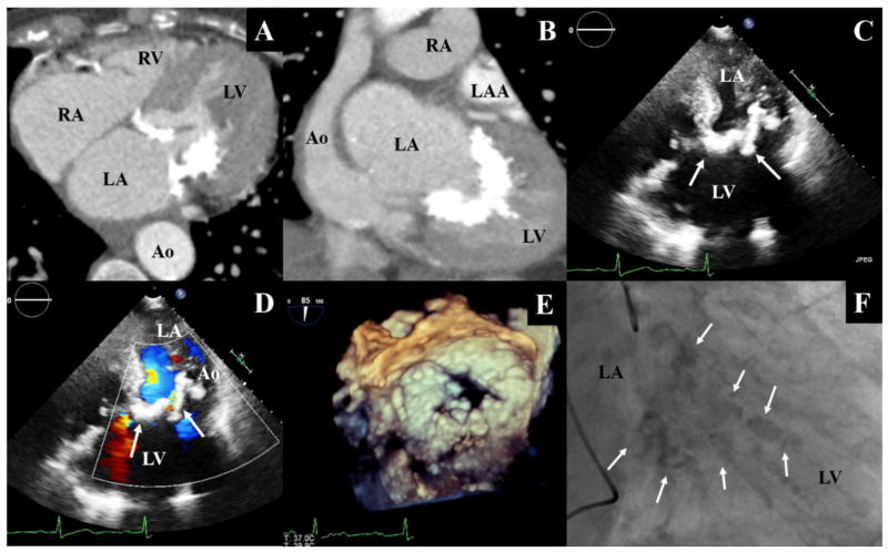
The following imaging studies were ordered by the interventional team prior to the procedure (see Figure 1): Transthoracic Echocardiogram (TTE), Transesophageal Echocardiogram (TEE), Left and Right Heart Cardiac Catheterization, and Variable Pitch Electrocardiograph (ECG) gated CT Angiography with IV Contrast (CTA). While these scans were originally used to provide the physicians with diagnostic and anatomic information, they also provided the necessary volumetric data required to create the patient-specific phantom 15, 16.
Figure 1.
Heart chambers and calcified mitral apparatus observed during a CTA study in axial (A) and frontal (B) planes. The calcified mitral annulus and leaflets observed during a transthorasic echocardiography(C), with doppler (D). A view of the calcified mitral apparatus generated by 3-Dimensionall Transesophageal Echocardiography (E). The calcified mitral apparatus as observed under fluoroscopy during a cardiac catheterization procedure (F). Arrows indicate location of the calcified valve; LV: Left Ventricle; LA: Left Atrium; LAA: Left Atrial Appendage; Ao: Aorta; RV: Right Ventricle; RA: Right Atrium
All available imaging data was reviewed using the 3D reconstruction and visualization utilities provided by the Toshiba Vitrea 3D Enterprise Suite (Vital Images Inc., Minnetonka, MN). The rapid 3D rendering capabilities of this software allowed us to quickly evaluate the quality of each image set in the series, qualitatively. The highest quality image set depicting the cardiac structures and thoracic aorta during systole (70% cardiac cycle) was identified, and the corresponding DICOM files were isolated and exported for further processing.
2.3 Phantom Manufacturing
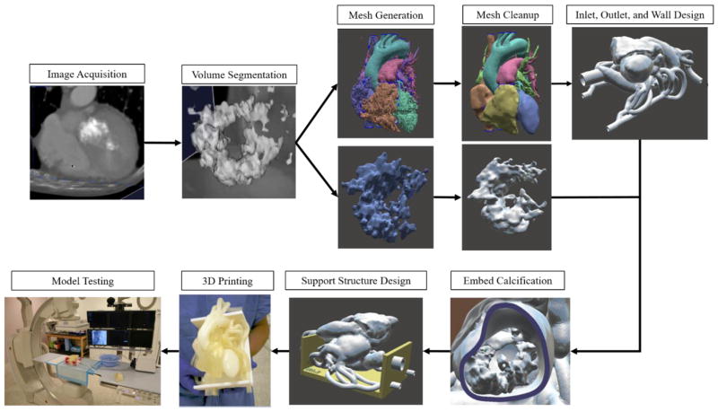
The methods used to create this cardiac phantom have been adapted from those proposed by Ionita et al. 16, 18. Figure 2 outlines the nine core steps involved in the workflow process to manufacture and use the cardiac phantom.
Figure 2.
Workflow components used to construct the 3D printed model.
2.3.1 Stero-Lithographic File Creation
We opted to adapt the functionality of the Vascular Modeling Toolkit (VMTK) to perform the volume segmentation of the cardiac structures 21. The process of generating usable surface renders with VMTK proceeds as follows. First the CTA image data from the set of DICOM files was written into an intermediate visualization toolkit (VTK) XML binary image date container (VTI file). An interactive volume of interest (VOI) method was called to define and write a new VTI file containing only the cardiothoracic structures of interest 22. Though not technically required, VOI isolation reduces user-time-cost and computational expense associated with processing unnecessary data.
To ensure that the mitral calcification was unmistakably identifiable in later steps, the anatomy was segmented in two parts which could later be combined in an assembly. The first volume corresponds to the patient’s cardiac vasculature; this anatomy includes the four heart chambers, thoracic aorta, superior and inferior vena cava, and pulmonary arteries. The second volume corresponds to only the highly radio-attenuating cardiothoracic structures; in this context, the anatomy corresponds to the MV calcification and spine – geometries which do not overlap and whose shapes can be fully preserved during isolation in post processing.
To perform the volume segmentation, an interactive level-set segmentation procedure was called in VMTK 21, 22. This interactive tool proceeds via two main steps. First, user-specified methods are used to identify desired features within the images. Once all desired features have been initialized, a corresponding initial level set file is generated and seamlessly piped to a level set deformation method. The user inputs desired deformation parameters, and the final level-set file is written to the file directory.
For this particular case, image features were identified by applying a combination of colliding fronts, threshold, and isosurface initialization methods. Geodesic level set and gradient feature image types were specified for the deformation model, along with the number of iterations, propagation scaling, curvature scaling, advection scaling, and branch merging parameters22. Since the optimal values for these parameters vary on a case-by-case basis, experimentation was needed in order to determine the most effective values. Unfortunately, level set segmentation is known to be a fairly computationally intensive process; this project’s complex feature geometry and large number of iterations (700) required to produce a suitable render resulted in prohibitively long processing times (timescale of multiple hours) on normal desktop machines. In order to perform the computations in a reasonable amount of time, it was necessary to employ the high performance computing capabilities of the University at Buffalo Center for Computational Research (CCR). The job was run on one of the CCR remote visualization nodes, allocating 12 Xeon cores, 256GB memory, and 2 Nvidia Tesla M2075 GPUs to the process (completing in roughly 20 minutes).
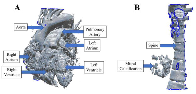
VMTK was then used to call a standard marching cubes algorithm, converting the level sets into corresponding stereolithographic (STL) meshes; a file format which is amenable to post-processing and 3D printing. The final STL files written for each of the two parts are shown in Figure 3.
Figure 3.
The two STL files corresponding to anatomy of the cardiac vasculature (A) and MV calcification/spine (B), as segmented by VMTK from the patient’s CTA scan.
2.3.2 Mesh Cleanup and Functional Design
Autodesk Meshmixer, a free STL editor, was used to cleanup and repair the meshes. Although time consuming, the cleanup is essential to eliminate artifacts of the segmentation process which are problematic for 3D printing. We are mainly concerned with removing spikes, filling holes, and smoothing outcroppings. In order to avoid changing the macro geometry of the mesh, only small sections of any part were revised at a given time. After each part was appropriately repaired, the cardiac body was stitched back together to form three solid, continuous bodies: the cardiac vasculature, the MV calcification, and the spine (which was later deleted after serving as a spatial orientation reference).
Since the procedure only involves access to the left heart anatomy, a functional flow loop was only created within the lumen of the left atrium, left ventricle, and thoracic aorta. At the request of the interventional team, the right ventricle and pulmonary arteries were included in the model to serve as landmarks; these were printed as solids in the final model.
The left atrium, thoracic aorta, and left ventricle were separated from the right heart anatomy. In an attempt to mimic hemodynamic flow behavior, flow loop inlets were positioned at the locations where the superior and inferior pulmonary veins intersect with the left atrium. Outlets to the flow loop were positioned in two places: the first at a distal section of the descending thoracic aorta, the second from the great vessels. To finish the flow loop, the surface mesh of the left heart structures required an internal cavity which fluid would flow through. This was accomplished by extruding these structures 3mm outwards along surface normals. This preserved the internal shape of the heart chambers and constructed a body with adequate support.
As we intended to use a multi-material printer to fabricate the calcific region and cardiovascular region from different materials, we kept the calcific region and heart geometry as separate parts in the assembly. Though not formally united, the Meshmixer “attract” tool was used to sit each part flush against the other.
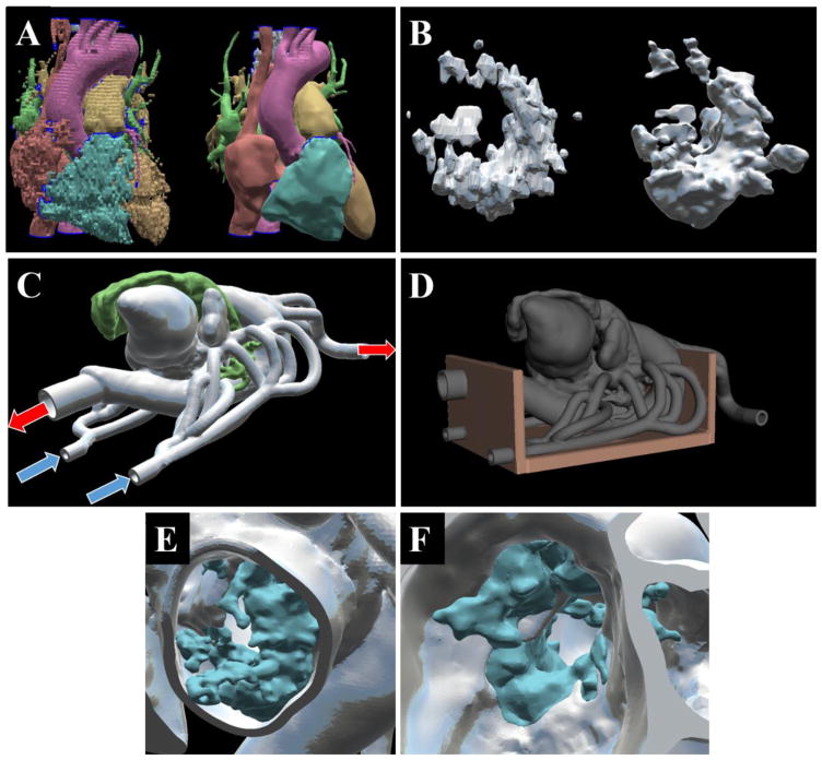
The final step before sending the phantom to the 3D printer was to create a support structure for the model. One of the requirements for construction of the phantom was that when the base is placed flat on a table, the model orients the heart (tilt, angle, rotation) as if the patient is lying supine. This was achieved by using Meshmixer to build a box like base along the plane which the spine sat on. This base was connected to the most posterior portions of the model and additional supporting structures were manually drawn in to ensure that the walls of the flow loop would be able to support the weight of the system. Figure 4 displays illustrates the components and results of the mesh cleanup and functional design process.
Figure 4.
The cardiovascular structures originally acquired from segmentation (left) compared to the structure after mesh cleanup (right) with AutoDesk Meshmixer (A). The mitral calcification originally acquired (left) compared to its final cleaned version (right) (B). Inlets and outlet designs for the cardiac flow loop – blue arrows indicate inlets into the left atrium, red arrows indicate outlets from the great vessels and descending aorta (C). The design of the phantom support structure (D). A view of the calcification (blue) incorporated into the mitral annulus (grey) as shown from a left ventricle view (E), and left atrial view (F).
2.4 3D Printing
Fabrication of the final assembly, consisting of the vascular volume, mitral calcification, and support structure, was contracted out to Objet-Stratasys Inc. (Eden Praire, MN). Two models were printed on the Objet 500 Connex3 PolyJet 3D Printer system. This multi-material printer is capable of maximum dimensions of 490 × 390 × 200 mm, prints ultra-fine 16 μm layers, with an accuracy of 20 – 85 μm for features below 50 mm and up to 200 μm for full model size. The model was printed with the materials stated in Table 1. Material properties were chosen to mimic vascular tissue (for the anatomy), and bone (for the calcified region). The support structure was printed with stiff and durable material in order to provide adequate support to the model.
Table 1.
The material properties of the digital blend used to print each component of the cardiac model.
| Part | Material | Tensile Strength (MPa) | Elongation at Break (%) | Durometer (Shore A Scale) | Tensile Tear Resistance (Kg/cm) |
|---|---|---|---|---|---|
| Vascular Anatomy | Tango+ | 0.8–1.5 | 170–220 | 26–28 | 2–4 |
| Support Structure | FLX-MT-S85DM | 5.0–7.0 | 55–65 | 80–85 | 23–25 |
| Calcification | DM_9770 | 3.5–5.0 | 65–80 | 68–72 | 15.5–17.5 |
| Support Material in Model 1 | SUP705 | n/a | n/a | n/a | n/a |
| Support Material in Model 2 | SUP706 (soluble) | n/a | n/a | n/a | n/a |
2.5 Phantom Testing and Evaluation
The transcatheter mitral valve replacement procedure was performed at the Gates Vascular Institute (Buffalo, NY) in a hybrid operating room – a surgical theatre dually equipped to function as an angiography lab. On the morning of the procedure, after the case-briefing, the interventional team convened at one of the dedicated research angiography suites in the Toshiba Stroke and Vascular Research Center. The most important components of the TAVR delivery systems were donated by Edwards life-sciences for this procedure: the transapical sheath, delivery catheters, valve crimper, and metal cages of the 23mm SAPIEN XT and 20mm SAPIEN 3 valves, the two valves which the interventional team was interested in evaluating before performing the procedure. The phantoms were connected to a cardiac pump circulating a glycerol-water solution, and multiple mock procedures were performed.
In an attempt to mimic the radio-attenuating properties of the patient’s calcified valve, the mock-calcification on one of the cardiac phantoms was painted with a thin coating of a tantalum powder and superglue. The other phantom was left untouched for comparison. In addition to the two full phantoms, a cross section of the calcified MV was available for visual inspection by the physicians.
In addition to photographs, the mock-procedure was documented by recording the live fluoroscopy feed for later analysis and comparison to the feed acquired during the real procedure. The Toshiba Infinix INFX-8000V C-arms were also used to acquire baseline and post-implantation 3D rotational digital angiography (3D-DA) scans of the phantom. The Toshiba Vitrea Enterprise software suite automatically processed the 3D-DA data and generated CT-like slices which were suitable for volume reconstruction. VMTK was used, in a similar manner as described in section 2.3.1, to generate STL renders of the pre and post valve-implanted phantoms. A combined thresholding and fast-marching initialization method was used in order to minimize the effects of x-ray scattering by the cobalt chromium frame of the SAPIEN valve cages. CloudCompare, a free 3D point-cloud editing and analysis software package, was then used in order to align, finely-register, and perform quantitative comparisons between each of the segmented volumes (see section 3.4)23.
3. RESULTS
3.1 Phantom Fabrication Results
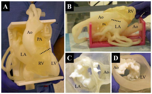
A patient-specific, anatomically accurate cardiac phantom of left heart vasculature and severe mitral valve stenosis is shown in figure 5. The model was successfully designed and fabricated with three weeks’ notice from the interventional team; its purpose was to serve as a procedural planning tool for one of the first transcatheter native mitral valve replacement procedures performed in the United States.
Figure 5.
Top-down view of the cardiac phantom; the dotted-line indicates the approximate location of the mitral annular plane if projected straight down into the model (A). A view of the right side of the second (identical) phantom; the dotted line indicates approximate planar location and diameter of the mitral annulus if projected straight into the model (B). A sectional view of the mitral annulus and calcification as seen from the left atrium (C). A sectional view of the mitral annulus and calcification as seen from the left ventricle (D). LV: Left Ventricle; LA: Left Atrium; RV: Right Ventricle; Ao: Aorta; PA: Pulmonary Artery
Two multi-material phantoms were fabricated, along with a cross section of the mitral calcification. With the support of Stratasys Inc. (Eden Prairie, MN), one copy of the phantom was printed on a production model Objet 500 Connex3 3D printer (Figure 5B). The other copy was printed on an experimental version of the Objet 500 Connex3 which was able to fabricate the model with soluble support, SUP706 (Figure 5A). Aside from soluble support and a change in color, the models were identical in all aspects. The use of dissolvable 3D printing support material on this complex vascular model proved to be fairly successful; this model required only about 1/3rd the time (60 minutes) to adequately clean as compared to the model created with conventional support material.
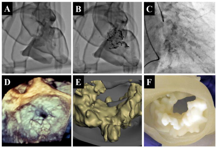
Figure 6 A,B,C compares fluoroscopy images of the two models to those recorded during the patient’s cardiac catheterization procedure. Unlike the patient’s fluoroscopy images, the walls of the phantoms are clearly resolved and project an outline of vasculature on the screen. In figure 6A, the unaltered phantom, the calcification’s intensity closely resembles what is observed in vivo. The annular plane, however, is difficult to place due to shadowing from the right ventricle. In contrast, the tantalum powder and superglue coated phantom, observed in figure 6B, provides an exceptional image of the calcification. Though it is unrealistic in clarity and resolution, with increasing contrast of the calcification by an average of 59% compared to the non-coated phantom, it allowed the physicians to understand the exact morphology and spatial orientation of calcification. While neither model is a perfect replica of physiological conditions, the dual approach allowed the team to get a better understanding of what they should expect to see during the procedure.
Figure 6.
Fluoroscopy images acquired with the C-Arm in the RAO 22 CRA 20 position for the non-altered phantom (A), the tantalum-powder coated phantom (B) and during the patient’s cardiac catheterization (C). Mitral apparatus calcification as viewed from three dimensional transesophageal echocardiogram (D), computer render segmentated from CTA scans (E), and a cross section of the 3D printed model (F).
A visual confirmation of the model’s calcific accuracy is provided in Figure 6 D,E,F. At the start of the procedure, 3D TEE images were acquired of the calcified mitral leaflets and annulus. The ventricular TEE view clearly distinguishes calcific buildup on mitral apparatus, matching features segmented from the CTA scans and subsequently printed.
3.2 Phantom Testing
A number of mock-interventions were performed by the intervention team on the morning of the procedure. The primary experimental location was in one of the research angiography suites in the Toshiba Stroke and Vascular Research Center; all images were generated on a Toshiba Infinix INFX-8000V 5-axis C-arm bi-Plane angiography imaging system. The phantom was placed on the angiography table and connected to a pulsatile pump (Harvard Apparatus, Holliston, MA); a glycerol-water mixture was circulated through the phantom to mimic blood flow with appropriate viscosity.
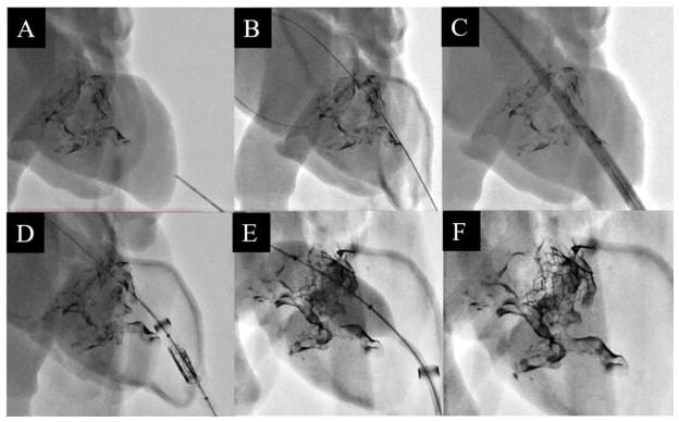
An expired (but functional) set of delivery devices, catheters, and metal cages of the 20mm SAPIEN 3 and 23mm SAPIEN XT were acquired from Edwards Life-Sciences (Irvine, CA). The mock-procedures were performed in as similar a manner to the real procedure as reasonable. The procedure was practiced in the mitral cutout section, with each of the valve cages later being implanted into the full phantoms. A series of fluoroscopy images depicting the six main steps (explained in figure 7 caption) in the transcatheter MV replacement procedure are shown in Figure 7; captured while implanting the 23mm SAPIEN XT valve in one of the phantoms.
Figure 7.
The apex of the left ventricle being punctured with a needle (A). A stiff guidewire fed across the mitral orifice and anchored in the left atrium (B). The dilator-sheath combo being fed over the guidewire to allow access into the left atrium (C). With the dilator removed, the crimped valve is fed into the ventricle within the sheath lumen (D). The 23 mm balloon-expandable SAPIEN XT valve being placed implanted into the mitral orifice (E). The guidewire and sheath are retracted and the ventricle apex is sown closed, leaving the implanted valve behind (F).
3.3 Clinical Results
After the mock-intervention, the surgical team successfully performed the procedure on the patient. Figure 8 shows the most pertinent images taken from the intra-procedure fluoroscopy and TEE feed. An inverted 23mm Edwards SAPIEN XT valve (Edwards Life-Sciences, Irvine CA) was placed in the mitral position under rapid pacing. After deployment, Doppler TEE showed significant perivalvular leak, a likely result of the valve being located too atrial. In order to stabilize ventricular/atrial pressures, it was determined that a second 23mm SAPIEN XT valve would be implanted within the annular/ventricular portion of the first. After deployment, perivalvular leak and atrial/ventricular pressure imbalances stabilized, but high aortic valve velocities and gradients indicated LVOT obstruction. An alcohol septal ablation was performed in order to attempt to correct this. The patient has survived past the 30-day mark.
Figure 8.
Fluoroscopy shots taken during placement of the first (A) and second valve (B).
3.4 Clinical Analysis of Experimental Results
To perform a more detailed post-operative analysis, 3D rotational digital angiography (3D-DA) scans were acquired of each phantom both pre-procedure and post valve-implant. The 3D-DA data was processed into CT-like slices and VMTK was used to digitally reconstruct each phantom’s left heart geometry and, for post-procedure scans, implanted valve. Measurements of the phantom’s LVOT diameter both pre and post valve-implant were taken. In addition, the anatomical consequences of implanting TAVR-type devices into the phantom’s mitral position were quantitatively described with CloudCompare, a point-cloud analysis software package 23, 24.
The most significant result emerging from this analysis is the similarity in left ventricular outflow tract obstruction observed in the phantom to that of the patient. CT and TEE studies conducted prior to the patient’s procedure indicated a LVOT diameter of 2.5cm. Post implant, intra-operative TEE confirmed that ventricular/aortic hemodynamic imbalance was the result of LVOT obstruction, with a measured LVOT diameter of 1.53cm. The LVOT diameters of the reconstructed baseline, 23mm SAPIEN XT, and 20mm SAPIEN 3 implanted phantoms were then measured. The average LVOT diameter for the baseline (pre-op) phantom was about 2.6 cm. This changed to an average LVOT diameter of ~2.0cm for the 20mm SAPIEN 3 model, and between 1.0–1.5cm for the 23mm SAPIEN XT model. However, it should be noted that the 3D-DA scan resolution for the SAPIEN XT phantom was of particularly poor quality in the region surrounding the mitral calcification and LVOT. Accurate measurements of LVOT diameter were nearly impossible to acquire along the midline of the LVOT/intraventricular septum wall. Highly pronounced x-ray scattering was present at every surface coated with tantalum powder.
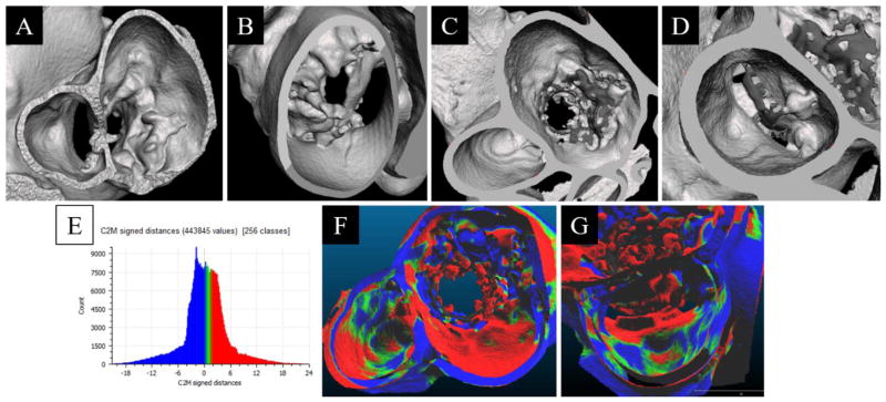
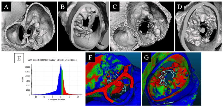
The geometric consequences of aortic valve replacement in the native mitral position observed in the SAPIEN XT and SAPIEN 3 phantoms have been evaluated. The post-op, reconstructed phantom STL was converted to a point-cloud and registered to the baseline phantom mesh. It is important to note that the implanted valve was segmented out separately from the phantom walls; after the distance calculation was performed the valve geometry could be rendered in without skewing the results. The cloud to mesh (C2M) signed distance function was calculated and the results are shown in figures 10 and 11. The explicit description of these results are presented as histograms in figures 9 and 10 24.
Figure 10.
Segmented view of the baseline phantom geometry, reconstructed from 3D-DA, as if viewing from the left Atrium/LVOT (A) and left ventricle (B). Segmented view of the 23mm SAPIEN XT implant phantom, reconstructed from 3D-DA, as if viewing from the left atrium (C) and LVOT (D). Histogram of the signed distance transform between the baseline and implanted geometries (E). Comparison of the difference between the Baseline and 23mm SAPIEN XT implant phantom overlain on the implant phantom with a viewpoint centered from the left atrium (F) and the LVOT (G). Color scale represents direction of vertex motion (green/blue mix is no change; blue is surface contraction; green and red is surface bulge).
Figure 9.
Segmented view of the baseline phantom geometry, reconstructed from 3D-DA, as if viewing from the left Atrium/LVOT (A) and left ventricle (B). Segmented view of the 20mm SAPIEN 3 implant phantom, reconstructed from 3D-DA, as if viewing from the left Atrium/LVOT (C) and left ventricle (D). Histogram of the signed distance transform differences between the baseline and implanted geometries (E). Comparison of the difference between the Baseline and 20mm SAPIEN 3 implant phantom overlain on the implant phantom with a viewpoint centered from the LVOT (F) and the ventricle apex (G). Color scale represents direction of vertex motion (green/blue mix is no change; blue is surface contraction; green and red is surface bulge).
4. DISCUSSION
This study details the first reported use of 3D printed patient-specific cardiovascular phantoms to aid in the planning of a new transcatheter native MV replacement procedure. We have described the methods which have been used to quickly create, test, and analyze multi-material 3D printed models in a clinical setting. This example demonstrates the usefulness and feasibility of creating case-specific phantoms for structural heart interventions; providing physicians with unparalleled visualization of complex anatomy along with the ability to practice novel and complex procedures on a specific patient’s anatomy before performing the case.
4.1 Clinical Impact
Prior to the procedure, mitral annulus measurements were acquired from CTA and TEE scans; these indicated that the annulus would accept either a 20mm Edwards SAPIEN 3 or a 23mm Edwards SAPIEN XT valve (Edwards Life-Sciences, Irvine CA). Though functionally similar, the geometry of the cobalt-chromium cages of the SAPIEN XT and SAPIEN 3 cages are macroscopically and mechanically different. The main concern was whether the valve cages would apply sufficient radial force to deform the posterior mitral calcification, “opening” the mitral ring, or whether the posterior calcification would hold and force the valve anteriorly against the Intraventricular Septum (IVS), resulting in Left Ventricular Outflow Tract (LVOT) obstruction. Though it would initially appear attractive to use the smaller valve which might mitigate the risks of LVOT obstruction by applying less force to the IVS, the 20mm SAPIEN 3 is the smallest valve available and has 33% less cross sectional area for blood to travel across compared to the 23mm SAPIEN XT. If the smaller valve was used, that the patient may not have been able to achieve full ventricular filling during diastole; potentially failing to correct the high velocities and valve pressure gradients which originally lead to hemodynamic imbalance.
Therefore, the utility of this model was to provide the physicians with a better understanding of the factors which influence this apparent tradeoff between effectiveness and safety. During the mock-deployments conducted in the cross section mitral model (Figure 7 E), the interventional team evaluated the valve positioning and balloon behavior with regard to influence on the calcific burden and posted deployment shape, height, and cross sectional area of the valve. The visualization capabilities helped to inform their decision to use a 23mm SAPIEN XT valve (14.3mm height) during the procedure. This decision was made in order to minimize LVOT interference while simultaneously gaining maximal annulus coverage from the valve’s high radial strength25.
In order to build accurate and useful models, the investigators need to have a clear understanding of the pathophysiology, anatomic importance, and imaging characteristics of cardiovascular anatomy and disease states. A multidisciplinary team of physicians, nurses, researchers, technicians, and engineers were needed to make the project a success. The exact design of our model was driven by the end-user, the physicians’ intended needs and requirements; it was crucial to keep the interventional team involved during development so they could convey their thoughts and ideas. As an example, some of the key incites shared during this project were that only the location and material properties of both the mitral calcification and left heart anatomy needed be replicated accurately. It was not required for the mitral or aortic valves (left heart structures) to function in any fashion at all – since only a cage would be implanted in the model.
4.2 Phantom Design and Fabrication
VMTK was used to segment the cardiac geometry from the patient’s CTA scans21. The framework primarily employs the level sets method – a topology-flexible approach to image segmentation. The method describes the evolution of an embedded zero-level isosurface, Ø(x, t), under image and shape-based forces by a partial differential equation of form21, 22, 26:
The three terms on the right hand side of this equation describe the position dependent propagation speed of surface inflation, G(x), the mean zero-level surface curvature smoothness constraint, , and the mean vector field regulated surface advection, ∇P(x) 22. The influence of each term is regulated by user-defined weighting parameters: w1, w2, and w3.
Rather than performing a centerline-based level set initialization, which can introduce an operator-dependent influence on resulting geometry, colliding fronts and threshold based initialization methods were used to generate an initial surface located within the capture radius of the advection term21, 22. This allowed us to negate the influence of G(x) by setting w1 = 0. Another standardizing measure was permitted due to the relatively large difference in intensity values between the cardiac vasculature and tissue. This allowed the surface advection parameter to reasonably be set at w3 = 1. The effect is to imply that surface evolution is driven, proportionally, by the image intensity gradient magnitude – effectively forcing advection towards the vascular lumen22, 27.
In order to regulate the effect of noise around the mitral apparatus, a non-zero weight was assigned to the curvature scaling parameter w2. The inclusion of w2 weighting acts to penalize the evolution of highly curved features in the segmentation. Though not formally regarded as a smoothing step, this method was used to normalize the influence of noise in problematic regions. Though effective, identifying a suitable parameter value for w2 proved to be a time-consuming process; the effects could only be evaluated after the full deformation model was iteratively computed. The optimization of w2 was further complicated due to its sensitivity; while small values yield negligible influence, the topological shrinking effect of mean curvature flow quickly become overbearing as the weighting is increased21, 22, 26, 27. After much experimentation, the value w2 = 0.13 was used.
The application of multi-material printing to the development of this structural heart phantom was particularly exciting. Selectively segmenting out the calcified tissue from the rest of the cardiovascular anatomy allowed us to preserve the location and orientation of the calcification. However, because the phantom also needed to be completed in just a few weeks from its initial proposal, we were not able to validate the biomimetic accuracy of the phantom material properties compared to those in vivo. In this case, we simply had to use the literature and investigator intuition to make our best guess at what we should specify the tissue and calcium “hardness” to be. Even with various unknowns in the model’s properties and biomimetic potential, the analysis conducted on the phantom’s LVOT compression (Figure 9E and 10E) seems to suggest that it may have some amount of predicative power when considering the anatomic consequences of structural heart intervention.
The development of patient-specific 3D printed models show promise in both clinical and product development applications. Advances are rapidly occurring in the cornerstone techniques underlying methods used to create useful patient-specific phantoms – image segmentation, direct STL export from PACS systems, 3D editing software, and multi-material 3D printing – contributing to increased attention to these methods as an avenue for innovation. Benefits are already being realized by the patients of the forward thinking physicians who are driving the use and development of this technology. In addition, the constant technical communication with the researchers and engineers appears to push the intervention team to think about their plan and the procedure from a new perspective. Patient-specific 3D printing is a powerful tool for visualization and pre-procedure treatment planning. This technology may significantly improve patient care by providing a more informative method to test new devices, visualize complex anatomy, and realistically perform procedures on a patient’s anatomy before actually performing the procedure.
5. CONCLUSION
With advances in image processing and 3D printing technology, it is possible to create accurate patient-specific phantoms which will further inform the development of novel procedures. The phantom in this study was designed, functionalized, and printed with just three weeks’ notice from the intervention team. The primary goals were to provide visualization of the calcific burden and allow for valve deployment within the mitral orifice. In order to achieve this, it was necessary to employ advances in image segmentation, mesh manipulation, functional design strategies, and multi-material 3D printing. While there are a variety of challenges which need to be overcome regarding assigning material properties and radio-attenuation, the phantom was able to achieve both of its primary goals. After practicing on the 3D printed model designed in this study, the interventional team successfully performed the procedure on the patient.
Acknowledgments
We would like to thank Paul Dressel of SUNY Buffalo Neurosurgery, Keith Mages of Kaleida Health Libraries, as well as Liza Pope and Megan Russ of the Toshiba Stroke and Vascular Research Center at SUNY Buffalo for providing technical assistance during completion of this project. Partial support for this project has been provided by: NIH Grant R01EB00287; The SUNY at Buffalo Center for Computational Research; Toshiba Medical Systems Corp (Otawara, Tochigi Prefecture, Japan); Edwards Life-Sciences (Irvine, CA); and Stratasys Inc (Eden Prairie, MN).
References
- 1.Svensson LG, Tuzcu M, Kapadia S, et al. A comprehensive review of the PARTNER trial. The Journal of Thoracic and Cardiovascular Surgery. 2013;145(3, Supplement):S11–S16. doi: 10.1016/j.jtcvs.2012.11.051. [DOI] [PubMed] [Google Scholar]
- 2.Leon MB, Smith CR, Mack M, et al. Transcatheter Aortic-Valve Implantation for Aortic Stenosis in Patients Who Cannot Undergo Surgery. New England Journal of Medicine. 2010;363(17):1597–1607. doi: 10.1056/NEJMoa1008232. [DOI] [PubMed] [Google Scholar]
- 3.Wilbring M, Alexiou K, Tugtekin SM, et al. Pushing the limits - Further evolutions of transcatheter valve procedures in the mitral position, including valve-in-valve, valve-in-ring, and valve-in-native-ring. Journal of Thoracic and Cardiovascular Surgery. 2014;147(1):210–219. doi: 10.1016/j.jtcvs.2013.09.021. [DOI] [PubMed] [Google Scholar]
- 4.Panchal HB, Ladia V, Desai S, et al. A Meta-Analysis of Mortality and Major Adverse Cardiovascular and Cerebrovascular Events Following Transcatheter Aortic Valve Implantation Versus Surgical Aortic Valve Replacement for Severe Aortic Stenosis. The American Journal of Cardiology. 2013;112(6):850–860. doi: 10.1016/j.amjcard.2013.05.015. [DOI] [PubMed] [Google Scholar]
- 5.Miller DC, Blackstone EH, Mack MJ, et al. Transcatheter (TAVR) versus surgical (AVR) aortic valve replacement: Occurrence, hazard, risk factors, and consequences of neurologic events in the PARTNER trial. The Journal of Thoracic and Cardiovascular Surgery. 2012;143(4):832–843.e13. doi: 10.1016/j.jtcvs.2012.01.055. [DOI] [PubMed] [Google Scholar]
- 6.De Backer O, Piazza N, Banai S, et al. Percutaneous Transcatheter Mitral Valve Replacement: An Overview of Devices in Preclinical and Early Clinical Evaluation. Circulation: Cardiovascular Interventions. 2014;7(3):400–409. doi: 10.1161/CIRCINTERVENTIONS.114.001607. [DOI] [PubMed] [Google Scholar]
- 7.Akujuo AC, Dellis SL, Britton LW, et al. Transcatheter aortic and mitral valve implantation (TAMVI) in native rheumatic valves. Journal of Cardiac Surgery. 2015;30(11):813–816. doi: 10.1111/jocs.12612. [DOI] [PubMed] [Google Scholar]
- 8.Elkharbotly A, Delago A, El-Hajjar M. Simultaneous transapical transcatheter aortic valve replacement and transcatheter mitral valve replacement for native valvular stenosis. Catheterization and Cardiovascular Interventions. 2015 doi: 10.1002/ccd.26078. [DOI] [PubMed] [Google Scholar]
- 9.Witkowski A, Kuśmierski K, Chmielak Z, et al. First-In-Man Simultaneous Transcatheter Aortic and Mitral Valve Replacement to Treat Severe Native Aortic and Mitral Valve Stenoses. JACC: Cardiovascular Interventions. 2015;8(10):1399–1401. doi: 10.1016/j.jcin.2015.03.039. [DOI] [PubMed] [Google Scholar]
- 10.Guerrero M, Greenbaum A, O’Neill W. First in human percutaneous implantation of a balloon expandable transcatheter heart valve in a severely stenosed native mitral valve. Catheterization and Cardiovascular Interventions. 2014;83(7):E287–E291. doi: 10.1002/ccd.25441. [DOI] [PubMed] [Google Scholar]
- 11.Hasan R, Mahadevan VS, Schneider H, et al. First in human transapical implantation of an inverted transcatheter aortic valve prosthesis to treat native mitral valve stenosis. Circulation. 2013;128(6):e74–e76. doi: 10.1161/CIRCULATIONAHA.113.001466. [DOI] [PubMed] [Google Scholar]
- 12.Cheung A, Webb JG, Barbanti M, et al. 5-Year Experience With Transcatheter Transapical Mitral Valve-in-Valve Implantation for Bioprosthetic Valve Dysfunction. Journal of the American College of Cardiology. 2013;61(17):1759–1766. doi: 10.1016/j.jacc.2013.01.058. [DOI] [PubMed] [Google Scholar]
- 13.Vaquerizo B, Theriault-Lauzier P, Piazza N. Percutaneous Transcatheter Mitral Valve Replacement: Patient-specific Three-dimensional Computer-based Heart Model and Prototyping. Rev Esp Cardiol (Engl Ed) 2015 doi: 10.1016/j.rec.2015.08.005. [DOI] [PubMed] [Google Scholar]
- 14.Aboulhosn J, Child JS. Left Ventricular Outflow Obstruction: Subaortic Stenosis, Bicuspid Aortic Valve, Supravalvar Aortic Stenosis, and Coarctation of the Aorta. Circulation. 2006;114(22):2412–2422. doi: 10.1161/CIRCULATIONAHA.105.592089. [DOI] [PubMed] [Google Scholar]
- 15.Russ M, O’Hara R, Setlur Nagesh SV, et al. Treatment planning for image-guided neuro-vascular interventions using patient-specific 3D printed phantoms. 9417 doi: 10.1117/12.2081997. 941726-941726-11. [DOI] [PMC free article] [PubMed] [Google Scholar]
- 16.Ionita CN, Mokin M, Varble N, et al. Challenges and limitations of patient-specific vascular phantom fabrication using 3D Polyjet printing. Proc SPIE Int Soc Opt Eng. 2014;9038:90380M. doi: 10.1117/12.2042266. [DOI] [PMC free article] [PubMed] [Google Scholar]
- 17.Ionita CN, Garcia VL, Bednarek DR, et al. Effect of injection technique on temporal parametric imaging derived from digital subtraction angiography in patient specific phantoms. Proc SPIE Int Soc Opt Eng. 2014;9038:90380l. doi: 10.1117/12.2041347. [DOI] [PMC free article] [PubMed] [Google Scholar]
- 18.Kurenov SN, Ionita C, Sammons D, et al. Three-dimensional printing to facilitate anatomic study, device development, simulation, and planning in thoracic surgery. The Journal of Thoracic and Cardiovascular Surgery. 2015;149(4):973–979.e1. doi: 10.1016/j.jtcvs.2014.12.059. [DOI] [PubMed] [Google Scholar]
- 19.Mokin M, Setlur Nagesh SV, Ionita CN, et al. Comparison of Modern Stroke Thrombectomy Approaches Using an In Vitro Cerebrovascular Occlusion Model. American Journal of Neuroradiology. 2015;36(3):547–551. doi: 10.3174/ajnr.A4149. [DOI] [PMC free article] [PubMed] [Google Scholar]
- 20.Maragiannis D, Jackson MS, Igo SR, et al. Replicating Patient-Specific Severe Aortic Valve Stenosis With Functional 3D Modeling. Circ Cardiovasc Imaging. 2015;8(10) doi: 10.1161/CIRCIMAGING.115.003626. [DOI] [PubMed] [Google Scholar]
- 21.Antiga L, Manini S. The Vascular Modeling Toolkit. 2015. [Google Scholar]
- 22.Antiga L, Piccinelli M, Botti L, et al. An image-based modeling framework for patient-specific computational hemodynamics. Med Biol Eng Comput. 2008;46(11):1097–112. doi: 10.1007/s11517-008-0420-1. [DOI] [PubMed] [Google Scholar]
- 23.Girardeau-Montaut D. CloudCompare Version 2.6.1. EDF R&D, Telecom ParisTech; 2015. [Google Scholar]
- 24.Lague D, Brodu N, Leroux J. Accurate 3D comparison of complex topography with terrestrial laser scanner: Application to the Rangitikei canyon (N-Z) ISPRS Journal of Photogrammetry and Remote Sensing. 2013;82:10–26. [Google Scholar]
- 25.Rahimtoola SH. Choice of Prosthetic Heart Valve in AdultsAn Update. Journal of the American College of Cardiology. 2010;55(22):2413–2426. doi: 10.1016/j.jacc.2009.10.085. [DOI] [PubMed] [Google Scholar]
- 26.Whitaker RT. A level-set approach to 3D reconstruction from range data. International journal of computer vision. 1998;29(3):203–231. [Google Scholar]
- 27.Sethian JA. Theory, algorithms, and applications of level set methods for propagating interfaces. Acta Numerica. 1996;5:309–395. [Google Scholar]


