

Abstract
Vitrification, a kinetic process of liquid solidification into glass, poses many potential benefits for tissue cryopreservation including indefinite storage, banking, and facilitation of tissue matching for transplantation. To date, however, successful rewarming of tissues vitrified in VS55, a cryoprotectant solution, can only be achieved by convective warming of small volumes on the order of one mL. Successful rewarming requires both uniform and fast rates in order to reduce thermal mechanical stress and cracks, and to prevent rewarming phase crystallization. Here we present a scalable nanowarming technology for 1 to 80 mL samples using radiofrequency-excited mesoporous silica coated iron oxide nanoparticles in VS55. Advanced imaging including Sweep Imaging with Fourier Transform and micro computed tomography were used to verify loading and unloading of VS55 and nanoparticles and successful vitrification of human dermal fibroblast cells, porcine arteries, and porcine aortic heart valve leaflet tissue. Nanowarming was then used to demonstrate uniform and rapid rewarming at > 130 °C/min in both physical (1 to 80 mL) and biological systems (1 to 50 mL). Nanowarming yielded viability that matched control and/or exceeded gold standard convective warming in 1 to 50 mL systems, and improved viability compared to slow warmed (crystallized) samples. Finally, biomechanical testing displayed no significant biomechanical property changes in blood vessel length or elastic modulus after nanowarming compared to untreated fresh control porcine arteries. In aggregate, these results demonstrate new physical and biological evidence that nanowarming can improve the outcome of vitrified cryogenic storage of tissues in larger sample volumes.
Introduction
A major limitation of transplantation is the ischemic injury that tissue and organs sustain during the time between recovery from the donor and implantation in the recipient. Maximum tolerable organ preservation for transplantation by hypothermic storage is typically 4 h for heart and lungs; 8 to 12 h for liver, intestine, and pancreas; and up to 36 h for kidney transplants (8). In many cases, such limits actually prevent viable tissue or organs from reaching recipients. For instance, over 60% of donor hearts and lungs are not used or transplanted due in part to exceeding their maximum hypothermic preservation times (8). Further, if only half of these discarded organs were transplanted, it has been estimated that wait lists for these organs could be extinguished within 2 – 3 years (8).
Cryopreservation and storage of biomaterials at low temperatures provides a potential revolution for tissue and organ recovery, allocation, and transplantation. At the very least, it would facilitate matching of donor and recipient tissues, increased geographic sharing, and better recipient preparation (8). Ultimately, long-term tissue preservation would increase utilization, improve short and long term graft function, and increase overall patient survival at potentially lower cost. Indeed, many smaller systems such as cells can now be successfully preserved by cryopreservation (9, 10) or vitrification, an approach which converts liquid to glass (11–13). However, in the case of larger systems such as tissues, cryopreservation in 1 to 4 M cryoprotective solutions often fails due to damage caused by ice crystal growth (14–16), thereby adversely affecting transplantation (15, 17). Nevertheless, with higher concentration solutions (6 to 8 M) viable tissues and organs such as rabbit kidneys have been diffusion or perfusion loaded, respectively, cooled and stabilized in the vitreous “glassy” or “amorphous” state without ice crystal growth at vapor phase nitrogen temperatures (−160 °C) (15, 17).
Unfortunately, advances in tissue and organ cooling for cryopreservation have not been matched by similar advances in rewarming. Two technological barriers have proven difficult to overcome. First, the critical warming rates (CWR) to avoid devitrification, the process of crystallization during warming, are typically an order of magnitude higher than the corresponding critical cooling rates (CCR) (3). CWR and CCR of common cryoprotectant vitrification solutions are listed in table S1. Second, these rates need to be sufficiently uniform throughout the material to avoid large thermal gradients, which produce thermal stress that often drives fractures or cracks within the tissue if they exceed the strength of the material (tensile strength of vitrified VS55 is 3.2 MPa) (18). While CWR and uniformity can be achieved by traditional convective warming in smaller 1 to 3 mL systems (15), no approach currently works for larger systems up to 80 mL in volume.
Our study builds on previous low volume physical (3) and theoretical work (4) to demonstrate that nanoparticle heating can improve tissue viability and prevent physical failure during warming after cryopreservation of larger volumes compared to the gold standard, convection. The ability of metallic nanoparticles to transduce radiofrequency (RF) and light energy for cancer therapy is already well established (5, 6). For instance, iron oxide materials that heat by superparamagnetic or ferromagnetic mechanisms in RF fields have been championed (7) and have led to clinical trials for glioma and other tumors in Europe (6). Here we describe a new scalable technology termed “nanowarming” that uses iron oxide nanoparticle heating physics for more uniform and rapid heating of larger volume cryopreserved porcine arterial and heart valve tissues as a notable contribution to regenerative medicine.
Results
Comparison of gold standard convection and nanowarming
Convective rewarming of cryopreserved biomaterials is still the gold standard for small volumes (< 3 mL) (15). However, as the volume increases, convective warming cannot prevent physical failure due to crystallization and/or cracking during warming. Nanowarming is a scalable technique that can rewarm cell and tissue systems from 1 to 80 mL as shown in Fig. 1. Biomaterials can be loaded with cryoprotectants (CPA) using existing methods for successful vitrification. The left panel in Fig. 1 depicts how thermal gradients and/or insufficient warming rates during convective warming can lead to failure in large volumes. In contrast, biological tissues are relatively transparent to alternating RF fields at hundreds of kHz, but generate significant heating when the nanoparticles are coupled with the magnetic field (right panel in Fig. 1). Then the homogeneity in heating of cryopreserved biological tissues depends only on the distribution of nanoparticles.
Fig. 1. Schematic illustrating tissue vitrification, convective warming, and nanowarming.
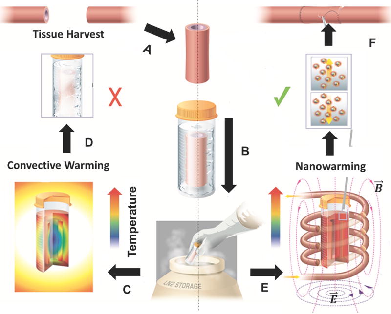
(A) Tissues are harvested from a donor. Representative harvest of a blood vessel is shown. (B) Tissues are loaded in a vial with cryoprotectant (VS55) and msIONPs in a stepwise protocol, vitrified by standard convection, and stored at cryogenic temperatures. Warming by standard convection (C), leads to failure in larger 50 mL systems (D). Nanowarming in an alternating magnetic field, an inductive RF coil that stimulates nanoparticle heating (E), avoids warming failure and renders the tissue suitable for further testing or use (F).
Nanoparticle coating and colloidal stability
Previously, we utilized RF excited magnetic nanoparticles within 1 mL cylindrical vials to demonstrate the possibility of nanowarming in non-biological systems with standard cryoprotectants (3). Nanowarming is dependent on heat generation from iron oxide nanoparticles (IONPs) that can be excited in a RF field. Fig. S1A explains the physics behind nanowarming, which relies on Brownian and Néelian relaxation for IONP heating. Nanoparticles are synthesized by coating a commercially available magnetic IONP with a mesoporous silica shell, followed by co-modification of polyethylene glycol (PEG) and trimethoxysilane (TMS) as previously described and shown in Fig. 2A (19).
Fig. 2. Iron oxide nanoparticle characterization.
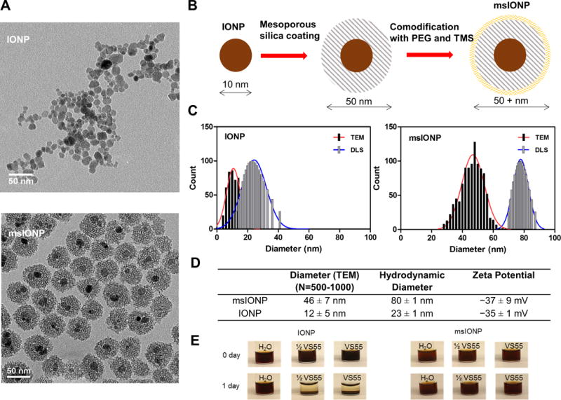
(A) Representative TEM images of IONPs and msIONPs. (B) Schematic detailing the synthesis of msIONPs. The IONPs were coated with mesoporous silica shell followed by co-modification of PEG and TMS on the surface of msIONPs. (C) Size distribution of IONPs and msIONPs quantified by dynamic light scattering (DLS) and by analyzing 500 − 1000 NPs from TEM images. (D) Table of parameters of IONPs and msIONPs. (E) Photographs depicting stability of msIONPs and IONPs in VS55 at room temperature over time.
Representative transmission electron microscopy (TEM) images demonstrate that uncoated IONPs are polydispersed and irregularly shaped with an average diameter of 12 nm, while mesoporous silica coated iron oxide nanoparticles (msIONPs) are relatively monodispersed with 1 to 2 iron oxide cores per particle and an average diameter of 50 nm (Fig. 2A). Fig. 2B illustrates the process of msIONPs production from the bare particles IONPs. Size distributions of IONPs and msIONPs are shown in Fig. 2C, while the detailed properties of IONPs and msIONPs are shown in Fig. 2D. In higher concentration ½ VS55 and full VS55 solutions, the PEG/TMS coated msIONPs remain in solution, while uncoated IONPs fall out of solution after several hours (Fig. 2E).
We used an inductive heating coil capable of creating internal heat generation of up to several MW/m3 in the vitrified material to analyze nanowarming in different sized systems. Throughout the text we indicate the specific absorption rate (SAR) measured by W/g Fe or W/m3 in the nanowarmed material, as a measure of internal heat generation where 1 × SAR is equal to 160 W/g Fe generated by 10 mg Fe/mL msIONPs in VS55 operating at 20 kA/m and 360 kHz RF. Immediate heating of IONPs still in suspension can be as high as 250 W/g Fe, however, once aggregated as shown in Fig. 2E this can drop the SAR to only 125 W/g Fe (20, 21). One way to avoid aggregation is by improving colloidal stability, indicated by a large absolute zeta potential for msIONP (> |15| mV) (22). Remaining in solution allows a consistent SAR of 160 W/g Fe for msIONP which was used for all further experiments (19).
Nanowarming scale up
The scale up of the radiofrequency inductive heating coil and system from a 1 kW to a 15 kW system is shown in fig. S1B–D. Specifically, the 1 mL, 1 cm diameter 2.5 turn coil for the 1 kW system was upgraded to an 80 mL, 5 cm, 4 turn coil for the 15 kW system. While the frequency range is similar (100 – 400 kHz), the maximum commercially specified field strength is almost 3 fold higher (80 vs. 25 kA/m), allowing a four-fold increase in SAR from the 1 kW to the 15 kW system. In general, samples ≤ 1 mL were rewarmed in 1 kW system (cells, heart valve leaflets and carotid artery rings) and ones ≥ 1 mL (artery segments) were rewarmed in 15 kW system to benefit from higher volume capacity of the coil and maximum induced magnetic field intensity.
Characterization of cryoprotectant VS55 loading and vitrification
To ensure vitrification, cells and tissues must be loaded with a cryoprotectant (CPA) solution such as VS55 before being cooled sufficiently rapidly and uniformly to the glassy state to avoid crystallization or cracking. Finding the minimum time for complete loading is important in order to avoid unnecessary toxicity from the CPA. Thus, we studied VS55 permeation kinetics experimentally with micro computed tomography (μCT) by modifying previous methods (23). We first imaged dilutions of VS55 by μCT to establish a calibration of VS55 concentration to Hounsfield Units (HU) (Fig. 3A inset), yielding 62 HU/M VS55. Then we imaged VS55 permeation by diffusion into porcine carotid arteries at 4 °C. We noted that tissue has a baseline of 80 HU (green dashed line, Fig. 3A) whereas the baseline for saline is 0 HU. We used 24 h to represent a fully-loaded sample (red dashed line, Fig. 3A). As the loading requires several hours to complete, we characterized the loading kinetics at 18 min intervals via μCT. During the first 18 min, the HU jumped from 80 to 430 HU on the loaded edge of the tissue (center to edge of yellow curve in Fig. 3A). In contrast, at this same time (center of yellow curve) the VS55 had barely reached the center of the artery (100 vs. baseline of 80 ± 10 HU). Identifying the centerline of the artery as 0.0 mm, or 0.4 mm from either edge, we then calculated diffusivity to be roughly 1.9 × 10⁻¹⁰ (m2/s) at 20 °C. This value is consistent with previous CPA diffusivity measurements when accounting for temperature (23).
Fig. 3. VS55 loading, vitrification, and nanowarming of porcine arteries.
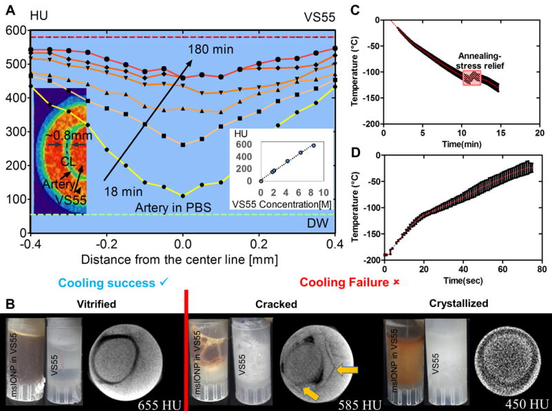
(A) Quantitation and distribution of VS55 loading over time in the wall of one out of three representative porcine arteries imaged in (B). The corresponding pseudocolor image shows green artery wall and red VS55 solution by μCT. The red dashed line represents the fully loaded HU. The green dashed line represents artery in PBS HU (n=3 for calibration curve). (B) Photographs and computed tomography images of three separate arteries in 1 mL vials demonstrating successful artery vitrification (left), failure due to cracking (middle), and failure due to crystallization (right). The density differences due to the cracking are noted by arrows in B. (C) Graph of temperature over time for convective cooling vitrification of arteries in 1 mL vials at 15 °C/min > CCR of VS55. (D) Graph of temperature over time for nanowarming at 20 kA/m and 360 kHz of the same arteries in (C) loaded with msIONP in VS55 in 1 mL vials. Nanowarming reached 130 °C/min which is > CWR of VS55.
After stepwise VS55 loading, we also used μCT to measure the success or failure of system vitrification. Ice crystallization yields a solid phase that is lower in density and HU than liquid or vitrified VS55. This will occur if the critical cooling rate of VS55 (2.5 °C/min) is not achieved (table S2). For instance, successful artery vitrification (Fig. 3B, bottom left) was achieved by cooling at 15 °C/min with an annealing step as shown in Fig. 3C, resulting in 655 HU after 24 h of VS55 loading. In contrast, cooling failures due to cracking or crystallization reduce HU to 585 and 450, respectively. Failure due to direct immersion into liquid nitrogen, yielding thermal gradients and ensuing stress that exceeds the yield stress of the system (table S2), is shown in Fig. 3B (middle). Cracks are distinguishable in the image as discontinuities in the artery wall (yellow arrow, Fig. 3B). In addition, Fig. 3B (right) shows crystallization failure that is indicative of the crystalline vs. amorphous phase. Fig. 3D shows the nanowarming rate of 130 °C/min, which far exceeds the CWR (table S2), applied to the successfully vitrified artery.
Limitations of gold standard convection and nanowarming
Preliminary calculations revealed the limitations of convection warming and the ideal volume of interest (VOI) for our nanowarming method. A simple one-dimensional (1D) conduction and thermal stress computational model with VS55 thermal properties in an infinite cylinder with variable radius was used to illustrate the limits of traditional convective warming (Fig. 4 and table S2). Assuming the convective coefficient (h) varies between 10 and 1000 W/m2K and solving the spatially distributed cooling and warming within these cylinders, a CCR of ≥ 2.5 °C/min was found to be achievable in a vial with radius ≤ 2.5 cm for h ≥ 10 W/m2K during cooling. However, the rates of warming achievable by convection are below the CWR of 50 °C/min for vials with a radius ≥ 0.5 cm. Thermal stress calculated on the basis of thermal gradients during nanowarming showed that the stress remained below the critical yield stress of the material for all radii. Convective rewarming, on the other hand, failed for vials > 1 mL (radius ≥ 0.5 cm) as shown in the modeling results in table S2. These findings have been verified by our measurements of success by nanowarming vs. convective failure at 50 mL and 80 mL.
Fig. 4. Nanowarming scale up from 1 kW to 15 kW inductive heating system.
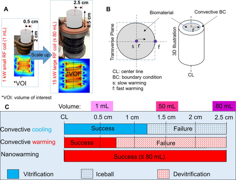
(A) Schematic of RF heating system scale up from 1 kW to 15 kW to enable heating up to 80 mL with an increased SAR. (B) The cross-sectional and 3D representations of the cylindrical system to be vitrified and convectively warmed or nanowarmed. (C) The limitations of gold standard convective cooling and rewarming vs. nanowarming on vitrification (success and failure) of 0.5 – 2.5 cm radius cylinders as reported numerically in table S2. Successful cooling (blue shading) and warming (red shading) are defined by the critical minimum cooling and warming rates for VS55 and thermal stress lower than 3.2 MPa. More details of this model are given in the Supplementary Materials.
Nanowarming of cells and tissues
Before moving into larger tissue systems, a proof of principle nanowarming study on human dermal fibroblasts (HDF) was performed. Here, the Hoechst-PI assay was used to assess successful CPA and msIONP loading, and various cooling and warming regimens (fig. S2). First, biocompatibility of VS55 alone and with msIONP during loading was demonstrated; thereafter, the benefits of nanowarming over slow convection warming with respect to cell viability were demonstrated. Fig. S2B shows that all viabilities remain high vs. control, confirming minimal toxicity after VS55 loading. Further, the viability of HDFs exposed to VS55 and msIONP (10 mg Fe/mL) was comparable to the cells that were only exposed to VS55 (P = 0.5264) and slightly lower than the ones that were kept in the culture medium (P = 0.04191) (fig. S2C). Fig. S2E shows that cells after nanowarming are more viable than control cells in media alone (P = 0.0039), which was a higher viability than cells in VS55 on ice for the same exposure time (P < 0.001) and higher than slow warming on ice (P < 0.0001). Furthermore, RF exposure alone had no significant effect on viability of the cells.
Next we measured the viability of nanowarmed and gold standard fast convective warmed porcine carotid arteries at 1 and 50 mL. Importantly, no significant viability changes were noted after VS55 loading steps with or without msIONPs (Fig. 5A top). After vitrification and heating the viabilities obtained via nanowarming, fast convective rewarming (~ 90 °C/min), and slow warming (~ 7 °C/min) are shown in Fig. 5A (bottom) using the resazurin (alamarBlue) assay as previously reported (15, 24). In the 1 mL system, the viability of nanowarmed sample showed no statistical difference from the fresh control sample (P = 0.0835) and was comparable to fast convective warming (P = 0.8767). The slow warmed sample showed a ~ 68% decline of viability compared to fresh control, presumably due to devitrification (P < 0.0001). Further, intermediate convective rewarming on ice (~ 40 °C/min) also proved to be ~ 16% less effective than nanowarming (P = 0.0482) (fig. S3). The viability data from these plots and others are listed and statistically compared in table S3 and table S4.
Fig. 5. Nanowarming maintains viability of porcine carotid in 1 to 50 mL systems.
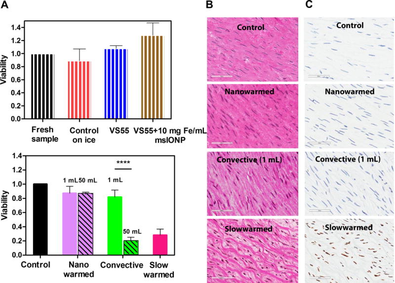
(A) Viability of porcine carotid artery normalized to the control (fresh tissue in growth media) as measured by alamarBlue assay and TUNEL stain. The upper plot shows the cytotoxicity effect of adding VS55 and 10 mg Fe/mL msIONP to the artery (n = 4 − 7). The striped bars represent viability of fresh samples normalized to control (black control = 100%), samples that were maintained on ice for the same period of time (1 − 2 h) (red, 89 ± 2%), samples that were exposed to VS55 (blue, 100 ± 1.4%) or VS55 and 10 mg Fe/mL msIONP (brown, 128 ± 19%). The bottom plot shows the artery viabilities after nanowarming (solid purple, 1 mL: 87 ± 10%, patterned purple, 50 mL: 86 ± 3%), fast convective heating (solid green, 1 mL: 82 ± 10%, patterned green, 50 mL: 20 ± 6%) and slow warming (pink, 1 mL: 28 ± 9%). In 1 mL, the nanowarmed sample viability is comparable to the fresh control and slow warmed sample showed a decline of viability compared to fresh control (P < 0.0001). In 50 mL, the nanowarmed sample viability is slightly lower than the fresh control (P = 0.0275) but comparable to nanowarmed sample in 1 mL (P = 0.9996). The fast convective warmed sample viability is significantly reduced in 50 mL (P < 0.0001). The statistical analyses of multiple comparisons of other possible conditions are included in table S4. N = 3 − 6 for both 1 mL and 50 mL systems; n = 4 − 7 in 1 mL system; n= 3 − 5 in 50 mL. N = number of pigs; n = number of arteries (B) Histological images of H&E stained control, nanowarmed, convective (1 mL), and slow warmed arteries. Scale bar is 60 μm. Normalized tissue white space compared to control: 2 ± 0.3%, P = 0.09 for nanowarmed samples, 31 ± 1%, P < 0.0001 for slow warmed convective samples. See also fig. S3. (C) TUNEL stained images corresponding to the same histology samples in B. All data is presented as the mean ± standard deviation.
The viability data is further supported by hematoxylin and eosin (H&E) and terminal deoxynucleotidyl transferase dUTP nick end labeling (TUNEL) stained histology (Figs. 5B & C). The nanowarmed artery smooth muscle cells in the media showed well-defined normal nuclear morphology and structure. In contrast, the slowly warmed devitrified tissues appeared disrupted, presumably by ice crystals, with shrunken nuclei and condensed chromatin, presumably due to osmotic dehydration during extracellular ice formation. Quantitative and qualitative measurement of the histology demonstrated nanowarmed samples remained statistically similar to control. The nanowarmed samples had 2 ± 0.3% tissue white space, while fast convective heating samples showed 6 ± 2%, both with no statistical difference from control in 1 mL system (P = 0.09 for nanowarmed, P = 0.34 for convective) (fig. S4). The “white space’ is indicative of ice crystal disruption and damage as shown particularly in the slow warmed devitrified samples with 31 ± 1% white space (P < 0.001) (15). A further TUNEL stain of these tissues showed that nanowarmed arteries remained comparable to control with few if any damaged cells, while slow warmed tissues had considerable DNA damage, suggesting most cells were entering a cell death pathway (Fig. 5C). Although the arteries tested here are only 1 to 2 mm thick, through simulation we estimated that the SAR available can heat up to 4 mm thick arteries if nanoparticles are deployed in the lumen and around the artery (fig. S5)
In the larger 50 mL systems, shown as patterned bars in Fig. 5 (bottom), the viability of nanowarmed artery was higher than the convectively thawed sample (86 ± 3% vs. 20 ± 6 %, P < 0.0001). Although the viability of the 50 mL nanowarmed sample was slightly lower than the control (P = 0.0275), it was comparable to the viability of arteries nanowarmed in the 1 mL system (P = 0.9996). Convective failure was likely due to the low warming rates (< 24 °C/min) and high gradients measured between the center and edge of the 50 mL system (fig. S6), a thermal history that favors devitrification, cracking and lower viability. Indeed, the lower viability by convection was comparable to the slow warmed 1 mL sample (P = 0.4816, Fig. 5A bottom), which likely devitrified. Similar results were observed when porcine heart valve leaflets (fig. S7) and femoral arteries (fig. S8) were vitrified and nanowarmed. Similarly, during nanowarming of 80 mL systems without arteries (physical study), rates of 112 °C/min were achieved, far above the critical warming rate needed (table S1) and comparable to the rate achieved in the 50 mL system which resulted in only 0.25 MPa which is far below the yield stress. On the other hand, during convective warming, the center warming rate (> 15 °C/min) was much slower than both the edge and the critical warming rate for VS55 leading to both devitrification and a thermal stress in excess of the yield stress (fig. S9). In sum, these results indicate nanowarming technology matches gold standard convective warming of smaller systems and is capable of biological scale up to 50 mL and physical scale up to 80 mL, while fast convective rewarming fails at both 50 mL and 80 mL.
Nanoparticle washout
An important question after loading arteries with msIONPs is whether the particles can be washed out of the tissue prior to further testing or use. The high sensitivity of magnetic resonance imaging (MRI) to the presence of IONPs makes it ideal for detecting the presence of remaining msIONPs post-washout. Gradient Echo (GRE) imaging sequences are known to be sensitive to low concentrations (< 0.1 mg Fe/mL) of IONPs (25). At concentrations above 0.01 mg Fe/mL, IONPs produce negative contrast in GRE through signal voids that make it impossible to obtain iron quantification. However, Swept Imaging with Fourier Transform (SWIFT) MRI has recently been demonstrated to quantify IONP concentrations up to 3.0 mg Fe/mL (19, 25). The combination of GRE and SWIFT imaging is therefore ideal to assess the uptake of IONPs during incubation with msIONPs and post wash-out.
Fig. 6 displays a comparison experiment with a porcine artery loaded with 1.0 mg Fe/mL msIONPs and a control artery without msIONPs, exposed to full strength VS55 at room temperature. At 4 h and 24 h, we observed msIONPs within the lumen of the loaded artery as negative and positive contrast for GRE and SWIFT images, respectively. In the post-washout images, a loss of this contrast within the previously loaded arteries was observed. Furthermore, there was no visible difference in the SWIFT R1 of the artery wall in the 4 h and 24 h time steps and post-washout images.
Fig. 6. Nanoparticle washout from porcine carotid arteries.
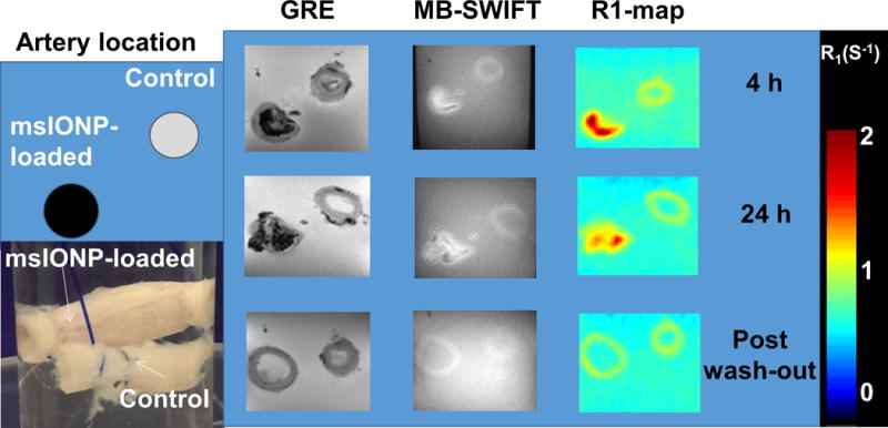
Schematic and photograph of arteries loaded with 1.0 mg Fe/mL of msIONP compared to control (no msIONPs) in VS55 at room temperature during loading and washout (N = 2, n = 2). GRE and SWIFT MR images were acquired and the R1 map was generated from the SWIFT data. The color bar indicates the R1 in 1/s. Images were taken at 4 and 24 h after msIONP loading and post washout.
Biomechanical assessment
Stress-strain curves were acquired to examine the impact of nanowarming on tissue biomechanics (Fig. 7A). A representative stress-strain curve is shown in Fig. 7B. Once nanowarmed, the tissue’s biomechanical parameters remained unchanged from fast convective warming (1 mL) and control, while the slow warmed samples showed a lower elastic modulus, toe region and longer initial length (Fig. 7C, table S3 and table S4). No statistically significant weight gain or loss was measured from any of the treatments (fig. S10). We noted a reduction in biomechanical parameters for slow warmed samples that corresponded with structural change and possible delamination as shown in the histology (Fig. 5B slow warmed).
Fig. 7. Nanowarming maintains biomechanical properties of porcine carotid arteries.
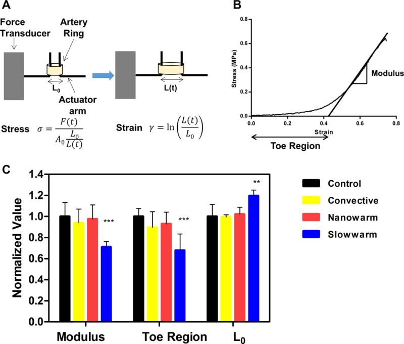
Arterial rings tested were taken from control (fresh artery) or from tissue that had been vitrified and convectively rewarmed, nanowarmed, or slow warmed. (A) Schematic illustrating how the biomechanical testing was conducted. Arteries were pulled in circumferential direction at a rate of 2 mm/min. The stress and strain was calculated by the equations shown in the figure, where F is the force measured at time t, A0 is the initial cross sectional area of the artery ring, L0 is the initial length of the artery, L(t) is the displacement at time t. (B) Representative stress strain curve. Elastic modulus is defined as the slope of linear region of the stress versus strain curve. The toe region is defined as the x-intercept of the stress versus strain curve. (C) Biomechanical properties of the rewarmed samples compared with fresh controls. All biomechanical properties of the rewarmed samples were normalized to control, which are fresh artery rings dissected from the same carotid artery to minimize the variances between the donor pigs. Red bars represent nanowarmed samples (elastic modulus = 98 ± 13%, toe region = 93 ± 11%, L0 =102 ± 7%), yellow bars represent convective warmed samples (elastic modulus = 94 ± 13%, toe region = 90 ± 15%, L0 = 99 ± 2%), blue bars represent slow warmed samples (elastic modulus = 71 ± 5%, toe region = 68 ± 16%, L0 =120 ± 6%). All data is presented as the mean ± standard deviation from n = 4 − 7 samples from N = 2 pigs for each condition.
Discussion
Cryopreservation is one of the few technologies for long-term storage of biomaterials (8–10). Of the cryopreservation approaches available, vitrification is an increasingly attractive approach that allows ice-free storage of biomaterials, potentially indefinitely. Vitrification has successfully preserved embryos, oocytes and stem cells (11–13). Unfortunately, at the tissue level, rates of cooling and warming in excess of 10 and 80 °C/min, respectively, are only feasible in volumes ≤ 3 mL at vitrification solution concentrations of 6 to 8 M, as reported by others (24) and shown in table S2. In short, convective cooling of VS55 can achieve vitrification in volumes larger than 1 mL; however, only fast convective warming of ≤ 3 mL VS55 vials is predicted to be successful without failure. Thus, while we can vitrify and occasionally rewarm roughly 15 g rabbit kidneys (17), and we can physically vitrify and rewarm in 80 mL systems, we do not have the technology to reproducibly rewarm these systems at sufficiently quick and uniform rates to avoid failure by devitrification and/or cracking using convection alone.
The nanowarming technology demonstrated here couples inductive low RF alternating magnetic fields with biocompatible msIONPs to create sufficient heating within 1 to 80 mL samples to uniformly exceed the CWR in VS55 systems. Specifically, nanowarming allows alternating magnetic fields to uniformly penetrate tissues with negligible attenuation and specific coupling to msIONPs deployed within the vitrification solution as previously demonstrated in a purely physical study (3). This differs from previous attempts to rewarm bulk tissues with RF electric field warming where coupling of the electric fields to the tissue with variable di-electric properties can lead to hot spots and thermal runaway (3). Fortunately, recent advances in production of biocompatible msIONPs with robust SAR in complex electrolyte solutions, protein media and biological tissues (19), along with the availability of larger inductive RF systems (27), now allows nanowarming to move from physical (1 mL) (3) to biological and functional demonstration in 1 to 50 mL volumes. Indeed, we have now demonstrated the benefits of nanowarming on numerous biological systems including HDF cells, porcine carotid arteries, porcine heart valves, and porcine femoral arteries in 1 mL and 50 mL systems. We have also demonstrated physical scale up to 50 and 80 mL systems.
Although, nanoparticles are reported to affect the behavior of devitrification and recrystallization of CPAs (28), these effects are typically at very low concentrations of solute as opposed to very high concentrations used in our approach. We have previously performed differential scanning calorimetry on these solutions and found no difference in the thermal properties including nucleation in VS55 alone and with IONPs (3). Moreover, the low frequency of these fields (100 − 400 kHz) is biocompatible (29) and confirmed by the viability test of HDFs in the operating RF coil. Finally, modeling suggests a future benefit of nanowarming can be the proactive design and implementation of non-linear warming rates and annealing step(s), thereby reducing or compensating for thermal stress buildup from cooling or warming that otherwise would lead to crack failure in bulk vitrified systems (4).
In order to take full advantage of nanowarming, loading of both the CPA and the msIONPs into the tissue without toxicity is required. The literature shows that VS55 and M22 can be loaded into tissues and organs without significant toxicity by using careful multi-step protocols at low temperatures (15, 17, 30). Following one such protocol demonstrated negligible toxicity in cells and tissues (porcine arteries and heart valve leaflets) as shown in Figs. 5 and S5 and reported previously (24). Further, we showed that the addition of 1 to 10 mg Fe/mL VS55 had no further impact on viability (P < 0.05). In addition, previous data demonstrated that the msIONPs are nontoxic when cultured with HDF over time at low concentration (0.07 mg Fe/mL) (19), and when injected at higher concentration (20 mg Fe/mL in 200 μL) intravenously into mice (31). This biocompatibility is due to both the mesoporous silica coating and the PEG bound to it as described previously (19). We also demonstrated the ability of VS55 to load and vitrify these tissues using μCT based on HU measurement. Finally, by using several MRI sequences we monitored both the loading and unloading of msIONPs in a porcine carotid artery as shown in Fig. 6 and reported previously for other systems (25).
To show the potential of nanowarming, we used several tissues and volume systems from 1 to 80 mL. We began with porcine carotid arteries and heart valves and established that we could match the viability and biomechanical assessments from gold standard fast convective warming in 1 mL systems. We demonstrated nanowarming success and convective failure for artery systems vitrified in 50 mL systems. Finally, we demonstrated physical nanowarming at 120 °C/min in both 50 and 80 mL systems, where the convective approach failed due to cracking and devitrification. For instance, during nanowarming of 50 mL systems warming rates ≥ 130 °C/min and stress of only 0.26 MPa (<σyield = 3.2 MPa) allow warming without devitrification and cracking (fig. S6B and F). On the other hand, during convective warming rates in the center are < 25 °C/min (fig S6C), which is < CWR for VS55 and will result in devitrification (table S1). Further, thermal gradients between the center and edge of the vial yield thermal stress roughly at the yield stress (3.16 MPa) which can potentially result in cracking (fig. S6D). Not surprisingly, the nanowarmed sample did not devitrify or crack, while the convectively rewarmed sample both crystallized and cracked. These cooling and warming rates match well with the modeling predictions in table S2 and Fig. 4. In short, nanowarming matches fast convective warming viability and biomechanical testing at 1 mL, is superior to convective warming at 50 mL, and is physically scalable to 80 mL systems.
In the future, we believe nanowarming can be applied to larger tissues and organs up to volumes of 1 L and possibly beyond. These larger volumes will require introduction of the nanoparticles directly into the tissue by perfusion to distribute the heat generation sufficiently. This can be advanced through modification of existing perfusion methods, such as those already in existence for kidneys (17). Indeed, other new approaches suggest that livers can be perfused with CPA and be pre-conditioned to better withstand hypothermic preservation (32). However, during perfusion only the vascular space, which constitutes roughly 10% of most tissues, will be available to these nanoparticles. Nevertheless, 4 mg Fe/ml msIONPs in M22 is able to warm at 55 °C/min which far exceeds its CWR. As rabbit kidneys have been successfully vitrified with loaded M22 (17) and we have demonstrated physical nanowarming to 80 mL, we believe that consistent nanowarming of rabbit kidneys with retention of function should be feasible. Further, an 80 mL system should also be sufficient for human liver cores that could greatly improve throughput for existing cryopreservation methods of precision cut liver slices (33).
To contemplate further scale up to vascularized composite allografts or whole livers, coil systems ≥ 1 L will be needed (8). Indeed, systems with power as high as 150 kW are commercially available to drive such coils (Fluxtrol). However, as these coils increase in size so will the eddy currents – the non-homogeneity in the fields – which can rise above 10% of the desired SAR in 80 mL vials with radius ≥ 2.5 cm. While this suggests non-uniformity in heating radially, it also suggests an opportunity to engineer the heating by msIONPs addition to the organ, and reduced msIONPs – more eddy current heating – in the surrounding system. Further efforts to model the nanowarming process to account for these effects and ensuing thermal stress are underway (4). With continued breakthroughs in pre- and/or post- conditioning of organs (32), improved perfusion and vitrification protocols (17), and other enabling technologies that are being brought to bear to successfully vitrify human organs (8), we believe that nanowarming can converge with and enable these technologies to help make organ cryopreservation a reality.
Materials and Methods
Study design
The objective of this study was to evaluate the efficacy of nanowarming technology as a method of tissue rewarming after vitrification compared to the gold standard, convective rewarming. We first nanowarmed HDF cells as a proof of principle and then extended our evaluation to two cardiovascular tissue models, porcine artery and aortic heart valve leaflet tissues in 1 and 50 mL systems. We demonstrated physical scale up without tissue cracking or devitrification failure in up to 80 mL systems of cryoprotectant solution VS55. This scale up of tissue cryopreservation allows larger systems to be cryopreserved, and it is a critical and necessary first step towards future perfused tissue and organ work. Replicate numbers of each experiment are included in the figure captions. Tissues were randomized from N pigs and n vessels or tissues total. The histology images were qualitatively ranked by a pathologist blinded to the study. Outliers, such as samples that cracked due to exterior mechanical stress – for example, due to manipulation with tweezers – were not considered within the data. Primary data are reported in table S5.
Nanoparticle and VS55 synthesis
The synthesis of msIONPs follows our previous work where a mesoporous silica coating is synthesized around a core of IONPs (EMG308, Ferrotec) (19). VS55 is an 8.4 M cryopreservation solution of 2.2 M propylene glycol (Sigma Aldrich), 3.1 M formamide (Sigma Aldrich), and 3.1 M dimethyl sulfoxide (Sigma Aldrich) in Euro-Collins (EC) solution made in the lab (15).
RF inductive rewarming
The vitrified samples were heated in 1 kW Hotshot inductive heating systems with 2.75-turn, water-cooled copper coil (Ameritherm Inc.) or a 15 kW custom built system (Fluxtrol) as shown in Fig. 4A, fig. S1, and the Supplementary Materials. The 1 kW system was operated at a magnetic field of 20 kA/m (peak, volume-averaged field strength) and 360 kHz (3). Higher fields up to 60 kA/m at 175 kHz were achieved on the 15 kW system as shown in fig. S1. Nanowarming rates from samples of interest were subtracted from controls (no msIONPs) to estimate the heating rate and SAR by the temperature rise method as previously reported (3).
μCT imaging
Samples were first scanned in a μCT imaging system (NIKON XT H 225), then reconstructed to correct for beam hardening and to improve accuracy (3D CT pro, Nikon Metrology), imported as unsigned 16-bit float images and post-processed (VGstudio Max 2.2), and finally analyzed with ImageJ Fiji (open source). Diffusion of VS55 into the artery wall at room temperature was measured at 10 time points, roughly every 18 min, over 3 h in two representative porcine arteries. A medium resolution scan of 60 μm pixel size yielding 15 data points across the 0.9 mm arterial wall of one artery was used for the image acquisition. Separate arteries (n = 3/case) were assessed for vitrification success or failure.
Tissue toxicity and nanowarming assessments
Porcine tissues were procured from male and female skeletally immature domestic Yorkshire cross farm pigs (65 – 80 kg, aged 16 – 18 weeks) postmortem from a meat processing plant (Burbage Meats, Ravenel, SC). The arteries were removed within 30 min of death following independent Institutional Animal Care and Use Committee approved research protocols by local IACUC at the Medical University of South Carolina and University of Minnesota. All tissues used were considered bonafide excess, so no animals were specifically euthanized for this research. Tissues were transported in a lab-made Krebs-Henseleit buffer to our lab. Fresh artery segments were rinsed with growth media [Dulbecco’s Modified Eagle Medium (DMEM, Thermo Fisher) with 1% Antibiotic-Antimycotic (Thermo Fisher)], and cleared of fatty tissue. For the 1 mL system, artery segments were sectioned into artery rings of the following reproducible dimensions: inner diameter: 3 − 4 mm; wall thickness: 1 − 2 mm, length: 3 − 5 mm. In the 50 mL experiments, carotid artery segments with the same inner diameters and thickness as in 1 mL system were used except with longer length (7 − 10 cm).
In 1 mL experiments, the artery rings were incubated with 10% alamarBlue (Thermo Fisher) media solution at 37 °C for 3 h before any rewarming experiments. Fluorescence was read on a plate reader (Synergy HT, BioTek) at 590 nm from an aliquot of the media to establish a baseline. The tissues were loaded following a previously published protocol (24). After the VS55 loading, on the last step (VS55 full strength exposure) the tissues were placed in 1 mL of 10 mg Fe/mL msIONPs VS55 suspension and exposed to cooling and rewarming procedures. All samples were successfully vitrified and stored in a liquid nitrogen storage Dewar overnight (19 – 22 h). Different rewarming procedures were attempted: nanowarming (20 kA/m, 360 kHz); fast convective warming (37 °C water bath immersion, which is the gold standard); intermediate rewarming on ice; and slow rewarming in a 6 cm cube of Styrofoam modified by drilling a hole for our 1 mL vial. After the removal of the VS55, the post-treatment tissues were incubated with alamarBlue. The viability of each tissue piece was calculated by comparing the fluorescence readings before and after cooling and rewarming and normalized to fresh control. Further cell damage, morphological, structural and DNA damage post cooling/rewarming were assessed by H&E and TUNEL stain. The histology samples were prepared immediately after removal of msIONPs and VS55. In 50 mL experiments, the control artery sections were incubated with 10% alamarBlue media solution at 37 °C for 3 h to obtain fresh untreated control viability. The tissues were loaded in steps as shown in fig S9. The nanowarming was achieved by using 15 kW RF system at 60 KA/m and 175 kHz. After the removal of the VS55 and msIONPs, the post treatment tissues were sectioned into small pieces and incubated with fresh media at 37 °C for 1 h and then incubated with 10% alamarBlue for 3 h. The viability of each tissue piece was calculated as in the 1 mL system.
MR − SWIFT imaging
All MR images were acquired on a 9.4 T 31 cm MRI scanner (Agilent Technologies) with software designed for pre-clinical MR imaging research (Vnmrj, Agilent Technologies). A custom three-loop volume coil was used. Both 3D multi-band SWIFT (MB-SWIFT) and 3D gradient echo (GRE) images were acquired (25). MR imaging was performed at 4 h and 24 h after loading and then unloading msIONPs from the lumen of an artery. The detailed methods are given in the Supplementary Materials and closely follow previous protocols (25).
Biomechanical testing of arteries
Porcine artery rings which underwent the freezing and thawing procedures were compared with measurements from fresh control artery rings to minimize the variance between tissues. Uniaxial tensile tests of artery rings were performed within 2 h post-rewarming and unloading of the artery rings on an MTS Micro-Bionix testing machine (MTS systems,) using a previously reported protocol (26). The biomechanical response was quantified by toe region and elastic modulus that was obtained from stress vs. strain curves as previously described on pre-conditioned samples (26).
Thermal and mechanical response in cylindrical systems
We modeled the heat transfer using the energy equation below to calculate temperature response in a one-dimensional infinite cylinder with variable radius from 0.5 to 2.5 cm as shown in Fig. 4:
| (1) |
All boundary conditions and parameters for this analysis are listed in Supplementary Materials section with specific results reported in table S2.
For calculation of thermal stress, the maximum temperature difference between the centerline and the edge of the cylinder, ΔTmax, is considered below the so-called set temperature of VS55 (−105 ˚C). This temperature gradient in turn produces thermal stress which was approximated based on a simplified “thermal shock-equation” (below), following (18) and described further in table S2:
| (2) |
where σT is the thermal stress, g is a geometric coefficient (0.5 for cylindrical geometry), E is the modulus of elasticity (estimated at 1 GPa), β is the linear coefficient of thermal expansion is the Poisson’s ratio and ΔT is the thermal gradient from the heat transfer calculation. All parameters for this analysis are listed in Supplemental Methods Section with specific results reported in table S2.
Statistical analysis
All the viability, biomechanical and histology (white space) analysis data were normalized to controls. These data are reported in the figure captions and all possible multiple comparisons are shown in table S3 and table S4. For brevity, the P values, but not the numerical data values, are reported in the results, although numerical data and error bars are given in the captions. Statistical significance and exact P values are reported in table S4 and some of the figure captions. In general, statistical significance compared with fresh samples in the figures themselves is indicated with asterisks: * P < 0.05; ** P < 0.01; *** P < 0.001 **** P < 0.0001. The data is presented as the mean with standard deviation. The one-way analysis of variance (ANOVA) with Tukey’s multiple comparison tests (GraphPad Prism, GraphPad Software, Inc.) was performed on control and treated samples’ viability and biomechanical properties in different conditions. Two-tailed T test was performed on the analysis of area in histology images.
Supplementary Material
Acknowledgments
We thank the Visible Heart Lab’s Charles Soule, Alex Deakyne and Tinen Healy for access to porcine arteries, Connie Chung for help with initial cell culture experiments, Yung-Chung Chen for setting up the μCT and Shaunak Phatak for help with modeling of cylindrical cooling. We also thank University of Minnesota Characterization Facility, Imaging Center and Histology and IHC Laboratory for their technical assistances.
Funding: This work was supported by a MN Futures grant (UM) to CLH, JCB and MG, NSF/CBET 1336659 and the Kuhrmeyer Chair to JCB, and NIH P41EB015894 to MG, the US Army Medical Research and Materiel Command under Contract No.W81XWH-15-C-0173 and NIH R43HL123317 to KGMB. The views, opinions and findings contained in this report are those of the authors and should not be construed as an official National Institutes of Health or Department of the Army position, policy or decision unless so designated by other documentation.
Footnotes
Author contributions: NM and ZG conceived experiments with analysis and support from JCB and KGMB. ZG and QS performed cell work. ZG and NM performed tissue work. MMD and ZG synthesized the msIONPs. NM, YR, FL and JCB performed and/or analyzed the heating experiments and thermal and mechanical modeling. JZ, NM and HLR performed SWIFT imaging and JZ analyzed the images. NM and AF performed and analyzed the μCT experiments. JCB, KGMB, MG, AF and CLH oversaw the project. NM and ZG wrote the manuscript with support and input from all the authors.
Materials and Methods
Fig. S1. Nanowarming scale up in field and system size.
Fig. S2. Nanowarming of cells.
Fig. S3. Viability of carotid artery rewarmed on ice.
Fig. S4. Quantitative analysis of H&E stained artery cross section.
Fig. S5. Impact of increased SAR on artery wall thickness.
Fig. S6. Characterization of nanowarming in 50 mL system.
Fig. S7. Viability assessment of rewarmed heart valve leaflets in 1 mL.
Fig. S8. Nanowarming of porcine femoral arteries in 50 mL system.
Fig. S9. Characterization of nanowarming in 80 mL system.
Fig. S10. Weight changes of artery rings before and after treatments.
Table S1. Properties of cryoprotectant vitrification solutions.
Table S2. Convective cooling and warming success and failure in cylindrical volumes.
Table S3. Normalized viability.
Table S4. P values for all significant findings.
Table S5. Primary data.
Competing interests: A Patent on the nanowarming technology has been published as US/2016/0015025, and is titled: “Cryopreservative compositions and methods” (J.C.B). The UM has also filed a patent for msIONPs under application number 14/811,490, and is titled: “Mesoporous Silica-Coated Nanoparticles” (C.L.H.).
Data and materials availability: All materials and data are as described in the methods, text and references.
References and Notes
- 1.Jain S, Hirst DG, O’Sullivan JM. Gold nanoparticles as novel agents for cancer therapy. The British Journal of Radiology. 2012;85:101–113. doi: 10.1259/bjr/59448833. [DOI] [PMC free article] [PubMed] [Google Scholar]
- 2.Kim BY, Rutka JT, Chan WC. Nanomedicine. New England Journal of Medicine. 2010;363:2434–2443. doi: 10.1056/NEJMra0912273. [DOI] [PubMed] [Google Scholar]
- 3.Etheridge ML, Xu Y, Rott L, Choi J, Glasmacher B, Bischof JC. RF heating of magnetic nanoparticles improves the thawing of cryopreserved biomaterials. Technology. 2014;2:229–242. [Google Scholar]
- 4.Eisenberg DP, Bischof JC, Rabin Y. Thermomechanical stress in cryopreservation via vitrification with nanoparticle heating as a stress-moderating effect. Journal of biomechanical engineering. 2016;138:011010. doi: 10.1115/1.4032053. [DOI] [PubMed] [Google Scholar]
- 5.Hirsch LR, Stafford R, Bankson J, Sershen S, Rivera B, Price R, Hazle J, Halas NJ, West J. Nanoshell-mediated near-infrared thermal therapy of tumors under magnetic resonance guidance. Proceedings of the National Academy of Sciences. 2003;100:13549–13554. doi: 10.1073/pnas.2232479100. [DOI] [PMC free article] [PubMed] [Google Scholar]
- 6.Thiesen B, Jordan A. Clinical applications of magnetic nanoparticles for hyperthermia. International journal of hyperthermia. 2008;24:467–474. doi: 10.1080/02656730802104757. [DOI] [PubMed] [Google Scholar]
- 7.Pankhurst Q, Thanh N, Jones S, Dobson J. Progress in applications of magnetic nanoparticles in biomedicine. Journal of Physics D: Applied Physics. 2009;42:224001. [Google Scholar]
- 8.Lewis JK, Bischof JC, Braslavsky I, Brockbank KG, Fahy GM, Fuller BJ, Rabin Y, Tocchio A, Woods EJ, Wowk BG, Acker JP, Giwa S. The grand challenges of organ banking: proceedings from the first global summit on complex tissue cryopreservation. Cryobiology. 2016;72:169–182. doi: 10.1016/j.cryobiol.2015.12.001. [DOI] [PubMed] [Google Scholar]
- 9.Mazur P. Freezing of living cells: mechanisms and implications. American Journal of Physiology-Cell Physiology. 1984;247:C125–C142. doi: 10.1152/ajpcell.1984.247.3.C125. [DOI] [PubMed] [Google Scholar]
- 10.Karlsson JO, Toner M. Long-term storage of tissues by cryopreservation: critical issues. Biomaterials. 1996;17:243–256. doi: 10.1016/0142-9612(96)85562-1. [DOI] [PubMed] [Google Scholar]
- 11.Rall WF, Fahy GM. Ice-free cryopreservation of mouse embryos at −196 degrees C by vitrification. Nature. 1985;313:573–575. doi: 10.1038/313573a0. [DOI] [PubMed] [Google Scholar]
- 12.He X, Park EY, Fowler A, Yarmush ML, Toner M. Vitrification by ultra-fast cooling at a low concentration of cryoprotectants in a quartz micro-capillary: a study using murine embryonic stem cells. Cryobiology. 2008;56:223–232. doi: 10.1016/j.cryobiol.2008.03.005. [DOI] [PMC free article] [PubMed] [Google Scholar]
- 13.Jin B, Kleinhans F, Mazur P. Survivals of mouse oocytes approach 100% after vitrification in 3-fold diluted media and ultra-rapid warming by an IR laser pulse. Cryobiology. 2014;68:419–430. doi: 10.1016/j.cryobiol.2014.03.005. [DOI] [PMC free article] [PubMed] [Google Scholar]
- 14.Pegg D. Principles of cryopreservation. Methods Mol Biol. 2007;368:39–57. doi: 10.1007/978-1-59745-362-2_3. [DOI] [PubMed] [Google Scholar]
- 15.Brockbank KGM, Chen Z, Greene ED, Campbell LH. In: Cryopreservation and Freeze-Drying Protocols. Wolkers FW, Oldenhof H, editors. Springer New York; New York, NY: 2015. pp. 399–421. chap. Vitrification of Heart Valve Tissues. [Google Scholar]
- 16.Mehl PM. Nucleation and crystal growth in a vitrification solution tested for organ cryopreservation by vitrification. Cryobiology. 1993;30:509–518. doi: 10.1006/cryo.1993.1051. [DOI] [PubMed] [Google Scholar]
- 17.Fahy GM, Wowk B, Pagotan R, Chang A, Phan J, Thomson B, Phan L. Physical and biological aspects of renal vitrification. Organogenesis. 2009;5:167–175. doi: 10.4161/org.5.3.9974. [DOI] [PMC free article] [PubMed] [Google Scholar]
- 18.Steif PS, Palastro MC, Rabin Y. The effect of temperature gradients on stress development during cryopreservation via vitrification. Cell preservation technology. 2007;5:104–115. doi: 10.1089/cpt.2007.9994. [DOI] [PMC free article] [PubMed] [Google Scholar]
- 19.Hurley KR, Ring HL, Etheridge M, Zhang J, Gao Z, Shao Q, Klein ND, Szlag VM, Chung C, Reineke TM, Garwood M, Bischof JC, Haynes CL. Predictable heating and positive MRI contrast from a mesoporous silica-coated iron oxide nanoparticle. Molecular pharmaceutics. 2016;13:2172–2183. doi: 10.1021/acs.molpharmaceut.5b00866. [DOI] [PubMed] [Google Scholar]
- 20.Etheridge ML, Hurley KR, Zhang J, Jeon S, Ring HL, Hogan C, Haynes CL, Garwood M, Bischof JC. Accounting for biological aggregation in heating and imaging of magnetic nanoparticles. Technology. 2014;2:214–228. doi: 10.1142/S2339547814500198. [DOI] [PMC free article] [PubMed] [Google Scholar]
- 21.Jeon S, Hurley KR, Bischof JC, Haynes CL, Hogan CJ. Quantifying intra-and extracellular aggregation of iron oxide nanoparticles and its influence on specific absorption rate. Nanoscale. 2016;8:16053–16064. doi: 10.1039/c6nr04042j. [DOI] [PubMed] [Google Scholar]
- 22.Freitas C, Müller RH. Effect of light and temperature on zeta potential and physical stability in solid lipid nanoparticle (SLN™) dispersions. International journal of pharmaceutics. 1998;168:221–229. [Google Scholar]
- 23.Bischof JC, Mahr B, Choi JH, Behling M, Mewes D. Use of X-ray tomography to map crystalline and amorphous phases in frozen biomaterials. Annals of biomedical engineering. 2007;35:292–304. doi: 10.1007/s10439-006-9176-7. [DOI] [PubMed] [Google Scholar]
- 24.Baicu S, Taylor M, Chen Z, Rabin Y. Vitrification of carotid artery segments: an integrated study of thermophysical events and functional recovery toward scale-up for clinical applications. Cell preservation technology. 2006;4:236–244. doi: 10.1089/cpt.2006.9994. [DOI] [PMC free article] [PubMed] [Google Scholar]
- 25.Zhang J, Chamberlain R, Etheridge M, Idiyatullin D, Corum C, Bischof J, Garwood M. Quantifying iron-oxide nanoparticles at high concentration based on longitudinal relaxation using a three-dimensional SWIFT Look-Locker sequence. Magn Reson Med. 2014;71:1982–1988. doi: 10.1002/mrm.25181. [DOI] [PMC free article] [PubMed] [Google Scholar]
- 26.Venkatasubramanian RT, Wolkers WF, Shenoi MM, Barocas VH, Lafontaine D, Soule CL, Iaizzo PA, Bischof JC. Freeze-thaw induced biomechanical changes in arteries: role of collagen matrix and smooth muscle cells. Annals of biomedical engineering. 2010;38:694–706. doi: 10.1007/s10439-010-9921-9. [DOI] [PubMed] [Google Scholar]
- 27.Bordelon DE, Goldstein RC, Nemkov VS, Kumar A, Jackowski JK, DeWeese TL, Ivkov R. Modified solenoid coil that efficiently produces high amplitude AC magnetic fields with enhanced uniformity for biomedical applications. Magnetics, IEEE Transactions. 2012;48:47–52. doi: 10.1109/TMAG.2011.2162527. [DOI] [PMC free article] [PubMed] [Google Scholar]
- 28.Han X, Ma H, Wilson C, Critser J. Effects of nanoparticles on the nucleation and devitrification temperatures of polyol cryoprotectant solutions. Microfluidics and nanofluidics. 2008;4:357–361. [Google Scholar]
- 29.Foster KR. Thermal and nonthermal mechanisms of interaction of radio-frequency energy with biological systems. IEEE Transactions on Plasma Science. 2000;28:15–23. [Google Scholar]
- 30.Fahy GM, MacFarlane DR, Angell CA, Meryman HT. Vitrification as an approach to cryopreservation. Cryobiology. 1984;21:407–426. doi: 10.1016/0011-2240(84)90079-8. [DOI] [PubMed] [Google Scholar]
- 31.Zhang J, Ring HL, Hurley KR, Shao Q, Carlson CS, Idiyatullin D, Manuchehrabadi N, Hoopes PJ, Haynes CL, Bischof JC. Quantification and biodistribution of iron oxide nanoparticles in the primary clearance organs of mice using T1 contrast for heating. Magnetic Resonance in Medicine. 2016 doi: 10.1002/mrm.26394. in press. [DOI] [PMC free article] [PubMed] [Google Scholar]
- 32.Berendsen TA, Bruinsma BG, Puts CF, Saeidi N, Usta OB, Uygun BE, Izamis ML, Toner M, Yarmush ML, Uygun K. Supercooling enables long-term transplantation survival following 4 days of liver preservation. Nature medicine. 2014;20:790–793. doi: 10.1038/nm.3588. [DOI] [PMC free article] [PubMed] [Google Scholar]
- 33.Fahy GM, Guan N, de Graaf IA, Tan Y, Griffin L, Groothuis GM. Cryopreservation of precision-cut tissue slices. Xenobiotica. 2013;43:113–132. doi: 10.3109/00498254.2012.728300. [DOI] [PubMed] [Google Scholar]
Associated Data
This section collects any data citations, data availability statements, or supplementary materials included in this article.