

Abstract
Owls are known for their outstanding neck mobility: these birds can rotate their heads more than 270°. The anatomical basis of this extraordinary neck rotation ability is not well understood. We used X‐ray fluoroscopy of living owls as well as forced neck rotations in dead specimens and computer tomographic (CT) reconstructions to study how the individual cervical joints contribute to head rotation in barn owls (Tyto furcata pratincola). The X‐ray data showed the natural posture of the neck, and the reconstructions of the CT‐scans provided the shapes of the individual vertebrae. Joint mobility was analyzed in a spherical coordinate system. The rotational capability was described as rotation about the yaw and roll axes. The analyses suggest a functional division of the cervical spine into several regions. Most importantly, an upper region shows high rolling and yawing capabilities. The mobility of the lower, more horizontally oriented joints of the cervical spine is restricted mainly to the roll axis. These rolling movements lead to lateral bending, effectively resulting in a side shift of the head compared with the trunk during large rotations. The joints in the middle of the cervical spine proved to contribute less to head rotation. The analysis of joint mobility demonstrated how owls might maximize horizontal head rotation by a specific and variable combination of yawing and rolling in functionally diverse regions of the neck.
Keywords: cervical joints, cervical vertebrae, head mobility, spine, Tyto
Introduction
Owls (Strigiformes) are famous for their outstanding neck mobility (Fig. 1). Head rotations of 270° to the left and right are possible (Walls, 1963; Steinbach & Money, 1973; de Kok‐Mercado et al. 2013). The extraordinary neck mobility may be regarded as a key adaptation of owls, because it enables these birds to effectively use other physiological adaptations. For example, it helps to fixate prey with the almost immobile and frontally oriented eyes (Steinbach & Money, 1973; van der Willigen et al. 2002), and it improves auditory detection with the frontally oriented ruff (Payne, 1971; Mebs & Scherzinger, 2000; Hausmann et al. 2009). The neck is involved in every orienting movement of the owl towards a sensory stimulus (Ohayon et al. 2006). Despite its important function in orienting, we have only just begun to understand the morphology of the owl neck (Boas, 1929; Krings et al. 2014; Boumans et al. 2015).
Figure 1.
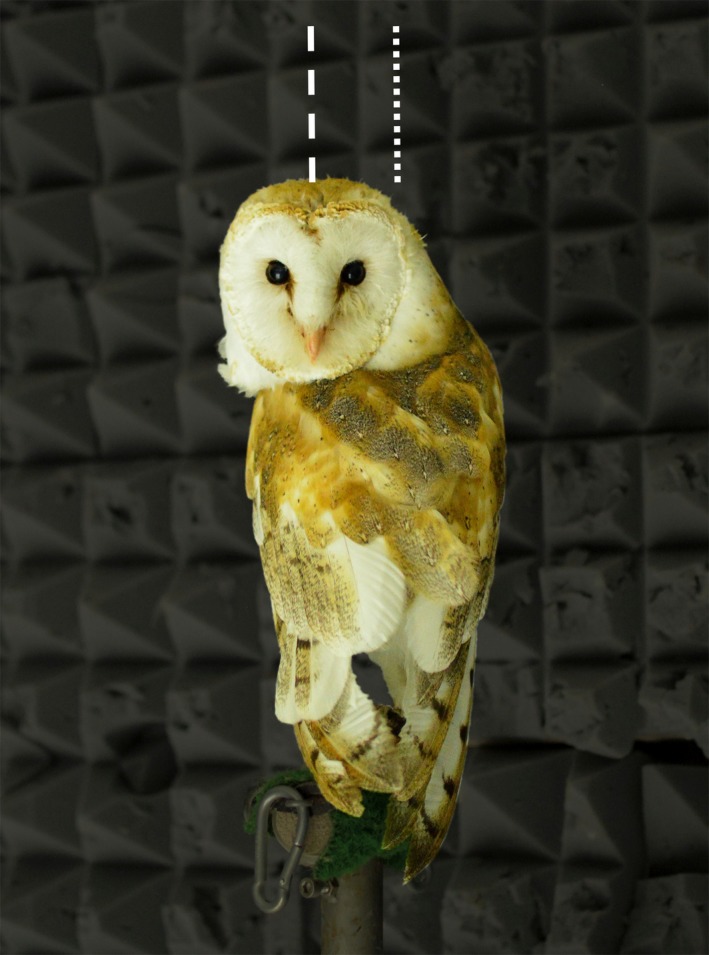
Barn owl showing a natural head rotation. Photo of owl W from our breeding colony. The bird turns the head to the left by about 180°. The extension of the middle of the head is marked by the dashed line, and the extension of the middle of the trunk is marked by the dotted line. Note the shifting of the head to the left. Photo by Kerstin Doerenkamp.
The forelimbs of birds are adapted for flight and underlie multiple constraints. Therefore, the beak has to take over functions of the forelimbs. For example, the beak has to reach every feather at the body to allow appropriate plumage care (Stark, 1979). Owls have an outstanding head‐rotation capability (Grytsyshina et al. 2016). This makes owls an interesting study case for neck mobility. The neck of the American barn owl (Tyto furcata pratincola) is S‐shaped (Krings et al. 2014) as is common for birds (Owen, 1866; Boas, 1929; Tambussi et al. 2012). It is composed of 14 cervical vertebrae (Krings et al. 2014). The vertebral bodies are connected by joints (Landolt & Zweers, 1985; see Krings et al. 2014 for data of the barn owl). The first cervical vertebra, called the atlas, forms a ball and socket joint with the occipital complex of the skull. Mobility at this joint is larger in birds than in mammals because birds, except for the hornbills (Kaiser, 2007), have only one atlanto‐occipital articulation, whereas mammals have two. The atlas forms a pivot joint with a cranially protruding dens of the second cervical vertebra, called the axis. This pivot joint favors yaw movements. All other cervical joints are heterocoelous or saddle‐shaped joints. Krings et al. (2014) found a regionalization within the 14 cervical vertebrae similar to that already observed by Boas (1929). However, the cluster analysis performed by Krings et al. (2014) suggested up to seven separable regions in the cervical spine, much more than the three reported by Boas (1929). The regionalization proposed by Krings et al. (2014) was based on morphological characteristics of the cervical vertebrae that are thought to influence neck mobility. One criterion was the diameter of the central canal; a second criterion was the length of the zygapophyseal protrusion. Wide central canals provide room for movements of the spinal cord during large neck rotations. Thus, wide central canals should occur in highly mobile regions. Indeed, de Kok‐Mercado et al. (2013) observed that the transverse canals of the cervical vertebrae are approximately 10 times bigger than the arteries crossing them, which protects the arteries from being squeezed. Long zygapophyses are expected to restrict joint mobility about the yaw and roll axes (for a definition of the coordinate system see Fig. 2), because they cause an overlap of a given vertebra with the neighboring vertebra. The zygapophyses form synovial joints, which are important for neck mobility. In these joints the parallel joint facets slide against each other (Landolt & Zweers, 1985; Kaiser, 2007). The study by Krings et al. (2014) demonstrated that the upper and lower regions of the cervical spine were characterized by wide central canals and short zygapophyses, whereas the middle region showed narrow central canals and big zygapophyseal protrusions.
Figure 2.
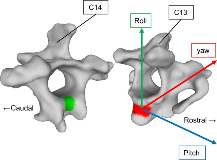
The disarticulated cervical vertebrae C13 and C14 with their joint facets and the coordinate system used for analysis. The green facet is responsible for pitching, the red facet for rolling. The coordinate system used for analysis is positioned in the center of the red convex surface and was found using a sphere. Its rolling axis points towards the vertebral arch of the rostral vertebra (C13). Modified after Krings et al. (2014).
Given the aforementioned morphological characteristics, we deduced a hypothesis for the rotational capabilities: large head rotations to the left and right should occur mainly in the upper and lower parts of the cervical spine. The S‐shaped form of the owl neck led to a specification of the hypothesis: the movement in the more horizontal lower part should be a rolling movement, whereas the more vertical upper part should perform a yaw movement. To test this hypothesis, we recorded X‐ray movies of neck rotations in living birds. Moreover, we measured forced neck rotations in carcasses and analyzed the mobility of each joint with local coordinate systems in a three‐dimensional micro‐CT based model of the barn owl neck (individual analysis). Finally we used this model to measure the impact of each joint on a horizontal head rotation in an external coordinate system (combined analysis).
Methods
Eight American barn owls (Tyto furcata pratincola, Temmink 1828, formerly Tyto alba pratincola, Bonaparte 1838) from the breeding colony of the Institute of Biology II at RWTH Aachen University (Aachen, Germany) were used in this study. The specimens were characterized by their name (initial), sex, age at time of experiment, and their condition [alive (*) or dead (†)]: E, sex unknown, 9 months, †; G, ♀, 11 years, †; H, ♀, 3 years, †; L, ♂, 14 years, †; T, ♀, 2 years, *; W, ♂, 15 years, *; X, ♂, 2 years, †; Y, ♂, 11 years, †). Carcasses used in this investigation were from animals that died a natural death or were sacrificed at the end of other projects. Care and treatment of the owls was in accordance with the NIH Guide for the use and care of laboratory animals. All procedures strictly adhered to pertinent regulations and were approved by the responsible authorities of the states of North Rhine‐Westphalia and Thuringia, Germany. Some of the barn owls had a metal bar (head holder) on the skull that was fixed to the bone with dental cement. Surgery was performed under ketamine/diazepam‐anesthesia (for more information see Vonderschen & Wagner (2012)).
X‐ray fluoroscopy
To visualize, animate and analyze large neck rotations of two barn owls (owls H, T), we used X‐ray motion analysis. The animals were placed in a biplanar, high‐frequency X‐ray fluoroscopy setup (Neurostar, Siemens, Munich, Germany) at Friedrich‐Schiller‐University in Jena. We induced neck rotations by drawing the attention of the animals to food or other items. Spontaneously occurring rotations were recorded as well. Non‐invasive, markerless quantification of intervertebral three‐dimensional (3D) movements had been successfully achieved for mammals using the same X‐ray system (Nyakatura & Fischer, 2010; Wachs et al. 2016). Nevertheless, quantitative analysis was not possible here because of the small size of the vertebrae. As a consequence, the resolution of the X‐ray fluoroscopy did not allow for precise measurements, e.g. of the very small intervertebral distances and the movements. The films were undistorted and calibrated using matlab scripts (MathWorks, Natick, MA, USA) developed by the XROMM group (Brown University, Providence, RI, USA). Details of X‐ray fluoroscopy aspects of the current study were reported in a previous publication (Krings et al. 2014).
Forced neck rotations in carcasses
We took three barn owl carcasses (owls G, L, X) and removed the feathers and the skin at the head, the neck and the thorax (Fig. 3). The dead bird was positioned on a table on the back so that the beak was pointing upwards. In this position, the neck was stretched so that it approximated a straight line. A forced rotation was applied to these carcasses. This was done by three authors independently (M.K., H.W., M.B.). The aim was to turn the head to the maximum angle possible without rupturing muscles or ligaments. Although this treatment created an artificial situation, it yielded important insights into the movements possible during large head rotations.
Figure 3.
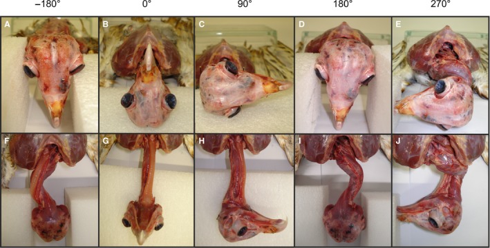
Forced neck rotations in carcasses. The rotated head and neck of owl E are shown in a cranial view (A–E) and a ventral view (F–J). Feathers and skin were removed. Note the excursion of the lower part of the neck to the left (E), and to the right (I and J).
CT reconstructions
We obtained micro‐CT scans of all neck vertebrae, the occipital complex and the first thoracic vertebra of two dead barn owls (owls H, Y). All bones were dissected and isolated before the scans were obtained. Scans (v|tome|x s, GE phoenix|x‐ray, Wunstorf, Germany) were conducted at the Rheinische Friedrich‐Wilhelms‐Universität in Bonn, Germany. The software amira ® (Mercury system, Chelmsford, MA, USA) and the software meshlab ® (ISTI‐CNR, Pisa, Italy) were used for reconstruction. For further information see Krings et al. (2014).
For the reconstruction of a movable neck model, we used a step‐by‐step system. (i) Bringing the neck in a natural position: For each animal, we first determined an average neck posture from 20 natural postures, found in still images taken from X‐ray movies. This average neck posture was then used to align the bones in their S‐shaped arrangement in the animation software maya ® (Autodesk, San Raphael, CA, USA). (ii) Positioning of a left‐handed Cartesian coordinate system: Most intervertebral joints are saddle‐shaped with two opposing convex–concave surfaces. Moreover, saddle‐shaped joints are biaxial. The curvatures of the surfaces are arranged in different body axes. The curvature of the caudal surface was extended in the roll axis and could, therefore, support pitching (green surface in Fig. 2). By contrast, the curvature of the rostral surface was extended in the pitch axis and could, therefore, support rolling (red surface in Fig. 2). However, the position of the center of yawing could not be inferred in a similar way. Our X‐ray films revealed pitching to play a minor role in large neck rotations. As a consequence, we focused on yawing and rolling in our later mobility analyses and decided to use the same coordinate system for both rotations. The rotation center was identified as the center of a sphere fitted to the rostral convex surface. The coordinate system was positioned in the center of this sphere. (iii) Orientation of the left‐handed Cartesian coordinate system: the rolling axis pointed towards the caudal rim of the cervical arch of the rostral vertebra. Apart from this, pitching movements were only added in the combined analysis for corrections of head position using a parallel coordinate system in the center of the caudal convex surface (not shown).
The intervertebral distances were determined according to Heidweiller (1989). We added the length of the vertebral bodies of the cervical vertebrae (owl H: 73.42 mm; owl Y: 69.25 mm). Heidweiller (1989) reported that this value makes up 95.5% of the length of the cervical spine, whereas the intervertebral space only makes up 4.5%. These data were used to calculate the intervertebral space: the result was 3.46 mm in owl H and 3.26 mm in owl Y. This corresponded to an average intervertebral distance of 0.27 mm for owl H and of 0.25 mm for owl Y. As in Heidweiller (1989), C1 and C2 were excluded from the measurement. Since this is a rather rough estimation, we decided to test two intervertebral distances that encompass the average distance. We chose 0.17 mm (intervertebral space about 3%) and 0.36 mm (intervertebral space about 6%).
Before we added the intervertebral distances to our model, we determined the minimum distance between the vertebrae. This was done in order to have a reproducible system. We used the yaw axis (Fig. 2) and translated the vertebrae in maya until they collided to obtain the minimum distance. The intervertebral distances were added along the yaw axis to this minimum distance to arrive at the required distance for each investigation.
Mobility in each joint
Testing the mobility in each joint, we called this analysis individual analysis (Fig. 4). Since pitching did not contribute to large neck rotations, rotations about the pitching axis (blue axis in Figs 2 and 4) were not applied. We measured the yawing (angle α) and rolling (angle β) capability in each joint. To do so, we performed two analyses, one starting with a roll movement followed by a yaw movement (rolling analysis), and a second starting with a yaw movement followed by a roll movement (yawing analysis). Each started with the average neck posture (Figs 4A and 5). In the rolling analysis, the joint was rotated on the roll axis in steps of 1° (Fig. 4B). If we faced collision of the two vertebrae involved (Fig. 4C), we corrected on the yaw axis (Fig. 4D). This procedure was continued until a correction could no longer be applied (Fig. 4E). In this way, we found the maximum roll angle with minimum yawing. The angles were called βr and αr, respectively. In the yawing analysis, we first rotated the joint about the yaw axis in steps of 1° and corrected on the roll axis to obtain the maximum yaw angle with minimum rolling. These angles were called αy and βy, respectively. Results of the two analyses were compared using a Wilcoxon matched‐pairs signed rank test (one‐sided test).
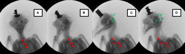
Figure 4.
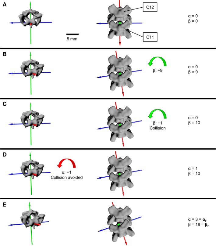
Rolling analysis for J11 in the 0.36 mm analysis of owl Y. Three anatomical axes define the joint. Rotation about the red axis is called yawing. The yawing angle is noted as α. Rotation about the green axis is called rolling. The rolling angle is noted as β. Rotation about the blue axis is called pitching. Pitching was excluded from the rotational analysis because no contribution of pitching to large neck rotations was observed. Pitching was only needed to keep head position upright, as seen in the movies. (A) Starting position. No rotation in the joint. (B) In the rolling analysis, the roll axis (green) was rotated first. We rotated about the roll axis in steps of 1°. We were able to execute nine rotational 1° steps, until in the 10th rotational step the vertebrae collided (C). (D) A correction of 1° about the yaw axis (red) avoided collision. (E) This procedure was continued until correction on the yaw axis could no longer avoid collision. In this way we found the maximum rolling angle (βr) with minimum yawing angle (αr).
Figure 5.
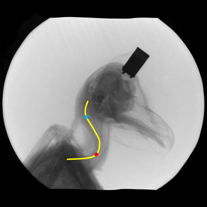
Snapshot from an X‐ray movie showing the S‐shape of the cervical spine of owl T. The cervical spine is composed of a horizontal lower part, an oblique middle part and a more vertical upper part. A yellow line indicates the S‐shape. The red and blue dots mark the flexion points between the lower and middle regions and the middle and upper regions, respectively. Modified after Krings et al. (2014).
Mobility of the whole neck
After the individual analysis, we added the rotations in each joint to measure the maximum horizontal rotational capability of the neck in an external coordinate system. This procedure is called ‘combined analysis’ in the following. The external coordinate system was centered on the owl's skull. For the single joints, we used the maximum angles from the individual analysis. The starting point was the lowermost joint from which we proceeded upwards, because the X‐ray movies showed that large neck rotations started at the lower joints. After each manipulation, we measured how far the head had rotated. Then we corrected the position of the head to keep it in a natural, straight position as much as possible, as seen in the movies. In these correction steps, pitching was also taken into account. Corrective movements were applied along the complete cervical spine, as necessary. Care was taken that the corrections did not change the horizontal head rotation. If the head could not be positioned upward with this procedure, we decreased the rotations and tried again. This was done until an upright head position could be reached. In this way it, sometimes, happened that maximum rotational angles as determined in the individual analysis had to be reduced in the combined analysis.
Results
Neck rotations as extracted from X‐ray fluoroscopy
The movies showed the natural neck posture of the barn owls. In a relaxed owl, the neck is in an S‐shaped posture with a more or less horizontal lower part, an oblique middle part and a vertical upper part (Fig. 5). The three parts execute different movements during large head rotations. The lower region showed predominantly rolling motions, which occurred mainly in the first part of large head rotations and led to a sidewise shifting of the head (Figs 1 and 6). Note the lateral shift of the head relative to the trunk in the photo shown in Fig. 1. The middle region remained relatively stiff, whereas the upper region showed mainly yawing movements.
Figure 6.
Sequence of snapshots made during head rotation. (A) At relative time t = 0 s, before the start of the rotation, owl T is looking towards the X‐ray source; the wing bones appear in an almost symmetrical position. (B) The bird has started to turn to the right (t = 0.7 s). (C) The turning movement has reached about 90° (t = 1.9 s). Note that the upper red point has moved to the left. (D) Further rotation (t = 4.2 s) leading to an increase of the distance between the two green points. The lower red point is positioned at the bifurcation of the furcula. The upper red point marks the flexion point between lower and middle regions (for the flexion points see Fig. 5). The horizontal distance between these landmarks is displayed as a red double arrow. Moreover, the distance between the center of the occipital bone (left/lower green point) and the rim of the skull (right/upper green point) is shown in the pictures (C) and (D) by means of a green double arrow. Note the circle surrounding the owl, which serves as a fixed external reference. A head holder (dark object) is fixed to the skull of the owl. The head holder also shows the rotation of the head.
For a more quantitative analysis, the bifurcation of the furcula was chosen as the lower reference point (lower red point in Fig. 6A), because this bone is distinctively linked to the thorax and is positioned at the base of the cervical spine. The second reference point (upper red point in Fig. 6A) marks the point on the cervical spine where the spine begins to bend backwards, i.e. the flexion point between the lower and middle part. Four snapshots from an X‐ray movie that capture the sequence of a typical neck rotation are shown in Fig. 6. In the beginning (Fig. 6A), the owl is facing the X‐ray source. The bones of the two wings and the frame of the body appear almost symmetrical. The beak faces directly into the X‐ray source. The two red dots show a small sideways shift (Fig. 6A). With the start of the head rotation to the right (in a coordinate system centered on the owl), the beak as seen from the point of view of the X‐ray source as it moves to the left (Fig. 6B). When the rotation exceeds about 45°, an increase of the horizontal distance between the two red dots becomes obvious (Fig. 6C). This shift between the red dots demonstrates that the lower part of the cervical spine performs a lateral bending. In terms of the rotation about the axes, it is a rolling movement. This rotation leads to a right shift of the head relative to the body.
In the last two images of the sequence, the distance between the center of the occipital complex and the rim of the skull was additionally marked in green (Fig. 6C). The distance between the green points increased between the last two frames. This proved that the skull had rotated (compare Fig. 6C with D). The upper part of the cervical spine could not be observed properly, but the middle part seemed to have rotated very slightly in the last two pictures (Fig. 6C,D). Consequently, the movement was located in the upper cervical spine. Because the axis of the upper cervical spine was a vertical one, the movement is a longitudinal axis rotation (yawing).
The sequence shown in Fig. 6 does not yield much information about what happens in the middle region of the cervical spine. However, this is not proof that there is no rotation in this part. Although the X‐ray recordings did not allow any quantitative analysis, we qualitatively got the impression that the middle region contributes relatively little to overall head rotation.
Forced neck rotations in carcasses
From the starting position (Fig. 3B,G) we turned the head either to the left or to the right to the maximum possible angle without rupturing muscles or ligaments. When the head was turned 90° in a clockwise direction (Fig. 3C), the neck remained more or less straight (Fig. 3H). This changed with further turning. After a rotation of 180° (Fig. 3D), which was easily possible, the neck had a curved appearance with an excursion of the lower part of the neck to the right (Fig. 3I). The opposite was observed when the head was turned by 180° in an anti‐clockwise direction (Fig. 3A,F). Now the curve made by the neck was to the left (Fig. 3F). We interpret these oppositional movements of the lower part of the neck as being equivalent to the lateral bending seen in the X‐ray movies (Fig. 6). Note that we fixed the skull relative to the trunk, whereas in natural neck rotation the head would move to the side relative to the trunk (Fig. 1). A forced rotation of 270° was easily possible (Fig. 3E). During very large head rotations, the neck started to curve even more, especially in the lower part and was drawn into the shoulders (Fig. 3J). It is unclear whether these forced rotations beyond 180° would occur in a similar manner in living animals.
These forced rotations were carried out in three dead barn owls. Rotations of more than 360° were possible in all three birds without rupturing muscles or ligaments.
Neck rotation models, based on vertebrae anatomy
Mobility in the single joints – the individual analysis
The maximum angles found in the yawing (αy, βy) and in the rolling analysis (αr, βr) are local maxima. The angles showed statistically significant differences, with αy being larger than αr and βr being larger than βy. The significance level was at least P < 0.005 in each of the eight analyses (two owls, two angles, two distances). We present αy and βr as results of the individual analyses (Figs 7 and 8). This procedure was chosen because we intended to demonstrate maximum possible yawing and maximum possible rolling in the cervical joints (for more information see Supporting Information Table S1).
Figure 7.
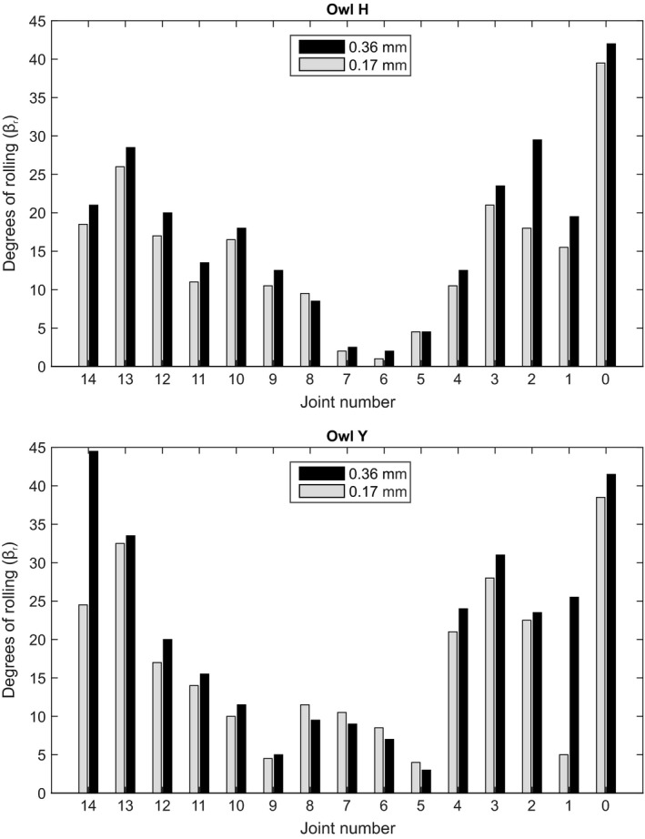
Rolling capabilities in each individual cervical joint of the barn owl neck. Maximum rolling was measured for two different intervertebral distances (0.17 and 0.36 mm).
Figure 8.
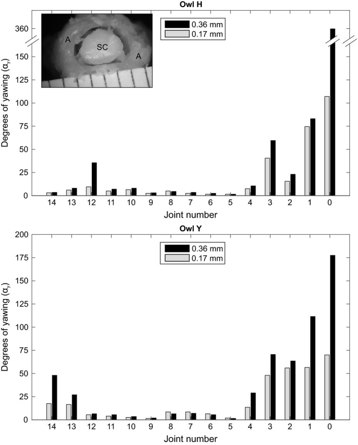
Yawing capabilities in each individual cervical joint of the barn owl neck. Maximum yawing was measured for two different intervertebral distances (0.17 and 0.36 mm). Inset: cross‐section of the cervical spine at the height of the atlas. This vertebra forms very mobile joints with the occipital bone and the axis, respectively. Note that the central canal of the atlas is much wider than the crossing spinal cord (for further information see Krings et al. 2014). A, atlas; SC, spinal cord.
The individual analysis showed that rolling ability was high in the lower and upper part of the cervical spine. The maximum rolling angle in joints (J) 10–14 and J0–J4 was higher than in the middle part (J5–J9) (Fig. 7). This held for both intervertebral distances tested. The maximum angles measured were around 40° (Fig. 7). In owl Y, two minima were observed, at J9 and J5. We interpret these minima to indicate the borders of the middle part. In owl H, only one minimum was detected. Nevertheless, also in this owl, rolling ability was low in the middle part and high in the lower and upper part of the cervical spine (Fig. 7).
Yawing ability was highest in the upper part of the cervical spine. In owl H the rotational capability of J0 was unlimited for a distance of 0.36 mm (for this, see next section). In both owls, yawing capability decreased towards J4 and was low for J5–J11. Some yawing ability occurred in the lower cervical spine. Generally, increasing the intervertebral distance influenced yawing capability of the upper cervical joints. This was especially true for J0 (Fig. 8). That high yawing capability did not influence the spinal cord, i.e. it did not cause a contusion, may be seen in the inset of Fig. 8. The diameter of the vertebral canal was much larger than the cross‐section of the spinal cord at this level.
Mobility in the whole neck – the combined analysis
To determine the cumulative maximum neck rotation, we used an external coordinate system in the combined analysis (Fig. 9). One restriction imposed in this analysis was that the head had to be oriented vertically (no rolling and no pitching of the head was allowed). The data of the combined analysis are presented as regression curves (Fig. 9). A fourth‐order polynomial was found to fit the data best and was, therefore, used to model the impact of each cervical joint on head rotation. The combined analysis also suggested a tripartition of rotational capability in the cervical spine.
Figure 9.
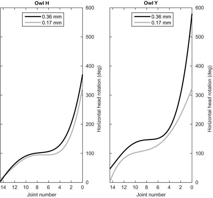
Head rotation capability of barn owls inferred from the summed rotational capabilities about all cervical joints. Head rotation was inferred for two different intervertebral distances (0.17 and 0.36 mm) and is presented as a fourth‐order polynomial regression curve. We started rotating about the most proximal cervical joint and proceeded upwards. Note that already for the shorter distance a rotational capacity of more than 300° resulted.
The lowermost joints (J10–J14) can turn the head by 80–100° in the 0.17 mm distance analysis. For owl Y and an intervertebral distance of 0.36 mm, even more than 100° rotational capability is provided by the lower joints (Fig. 9). The horizontal head rotation is due to lateral bending in the lower cervical spine that is mainly due to rolling in the joints. Note that due to the horizontal orientation of the lower cervical spine, yawing in these joints will lead to rolling of the head but will not contribute to the horizontal head rotation.
In the middle part the slopes of the fitted curves decreased, which corresponded to a low rotational capability in this part. This was consistent with what we saw while watching the X‐ray movies.
In the upper part, the slopes of the regression curves increased sharply. This represented very high degrees of head rotation (Fig. 9). Note that due to the vertical orientation of the upper cervical spine, the high rotational capability is mainly due to the high yawing capability and not to the rolling capability in the upper joints. In the 0.36 mm analysis of owl H, the rotational capability in J0 was unlimited. We restricted the rotational capability in J0 to 360° when generating data for the regression curve. Equally important, even in the analysis with 0.17 mm intervertebral distance, both cervical spines exhibited a rotational capability of more than 300°. As expected, the rotational capability of the neck increased with higher intervertebral distance.
Discussion
We presented an analysis of the rotational capability of the neck of the barn owl. Based on CT scans, forced rotations in carcasses, vertebrae morphology and an estimation of intervertebral distance we derived maximum possible rotations. The values obtained by these analyses were compared with in vivo experiments based on X‐ray movies.
Restrictions concerning the interpretation of our results
Although we show behavioral data from X‐rays and photos that demonstrate a rotational capacity of at least 180° in barn owls, our ex vivo analyses on the carcasses and CT reconstructions reveal potentially much higher rotational capabilities in these owls. The CT reconstructions show the maximum mobility of the skeleton. This exceeded 360°. In the CT reconstructions, soft tissue was completely excluded. By contrast, natural in vivo motion is additionally influenced by soft tissue, e.g. the musculature (Boumans et al. 2015) and the circulatory system (de Kok‐Mercado et al. 2013). Cobley et al. (2013) found a strong impact of muscles and other tissue on the cervical joint mobility. Joint mobility generally increased after removal of soft tissue in the hip of Iguana (Arnold et al. 2014). Cobley et al. (2013) noted that after removal of the muscles, a regionalization of the spine according to joint mobility was no longer possible. On the other hand, Dzemski & Christian (2007) noted that the flexibility of the ostrich neck can be reconstructed using the skeleton alone. These findings suggest that head rotations of 360° may not occur in nature. We refrained from applying such large rotations in living animals for reasons of animal care. However, the reader should be reminded that a neck rotation capability of 270° is the common point of view in literature (Walls, 1963; Steinbach & Money, 1973; de Kok‐Mercado et al. 2013), although we could not verify this personally. Although the maximum rotations that we applied to carcasses did not rupture soft tissue, it cannot be excluded that arteries would be squeezed by such large rotations. Since no bone fractures and no muscle or ligament ruptures occurred during the forced rotations, the skeleton and the muscle system do not, in our opinion, limit the head rotations to 270°. The skeleton and the muscle system might even allow head rotations of more than 300°. Note, however, that this does not mean that the muscles can turn the head thus far. Note also that for the very large forced rotations, the neck took a curved form and was drawn into the shoulders, which seemed very unnatural.
A weakness of our analysis was that we did not know the real intervertebral distance but had to make inferences from other work (Heidweiller, 1989). We used intervertebral distances from the chicken and arrived at reasonable results. The conclusion was that the distances we tested were not too far off the real range of intervertebral distances.
Comparison with morphology of bird neck
Bird necks show a tripartition (Boas, 1929). Such a tripartition was also obvious in our X‐ray data. The upper joints mainly performed yaw movements, especially in the second half of large head rotations. The lower joints showed roll movements, mainly at the beginning of large head rotations. The contribution of the middle cervical joints to horizontal head rotations was small. The motions found in the X‐ray analysis are supported by the anatomy of the cervical joints. In the upper region, high yawing angles could be achieved with few correction on the rolling axis (yawing analysis). In the lower region, high rolling angles could be achieved with few corrections on the yawing axis (rolling analysis). The borders between the less mobile middle region and the more mobile upper and lower regions were obvious in owl Y, but less so in owl H. This indicated some variability between the specimens.
Neck rotations of up to 180° are also known from other birds (Dzemski & Christian, 2007), but a 270° neck rotation capability is considered outstanding (Grytsyshina et al. 2016). de Kok‐Mercado et al. (2013) found the arterial canals of the cervical vertebrae of owls to be much wider than the arteries crossing them. This author also detected contractile reservoirs in cervical arteries of owls. Both features support neck mobility. Krings et al. (2014) found the diameter of the central canals and the length of the zygapophyses to vary widely over the cervical spine of owls. Wide central canals and short zygapophyses as found in the upper and lower cervical spine of owls support joint mobility, too.
Basic tripartitions of the avian neck were suggested in various other papers (Boas, 1929; Van Der Leeuw et al. 2001; Tambussi et al. 2012; Cobley et al. 2013) but were mostly based on pitching. Other studies found a tripartition of the cervical spine also for mammals (Vidal et al. 1986; Graf et al. 1995; Arnold et al. 2016). These authors also noted mobility mainly in upper and lower cervical joints. Boas (1929) already mentioned that rolling ability occurs especially in the lower cervical joints. Van Der Leeuw et al. (2001) obtained rolling movements in the upper and lower cervical spine but not in the lowermost cervical vertebrae. Lateral flexibility in the ostrich after removal of the muscles and ligaments was roughly similar to what we observed in our individual analysis of rolling (Cobley et al. 2013). Likewise, Dzemski & Christian (2007) noted that the lower cervical spine of ostriches was primarily used for rolling. The latter authors furthermore found that the atlas‐axis‐complex was responsible for yawing. The vertebrae following the atlas‐axis‐complex were found to be flexible in rolling and pitching. The middle part was used mainly for pitching. Accordingly, Dzemski & Christian (2007) divided the neck of ostriches into four functional regions. In this study, we also found the highest yawing angles in J0 and J1. Although we stressed the tripartition of the neck so far, we would like to remind the reader that our earlier cluster analysis (Krings et al. 2014) showed up to seven independent regions, with the atlas clustering separately from the other upper cervical vertebrae (C2–C4). A subdivision of the upper cervical spine into two regions (C1 with both adjacent joints and C2–C4) is also supported by the data presented here.
In summary, the data presented here show that the upper and lower regions of the cervical spine are responsible for the large horizontal head rotation capabilities in barn owls.
Large rotational capability in other owl species
Grytsyshina et al. (2016) analyzed the extreme neck rotations in the tawny owl (Strix aluco). The tawny owl has 12 cervical vertebrae instead of 14, as found in the barn owl. These authors rotated the head of a dead specimen by 360° and froze it in the respective posture. Grytsyshina et al. (2016) found yaw movements of more than 80° in the upper two joints (J0, J1) of the cervical spine. Yawing capability was < 5° in J2, then rose towards J5 and decreased again. Although the high rotational capability for J0 and J1 agrees with what we saw in barn owls, the observations for the following joints differ from what we observed. In barn owls, yawing ability was high for J0 to J4, but low for J5 to J11. The reasons for this difference remain unclear. Grytsyshina et al. (2016) found the highest rolling capability in the lower cervical joints. This is in accordance with our data. The relatively high yawing and rolling angles in the middle cervical spine observed by Grytsyshina et al. (2016) were accompanied by very high pitching angles (more than 35° dorsiflexion). Grytsyshina et al. (2016) noted that the head is drawn into the shoulders by their forced rotation. This is caused by the extreme dorsiflexion. In our X‐ray films we did not notice the head to be drawn into the shoulders during natural rotations but we faced the same problem in the forced rotations.
Author contributions
M.K., J.N., M.F. and H.W. designed the experiments; M.K., J.N., M.B., M.F. and H.W. conducted the experiments, M.K. analyzed the data, M.K. and H.W. wrote the paper. All authors read and approved the final version of the manuscript.
Supporting information
Table S1. Maximum rotation angles found in the 0.17 mm individual analysis of owl H. The angles represent the average of clockwise and anticlockwise rotation.
Table S2. Maximum rotation angles found in the 0.36 mm individual analysis of owl H. The angles represent the average of clockwise and anticlockwise rotation.
Table S3. Maximum rotation angles found in the 0.17 mm individual analysis of owl Y. The angles represent the average of clockwise and anticlockwise rotation.
Table S4. Maximum rotation angles found in the 0.36 mm individual analysis of owl Y. The angles represent the average of clockwise and anticlockwise rotation.
Acknowledgements
The authors are very grateful to Rommy Petersohn for recording the X‐ray films and to Sandra Brill for assisting in owl handling. Irina Ruf and her team helped us with the CT scans. Kerstin Doerenkamp took the photo shown in Fig. 1. Susanne Pickhardt helped with the English. We thank the RWTH Graduiertenförderung and the Cusanuswerk for financial support of M.K. The authors declare no competing interests.
References
- Arnold P, Fischer MS, Nyakatura JA (2014) Soft tissue influence on ex vivo mobility in the hip of Iguana: comparison with in vivo movement and its bearing on joint motion of fossil sprawling tetrapods. J Anat 225, 31–41. [DOI] [PMC free article] [PubMed] [Google Scholar]
- Arnold P, Forterre F, Lang J, et al. (2016) Morphological disparity, conservatism, and integration in the canine lower cervical spine: insights into mammalian neck function and regionalization. Mamm Biol 81, 153–162. [Google Scholar]
- Boas JEV (1929) Biologisch‐Anatomische Studien über den Hals der Vögel. Copenhagen: A.F. Høst & søn. [Google Scholar]
- Boumans MLLM, Krings M, Wagner H (2015) Muscular arrangement and muscle attachment sites in the cervical region of the American barn owl (Tyto furcata pratincola). PLoS One 10, e0134272. [DOI] [PMC free article] [PubMed] [Google Scholar]
- Cobley MJ, Rayfield EJ, Barrett PM (2013) Inter‐vertebral flexibility of the ostrich neck: implications for estimating sauropod neck flexibility. PLoS One 8, e72187. [DOI] [PMC free article] [PubMed] [Google Scholar]
- Dzemski G, Christian A (2007) Flexibility along the neck of the ostrich (Struthio camelus) and consequences for the reconstruction of dinosaurs with extreme neck length. J Morphol 268, 701–714. [DOI] [PubMed] [Google Scholar]
- Graf W, De Waele C, Vidal PP (1995) Functional anatomy of the head‐neck movement system of quadrupedal and bipedal mammals. J Anat 186, 55–74. [PMC free article] [PubMed] [Google Scholar]
- Grytsyshina EE, Kuznetsov AN, Panyutina AA (2016) Kinematic constituents of the extreme head turn of Strix aluco estimated by means of CT‐scanning. Dokl Biol Sci 466, 24–27. [DOI] [PubMed] [Google Scholar]
- Hausmann L, von Campenhausen M, Endler F, et al. (2009) Improvements in sound localization abilities by the facial ruff of the barn owl (Tyto alba) as demonstrated by virtual ruff removal. PLoS One 4, e7721. [DOI] [PMC free article] [PubMed] [Google Scholar]
- Heidweiller JAN (1989) Post natal development of the neck system in the chicken (Gallus domesticus). Am J Anat 186, 258–270. [DOI] [PubMed] [Google Scholar]
- Kaiser GW (2007) The Inner Bird, Anatomy and Evolution. Vancouver: UBC Press. [Google Scholar]
- de Kok‐Mercado F, Habib M, Phelps T, et al. (2013) Adaptations of the owl's cervical & cephalic arteries in relation to extreme neck rotation. Science 339, 514–515. [Google Scholar]
- Krings M, Nyakatura JA, Fischer MS, et al. (2014) The cervical spine of the American barn owl (Tyto furcata pratincola): I. Anatomy of the vertebrae and regionalization in their S‐shaped arrangement. PLoS One 9, e91653. [DOI] [PMC free article] [PubMed] [Google Scholar]
- Landolt R, Zweers G (1985) Anatomy of the muscle‐bone apparatus of the cervical system in the mallard (Anas platyrhynchos L.). Netherlands J Zool 35, 611–670. [Google Scholar]
- Mebs T, Scherzinger W (2000) Die Eulen Europas. Stuttgart: Franckh‐Kosmos Verlags‐GMBH & Co. [Google Scholar]
- Nyakatura JA, Fischer MS (2010) Functional morphology and three‐dimensional kinematics of the thoraco‐lumbar region of the spine of the two‐toed sloth. J Exp Biol 213, 4278–4290. [DOI] [PubMed] [Google Scholar]
- Ohayon S, van der Willigen RF, Wagner H, et al. (2006) On the barn owl's visual pre‐attack behavior: I. Structure of head movements and motion patterns. J Comp Physiol A Neuroethol Sens Neural Behav Physiol 192, 927–940. [DOI] [PubMed] [Google Scholar]
- Owen R (1866) On the Anatomy of Vertebrates, Birds and Mammals. London: Longmans, Green, and Co. [Google Scholar]
- Payne RS (1971) Acoustic location of prey by barn owls (Tyto alba). J Exp Biol 54, 535–573. [DOI] [PubMed] [Google Scholar]
- Stark D (1979) Vergleichende Anatomie der Wirbeltiere auf Evolutionsbiologischer Grundlage 2. Berlin: Springer‐Verlag. [Google Scholar]
- Steinbach MJ, Money KE (1973) Eye movements of the owl. Vision Res 13, 889–891. [DOI] [PubMed] [Google Scholar]
- Tambussi CP, de Mendoza R, Degrange FJ, et al. (2012) Flexibility along the neck of the neogene terror bird Andalgalornis steulleti (Aves Phorusrhacidae). PLoS One 7, e37701. [DOI] [PMC free article] [PubMed] [Google Scholar]
- Van Der Leeuw AHJ, Bout RG, Zweers GA (2001) Evolutionary morphology of the neck system in ratites, fowl and waterfowl. Netherlands J Zool 51, 243–262. [Google Scholar]
- Vidal PP, Graf W, Berthoz A (1986) The orientation of the cervical vertebral column in unrestrained awake animals. I. Resting position. Exp Brain Res 61, 549–559. [DOI] [PubMed] [Google Scholar]
- Vonderschen K, Wagner H (2012) Transformation from a pure time delay to a mixed time and phase delay representation in the auditory forebrain pathway. J Neurosci 32, 5911–5923. [DOI] [PMC free article] [PubMed] [Google Scholar]
- Wachs K, Fischer MS, Schilling N (2016) Three‐dimensional movements of the pelvis and the lumbar intervertebral joints in walking and trotting dogs. Vet J 210, 46–55. [DOI] [PubMed] [Google Scholar]
- Walls GL (1963) The Vertebrate Eye and its Adaptive Radiation. New York: Hafner Publishing Company. [Google Scholar]
- van der Willigen RF, Frost BJ, Wagner H (2002) Depth generalization from stereo to motion parallax in the owl. J Comp Physiol A 187, 997–1007. [DOI] [PubMed] [Google Scholar]
Associated Data
This section collects any data citations, data availability statements, or supplementary materials included in this article.
Supplementary Materials
Table S1. Maximum rotation angles found in the 0.17 mm individual analysis of owl H. The angles represent the average of clockwise and anticlockwise rotation.
Table S2. Maximum rotation angles found in the 0.36 mm individual analysis of owl H. The angles represent the average of clockwise and anticlockwise rotation.
Table S3. Maximum rotation angles found in the 0.17 mm individual analysis of owl Y. The angles represent the average of clockwise and anticlockwise rotation.
Table S4. Maximum rotation angles found in the 0.36 mm individual analysis of owl Y. The angles represent the average of clockwise and anticlockwise rotation.