Abstract
Overlapping stents are widely used in vascular stent surgeries. However, the rate of stent fractures (SF) and in-stent restenosis (ISR) after using overlapping stents is higher than that of single stent implantations. Published studies investigating the nature of overlapping stents rely primarily on medical images, which can only reveal the effect of the surgery without providing insights into how stent overlap influences the implantation process. In this paper, a finite element analysis of the overlapping stent implantation process was performed to study the interaction between overlapping stents. Four different cases, based on three typical stent overlap modes and two classical balloons, were investigated. The results showed that overlapping contact patterns among struts were edge-to-edge, edge-to-surface, and noncontact. These were mainly induced by the nonuniform deformation of the stent in the radial direction and stent tubular structures. Meanwhile, the results also revealed that the contact pressure was concentrated in the edge of overlapping struts. During the stent overlap process, the contact pattern was primarily edge-to-edge contact at the beginning and edge-to-surface contact as the contact pressure increased. The interactions between overlapping stents suggest that the failure of overlapping stents frequently occurs along stent edges, which agrees with the previous experimental research regarding the safety of overlapping stents. This paper also provides a fundamental understanding of the mechanical properties of overlapping stents.
Keywords: stents, overlapping stents, contact, finite element method, stent safety
1. Introduction
Vascular stenting is widely used clinically with excellent clinical outcomes for the patient. Among various forms of cardiovascular stent surgeries, the overlapping stent technique has been frequently used to avoid incomplete stenting and secondary implantation [1–3]. In a study by Yamada and Koizumi [4], 102 consecutive sirolimus-eluting stents (SES) were implanted in 83 lesions, with 43 SES as multiple overlapping stents. The work of Ruchin et al. [5] reported 318 patients with long coronary lesions (length no smaller than 34 mm) that had implantation of multiple overlapping SES. And a clinical trial by Räber et al. [6] found that drug-eluting stent (DES) overlap occurred in more than 10% of patients undergoing percutaneous coronary intervention in routine clinical practice.
However, SF and ISR occur more frequently when the overlapping stent technique is used. In two out of three SF cases reported by Yamada and Koizumi [4], fractured stents occurred in longer overlapping stented segments. Kang et al. [7] reported multiple stent fractures of overlapping paclitaxel and sirolimus-eluting stents, which showed that the fracture of paclitaxel-eluting stents could occur by similar mechanisms to overlapping SES. And according to a trial studied by Nakazawa et al. [8], overlapping stents fractured at a rate of 45%, compared to 22% with a single stent, which was documented in 51 lesions.
Currently, the characteristic behavior and response of overlapping stents were mainly obtained through clinical studies that relied on medical imaging techniques, such as intravenous ultrasound (IVUS) [9–11], angiography, and computed tomography (CT) [12,13]. These studies focused on changes in stent shape and surgical outcomes, but have not revealed the mechanism of overlapping stents. And no studies have quantified the mechanical properties of overlapping stents, which are important for the optimization of the design and implantation of overlapping stents.
Computational modeling is a useful tool for investigating stent implantation that could address this knowledge gap. Currently, the finite element method (FEM) is mainly applied to study stent expansion pressure, axial contraction, flexibility, the “dog bone” phenomenon, stent–balloon interactions, and interactions between stents and vascular plaque [14–20]. In 2008, De Beule et al. first reported a FEM-based stent simulation using abaqus/explicit with a true folded balloon [15]. Later, researchers began to consider finite element simulations with real balloon and coronary arteries models based on medical images [19]. Some researchers also took hemodynamic factors into account when studying the mechanical properties of vascular stents and the interactions between the stent and vascular tissue [21,22].
However, no FEM study has investigated overlapping stents. Compared to a single stent, the interaction forces between overlapping stents lead to a higher ratio of SF and IRS probability. Therefore, it is useful to study overlapping stent failure mechanisms by researching the mechanical interaction between overlapping stents. Thus, the aim of this paper is to develop a finite element model to investigate the mechanical properties of overlapping stents. The detailed interactions between two overlapping stents were studied and the risk factors of SF under overlap conditions were predicted.
2. Method and Materials
In this study, four different cases based on different overlapping distances, angles, and balloon types were studied. Each case included two stents and two balloons. The details of the computational models are summarized in this section.
2.1. Overlapping Stent Model.
In order to describe the stent overlap process, the first implanted stent is referred to as stent 1 (as shown in Fig. 1) and the related balloon is referred to as balloon 1, similarly for stent 2 and balloon 2.
Fig. 1.
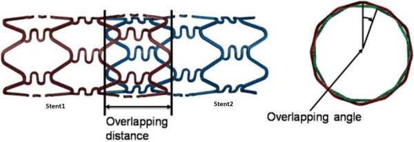
Schematic diagram of overlapping distance and angle. The left stent is referred to as stent 1 and the right one is referred to as stent 2.
As shown in Fig. 1, the overlapping distance was defined as distance between the ends of stent 1 and stent 2 that are in closest proximity, and the overlapping angle was defined as the angle between two adjacent heads of the stents. The overlapping distance was chosen as 3 mm, 3 mm, 1.5 mm, and 3 mm for the four cases studied. The overlapping angle was varied from 0 deg to 30 deg.
Based on overlapping distance, overlapping angle, and balloon types, four different study cases were defined (see Table 1).
Table 1.
Simulation study cases
| Study case | Overlapping distance (mm) | Overlapping angle (deg) | Balloon |
|---|---|---|---|
| Case 1 | 3 | 5 | Semicompliant |
| Case 2 | 3 | 30 | Semicompliant |
| Case 3 | 1.5 | 15 | Semicompliant |
| Case 4 | 3 | 5 | Compliant |
In each of the study cases, stent 1 and stent 2 were both CypherTM-like stents, as shown in Fig. 2. Semicompliant balloons were used in cases 1–3, while fully compliant balloons were used in case 4.
Fig. 2.
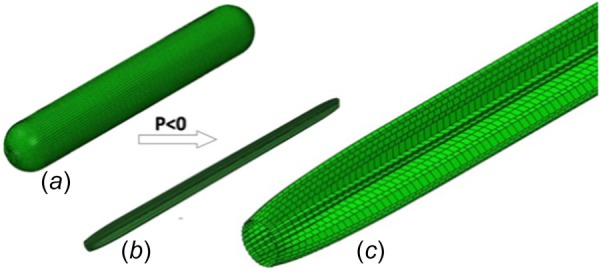
The model of balloon deflation and folding: (a) the unfolded balloon, (b) the folded balloon, and (c) detail of the folded balloon
2.2. Model Geometry and Mesh.
The balloons had a length of 18 mm, diameter of 3 mm, and thickness of 0.05 mm when fully deflated. Two typical clinical balloons were chosen: one is a semicompliant balloon, which was modeled as an isotropic, linear-elastic material with Young's modulus of 900 MPa [16]; the second was a fully compliant balloon which was modeled as an isotropic, linear-elastic material with Young's modulus of 300 MPa [23].Poisson's ratio of 0.30 and density of 2000 kg/m3 were used for both balloons.
The balloons were meshed using four-node membrane elements with reduced integration and hourglass control (abaqus element type M3D4R). The total number of elements for each balloon was 9120, which was based on mesh sensitivity studies [16].
The balloon was initially compressed in an explicit simulation by applying a negative pressure of 0.01 MPa to its inner surface, with proximal and distal ends fully constrained, see Fig. 2. The balloon had a 1.0 mm outer diameter at the end of the deflation process. The deflated balloon was then inserted inside the stent.
The stent used in this study was selected to mimic the CypherTM stent because many researchers reported that CypherTM stents were more commonly observed to fracture in the clinic, especially under overlapping stent conditions [5,10,11]. The stent was a typical closed-cell design with four loops along the axial direction and six struts in each loop. As shown in Fig. 3, the stent length was 6.90 mm, the inner diameter was 1.45 mm, and the strut thickness was 0.1 mm.
Fig. 3.

Stent structure and finite element mesh
The stent was modeled as Co alloy, using an elasto-plastic constitutive model with linear isotropic and kinematic hardening. The material properties of the stent are provided in Table 2.
Table 2.
Material properties of Co alloy
| Young's modulus, | Poisson's ratio, | Yield stress | Tangent modulus, | Density, |
|---|---|---|---|---|
| 250.0 | 0.30 | 840.0 | 2.77 | 8900.0 |
Eight-node linear brick, reduced integration elements with hourglass control (abaqus element type C3D8R), were used to mesh the stent. The total number of elements was 22,701, which was based on mesh sensitivity studies [24]. Images of the stent mesh are provided in Fig. 3.
2.3. Simulation Steps and Boundary Conditions.
The process of modeling stent overlap was divided into five simulation steps, as shown in Fig. 4. The load and simulation time for each step is also provided in Fig. 4. The load steps were as follows:
Fig. 4.
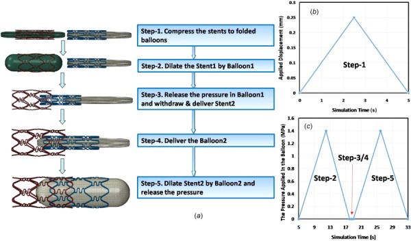
The processes of modeling stent overlap: (a) summarizes the simulation steps, (b) summarizes the displacement applied on the outer surface of the stent in step 1, and (c) is the pressure applied on the inner surface of balloon in steps 2–5
Step 1: Compress stents onto the folded balloons and release the load
This step was a pretreatment step, where each end of the stent was constrained in the circumferential direction and a radial displacement of 0.25 mm was applied on the outer surface to compress each stent onto the balloon. The outer diameter of outer stent was about 1.2 mm after recoil.
Step 2: Dilate stent 1 using balloon 1
In this step, a load of 1.4 MPa, which is within the range of suggested clinical data [18,20], was applied on the inner surface of balloon 1. The two ends of balloon 1 were constrained in all the directions and the two ends of stent 1 were constrained in the circumferential direction. All the degrees-of-freedom for stent 2 and balloon 2 were constrained in this step. The load applied on the inner surface of balloon 1 was gradually released during this step.
Step 3: Withdraw balloon 1 and then deliver stent 2
Balloon 1 was withdrawn from stent 1 after the applied pressure reached zero. The two ends of stent 1 were constrained in the circumferential direction. An axial displacement of 10 mm was applied to balloon 1 so that it could be fully withdrawn from stent 1. One of the overlapping distances listed in Table 1 was applied as an axial displacement for stent 2. As shown in Table 1, the overlapping angle in the four different study cases was applied by rotating stent 2 in the circumferential direction before delivering stent 2. In the simulation process, the two ends of stent 2 were constrained in the circumferential direction and balloon 2 was constrained completely.
Step 4: Deliver balloon 2
All the degrees-of-freedom in the model were constrained in this step, except for the axial displacement of balloon 2. The overlapping distance in the four different study cases was applied as an axial displacement of balloon 2.
Step 5: Inflate balloon 2
The two ends of balloon 2 and stent 1 were constrained in the circumferential direction. The boundary conditions for stent 2 were as described for stent 1 in step 2. Stent 2 was expanded using an applied pressure of 1.4 MPa on balloon 2, the load on balloon 2 was slowly decreased to zero after inflation. Balloon 1 was completely constrained during this step.
In this work, a surface-to-surface contact algorithm was selected to model nonlinear contact in all the steps. A Coulomb friction model was used to model frictional contact between the balloon and stent, as well as the stent and artery. A value of 0.1 was utilized for the entire simulation [19,20].
Due to the highly nonlinear compression/expansion behavior of the balloon and stent, a quasi-static analysis was performed using abaqus/explicit. The simulation time was extended in order to maintain the ratio of kinetic energy to the total strain energy under 5% in each step, resulting in a total simulation time of 33 s. The relationship between simulation time and applied loads is summarized in Fig. 4.
3. Results
Figure 5 shows the deformation of overlapping stents for the four study cases upon completion of all the simulation steps. In each case, the contact patterns of overlapping stents were primarily main strut–main strut, main strut–bridge strut, and bridge strut–bridge strut.
Fig. 5.
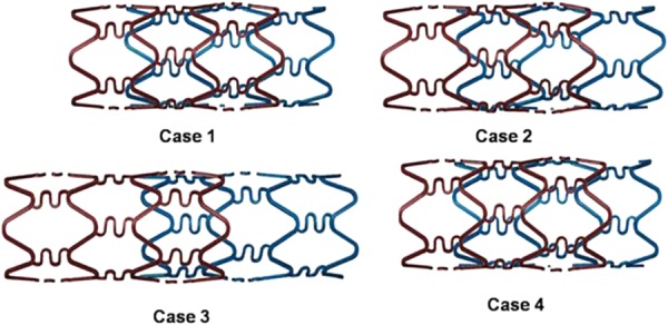
Deformation of overlapping stents upon completion of all the simulation steps
In each case, there were many contact pairs in different positions. Compared with studying contact pairs one by one, it was more effective and convenient to compare the contact patterns, overlapping stents interaction mechanism, and contact pressure distribution in different study cases.
Three contact patterns between the overlapping stents were observed in all the cases: edge-to-surface, edge-to-edge, and no contact. The details of each contact pattern and the differences between them are described as follows.
The edge-to-edge contact pattern mainly occurred between two strut edges, with the contact pressure concentrated on the edges of every stent, as shown in Fig. 6.
Fig. 6.
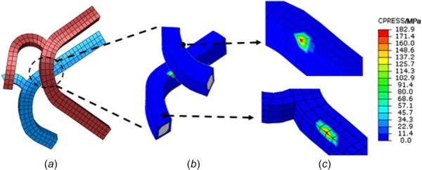
Edge-to-edge contact pattern of overlapping stents. Contact pressure results shown in (b) and (c). A concentration of pressure is predicted on both edges of the contact pairs.
The edge-to-surface contact pattern occurred between the strut surface of one stent and the edge of the other. Peak contact pressure only appeared on the stent edge, and no contact pressure concentration was observed on the strut surface, as shown in Fig. 7.
Fig. 7.
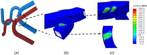
Edge-to-surface contact pattern of overlapping stents. Contact pressure is shown in (b) and (c). Pressure concentrations were predicted on one edge of the contact pairs.
Figure 8 shows an example of overlapping stents with no contact. As shown in Figs. 8(b) and 8(c), there was a significant gap between the two stents in this contact pattern, and the contact pressure was zero.
Fig. 8.

Overlapping stents with no contact pattern
Table 3 summarizes results for the peak contact pressure in all the four cases after all the loads were released. It shows that the peak contact pressure usually occurred in the edge-to-surface contact pattern on the edge of stent 1.
Table 3.
Maximum contact pressure in the four study cases
|
Max contact pressure |
|||
|---|---|---|---|
| Value (MPa) | Contact pattern | Position | |
| Case 1 | 552.3 | Edge-to-surface | Edge of stent 1 |
| Case 2 | 479.0 | Edge-to-edge | Edge of stent 1 |
| Case 3 | 438.1 | Edge-to-surface | Edge of stent 1 |
| Case 4 | 565.3 | Edge-to-surface | Edge of stent 1 |
Although the analysis of peak contact pressure was useful to analyze stent-to-stent interactions, the analysis of stent interactions in other parts was still needed to provide a comprehensive understanding of overlapping stent interactions.
Figure 9 summarizes the frequency of different contact patterns under different contact pressure ranges with a load of 1.4 MPa applied on balloon 2. It was seen that a contact pressure greater than 500 MPa only occurred in cases 1 and 4, with an occurrence of three and four times, respectively. The number of contacts in the contact pressure range of 400–500 MPa was 3, 6, 1, and 7 for cases 1, 2, 3, and 4, respectively. In the contact pressure range of 300–400 MPa, the number of contacts was 11, 8, 8, and 7 for the four cases, respectively. The number of contacts was 12, 8, 13, and 8 for cases 1, 2, 3, and 4, respectively, in the range from 200 to 300 MPa.
Fig. 9.
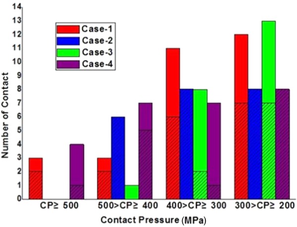
Statistics of stent contact number for different contact pressure ranges. The shaded zone represents the number of edge-to-edge contacts and the solid zone represents the number of edge-to-surface contacts.
4. Discussion
4.1. Why There Is No Surface-to-Surface Contact Pattern?
No surface-to-surface contact is observed in all the cases. This phenomenon is possibly caused by the following factors.
The first factor relies on the tubelike structure of stents. The stent struts are distributed in a cylindrical surface instead of a flat plane due to its tubelike geometry, as shown in Figs. 10(a) and 10(b). During the stent overlapping process, stent 1 has been dilated completely before stent 2 is placed inside. The outer surface of stent 2 interacts with the inner surface of stent 1 as shown in Figs. 10(b), 10(c), and 10(d). In this situation, the contact first appears in the edges of struts as shown in Figs. 10(c) and 10(d). Even considering the polishing of stents in clinical practice, the strut section still appears as a fan-shape as shown in Fig. 10(e).
Fig. 10.
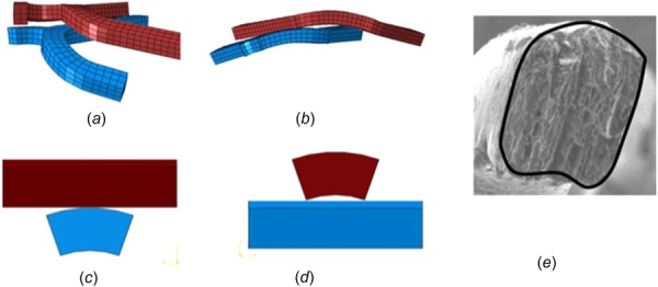
Schematic diagram of tubelike structure of stents. (a) and (b) A portion of overlapping stents, the red stent is stent 1 and the blue stent is stent 2, (c) and (d) schematic diagram of the interaction of stent struts whose section is not rectangular but fan-shaped, and (e) SEM picture of an actual stent strut cross section.
Second, the nonuniform deformation of stents also leads to no surface-to-surface contact in the stent overlap process. The stent struts appeared as a nonconcentric cylindrical surface in the axial direction after complete dilation because of the nonuniform deformation. As shown in Fig. 10(a), the struts of two stents have been warped and intertwined together, making the heads and ends of the stent no longer a cylinder surface in the axial direction.
One of the reasons for the warped struts was the “dog bone” effect during stent expansion. Figures 11(a) and 11(b) illustrate the typical “dog bone” effect during stent expansion. The main reason for the “dog bone” effect is that the dilation of the balloon at both stent ends is higher than in the central region, leading to greater stent deformation at the ends. This phenomenon also appears in other parts of the stent, which we refer to as the “local dog bone” effect, as shown in Figs. 11(c) and 11(d). The source of the “local dog bone” effect is similar to the “dog bone” effect: the balloon has extruded through the stent gaps and warps the stent locally, as shown in Figs. 11(c) and 11(d).
Fig. 11.
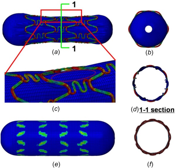
Diagrams of the “dog bone” effect and “local dog bone” effect. (a) The “dog bone” effect during stent expansion, (b) the “dog bone” effect as viewed along the axial direction, (c) the “local dog bone” effect during stent expansion, (d) the “local dog bone” effect from 1 to 1 section view, (e) the contact pressure distribution after the load has been released, and (f) the nonuniform deformation of the overlapping stent as viewed from the axial direction.
Figure 11(e) shows the pressure distribution in the balloon. It demonstrates that the ends of the struts do not contact the balloon directly and that they have been warped. When viewed along the axial direction, the strut ends have warped and the struts of two stents are no longer cylindrical surfaces, as shown in Figs. 11(e) and 11(f).
Thus, during stent expansion, the ends of the struts are warped. As a result, the deformed stent strut is no longer in a cylindrical configuration. As shown in Fig. 11(a), 11(c), and 11(d), there is nonplanar contact between the two warped struts, thus surface-to-surface contact seldom appears in this condition. The stent interaction often occurs in the shape of the contact patterns as shown in Figs. 6–8.
4.2. How Is the Edge to Edge/Surface Contact Formed During Overlapping Process?
Figure 12 summarizes the statistics for number of stent contacts under different loads applied on balloon 2. When the load applied on balloon 2 is 0.5 MPa, most of the contact patterns were edge-to-edge contact, with only one edge-to-surface contact occurring in case 2. With the load increasing, the contact number of overlapping stents increases. When the load applied on balloon 2 is 0.7 MPa, the number of edge-to-surface contacts was predicted to be more than that when the load is 0.5 MPa, the percent of edge-to-edge contact to all the contact numbers decreased in cases 1–4. When the load was 1.0 MPa, the number of contacts increased in all the four study cases, but the percentage of edge-to-edge contacts decreased. When the load applied on balloon 2 was 1.4 MPa, the contact number of overlapping stents reached the maximum value. All the contacts were edge-to-edge contact in case 2. In cases 1, 2, and 4, the increment rate of contact number of edge-to-edge contact pattern was less than the increment rate of all the contact of overlapping stents.
Fig. 12.
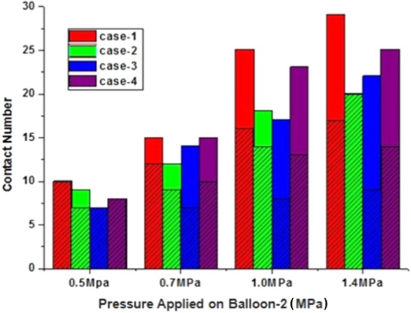
The statistics of stent contact number at different load ranges applied on balloon 2. The shaded zone represents the number of edge-to-edge contacts and the solid zone represents the number of edge-to-surface contacts.
Our research suggests that during the overlapping process of two stents, some edge-to surface contact changed into edge-to-edge contact (when the load was small the contact pattern was edge-to-surface, with the load increasing, it changed into edge-to-edge contact, such as in case 3), and some edge-to-edge contact changed into edge-to-surface contact with increasing load. One of the processes of edge-to-surface contact changing into edge-to-edge contact is shown in Fig. 13, and Fig. 14 shows the one of the processes of edge-to-edge contact changing into edge-to-surface contact.
Fig. 13.

The evolution of edge-to-surface contact changing into edge-to-edge contact during implantation of an overlapping stent
Fig. 14.
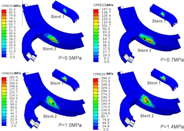
The evolution of edge-to-edge contact changing into edge-to-surface contact during implantation of the overlapping stent
Figure 13 shows the evolution of contact pressure during overlapping after edge-to-edge contact appears. The contact pattern is edge-to-surface when the load applied on balloon 2 was 0.5 MPa and the maximal contact pressure of 127.0 MPa occurred in the surface of stent 1. With the load increasing, if the load applied in balloon 2 was 0.7 MPa, the maximal contact pressure of 196.1 MPa occurred in the edge of stent 1. Thus, the maximal contact pressure zone had moved from the surface to the edge. The contact pattern changed from edge-to-surface to edge-to-edge. With the load increasing up to 1 MPa, the maximal contact pressure was 292.2 MPa, the maximal contact pressure zone moved along the edge of stent 1. With the load increasing up to 1.4 MPa, the maximal contact pressure was 352.7 MPa and the maximal contact pressure zone in the edge of stent 1 was expanded. The increased contact pressure indicates a larger level of extrusion between the two stents, and the maximal extrusion zone between the two stents is migrating as the load increases. The phenomenon of migration of the extrusion zone suggests the presence of slip between overlapping stents.
Figure 14 shows the evolution of contact pressure during overlap after edge-to-surface contact appears. The contact pattern is edge-to-edge if the dilating pressure remains in the range of 0.5–0.7 MPa. The peak contact pressure in the range of 91.2–147.9 MPa mainly occurred in the edge of stent 2. The peak contact pressure zone in the edge of stent 2 expanded along the edge with the load increased from 0.5 MPa to 0.7 MPa. With the load increasing, the peak contact pressure first occurred in the surface of stent 2 and then edge-to-surface contact appeared, eventually forming in the edge of stent 1 and surface of stent 2. When load was 1.0 MPa, the maximal contact pressure was 182.9 MPa, occurring in the edge of stent 1, and the peak contact pressure of stent 2 was approximately 140 MPa. This suggests that in the overlapping stent, the contact pressure was more concentrated in the edge of stent. At the same time, the contact zone (as marked by the arrow) also is migrating with the increasing load.
In the overlapping process of two stents, the contacts appeared among parts of two stents with the pressure increasing. At the lower load level, most of the contacts were edge-to-edge (as shown in Fig. 12 when the load was 0.5 MPa only one edge-to-surface contact occurred in case 2). Because stent 1 has been dilated with warped struts during the expansion of stent 2, the edge-to-edge contact readily occurs. As the expansion pressure increases, some of stent 2's struts slip along the edges of stent 1. Gradually, some edge-to-edge contacts transform into edge-to-surface contacts. Edge-to-surface contact appears when the applied load is large enough. This is also why most peak contact pressure occurs in the edge-to-surface contact pattern in different study cases, as shown in Table 3.
4.3. Stent Safety.
From a clinical point of view, the edge-to-edge contact pattern is more dangerous than the edge-to-surface contact pattern because the stents have a trend of cutting each other during flow pulsation, which is not ideal for stent integrity because the contact pressure is concentrated on the edges. The stent contact pattern and contact pressure distribution may have a close relation with SF. From the simulation results, it is suggested that SF may be more common along stent edges because the strut edge is sharp and the contact pressure is more concentrated.
The predicted results regarding fracture position of overlapping stents are compared favorably with those reported in the literature [25]. In this study, an experiment of overlapping stents under different bending curvatures was carried out to test overlapping stent safety.
As shown in Figs. 6, 7, 13, and 14, whether in the edge-to-edge contact pattern or in the edge-to-surface contact pattern, there is a trend of the struts to cut each other. Shear sliding between the struts becomes severe and could eventually lead to fracture because of the effect of edge-to-edge shear and the long-term exposure to pulsating blood pressure.
In the future, extending the current work to analyze overlapping stents under dynamic conditions such as pulsating flow or dynamic loading can further our understanding on SF mechanisms of overlapping stents.
5. Conclusions
In this work, the interaction between two overlapping stents was studied. We mainly studied the interaction types, location, and how the interaction between overlapping stents occurs. It was found that all the overlapping contact patterns between struts are edge-to-edge or edge-to-surface. No surface-to-surface contact pattern was predicted by the model. This phenomenon is mainly caused by the nonuniform deformation of stents in the radial direction and the stent's tubular structure during implantation of the overlapping stent. After expansion of the second stent, the contact pressure is primarily concentrated on the edges of the stents, which suggests that the failure of an overlapping stent frequently occurs along stent edges. This study helps better understand the nature of stent overlap and conditions for future research when testing overlapping stents.
6. Limitations
This work is a preliminary study on overlapping stents. The main aim was to investigate the interaction between two overlapping stents. Many factors such as the stent type, other overlapping modes, the artery, stress analysis, fatigue analysis of overlapping stents, the recoil of the stent after ballooning, and other factors were not included. Fatigue analysis is a particular concern since it is closely related to stent fracture. Here, we predicted SF in overlapping stents as related to their contact interaction. It is just a conjecture at this time, and further research about stent fracture and the mechanical properties of overlapping stents is needed.
Acknowledgment
This work was supported by a grant from National High-Tech Program of China (Grant No. 2006AA02A139), NSFC (Grant Nos. 11372257 and 1330031) for J. Y., National Science Foundation Grant No. CBET-1516236, and National Institute of Health Grant No. R01HL131750 for Y. L. and doctorial innovation fund of SWJTU for J. Xu. Our deepest gratitude goes to the anonymous reviewers for thoughtful suggestions that have helped improve this paper.
Contributor Information
Jiang Xu, School of Mechanics and Engineering, , Southwest Jiaotong University, , Chengdu 610031, China , e-mail: xujiang0123@163.com.
Jie Yang, School of Mechanics and Engineering, , Southwest Jiaotong University, , Chengdu 610031, China , e-mail: yangchenjie@home.swjtu.edu.cn.
Salman Sohrabi, Department of Mechanical , Engineering and Mechanics, , Lehigh University, , Bethlehem, PA 18015 , e-mail: sas713@lehigh.edu.
Yihua Zhou, Department of Mechanical , Engineering and Mechanics, , Lehigh University, , Bethlehem, PA 18015 , e-mail: yiz311@lehigh.edu.
Yaling Liu, Bioengineering Program, , Lehigh University, , Bethlehem, PA 18015;; Department of Mechanical , Engineering and Mechanics, , Lehigh University, , Bethlehem, PA 18015 , e-mail: yal310@lehigh.edu
References
- [1]. Chen, C.-W. , and Lin, C.-L. , 2009, “ The Current Status of Coronary Drug-Eluting Stents,” Tzu Chi Med. J., 21(1), pp. 18–27. 10.1016/S1016-3190(09)60004-5 [DOI] [Google Scholar]
- [2]. Hara, H. , Nakamura, M. , Palmaz, J. C. , and Schwartz, R. S. , 2006, “ Role of Stent Design and Coatings on Restenosis and Thrombosis,” Adv. Drug Delivery Rev., 58(3), pp. 377–386. 10.1016/j.addr.2006.01.022 [DOI] [PubMed] [Google Scholar]
- [3]. Chinikar, M. , and Sadeghipour, P. , 2014, “ Coronary Stent Fracture: A Recently Appreciated Phenomenon With Clinical Relevance,” Curr. Cardiol. Rev., 10(4), pp. 349–354. 10.2174/1573403X10666140404105923 [DOI] [PMC free article] [PubMed] [Google Scholar]
- [4]. Yamada, K. P. , Koizumi, T. , Yamaguchi, H., Kaneda, H., Bonneau, H. N., Honda, Y., and Fitzgerald, P. J., 2008, “ Serial Angiographic and Intravascular Ultrasound Analysis of Late Stent Strut Fracture of Sirolimus-Eluting Stents in Native Coronary Arteries,” Int. J. Cardiol., 130(2), pp. 255–259. 10.1016/j.ijcard.2007.08.082 [DOI] [PubMed] [Google Scholar]
- [5]. Ruchin, P. E. , Trabattoni, D. , Fabbiocchi, F. , Montorsi, P. , Lualdi, A. , Ravagnani, P. , Grancini, L. , Galli, S. , Teruzzi, G. , and Calligaris, G. , 2009, “ Use of Multiple Overlapping Sirolimus-Eluting Stents for Treatment of Long Coronary Artery Lesions: Results From a Single-Center Registry in 318 Consecutive Patients,” Int. J. Cardiol., 134(2), pp. 231–237. 10.1016/j.ijcard.2008.02.012 [DOI] [PubMed] [Google Scholar]
- [6]. Räber, L. , Jüni, P. , Löffel, L. , Wandel, S. , Cook, S. , Wenaweser, P. , Togni, M. , Vogel, R. , Seiler, C. , and Eberli, F. , 2010, “ Impact of Stent Overlap on Angiographic and Long-Term Clinical Outcome in Patients Undergoing Drug-Eluting Stent Implantation,” J. Am. Coll. Cardiol., 55(12), pp. 1178–1188. 10.1016/j.jacc.2009.11.052 [DOI] [PubMed] [Google Scholar]
- [7]. Kang, W. C. , Ahn, T. H. , and Ek, S. , 2007, “ Multiple Stent Strut Fracture-Induced Restenosis in a Diffuse Long Lesion Treated With Overlapping Heterogeneous Drug-Eluting Stent,” Int. J. Cardiol., 130(1), pp. e30–e33. 10.1016/j.ijcard.2007.07.032 [DOI] [PubMed] [Google Scholar]
- [8]. Nakazawa, G. , Finn, A. V. , Vorpahl, M. , Ladich, E. , Kutys, R. , Balazs, I. , Kolodgie, F. D. , and Virmani, R. , 2009, “ Incidence and Predictors of Drug-Eluting Stent Fracture in Human Coronary Artery: A Pathologic Analysis,” J. Am. Coll. Cardiol., 54(21), pp. 1924–1931. 10.1016/j.jacc.2009.05.075 [DOI] [PubMed] [Google Scholar]
- [9]. Costa, J. D. R. , and Mintz, G. S. , 2005, “ Intravascular Ultrasonic Assessment of Stent Diameters Derived From Manufacturer's Compliance Charts,” Am. J. Cardiol., 96(1), pp. 74–78. 10.1016/j.amjcard.2005.02.049 [DOI] [PubMed] [Google Scholar]
- [10]. Ian Buysschaert, M. D. , Elias Sanidas, M. D. , Takao Hasegawa, M. D. , Bon-Kwon Koo, M. D. , Yasuhiro Honda, M. D. , Fitzgerald, P. J. , and Stefan Verheye, M. D. , 2014, “ Baseline and 9 Months IVUS Analysis of the Bifurcation-Dedicated Biolimus A9-Eluting Axxess Stent System: The DIVERGE IVUS Substudy,” Catheterization Cardiovasc. Interventions, 84(7), pp. 1062–1070. 10.1002/ccd.25414 [DOI] [PubMed] [Google Scholar]
- [11]. Takamiya, Y. , Miura, S. I., Tsuchiya, Y., Fukuda, Y., Zhang, B., Kuwano, T., Ike, A., Yanagi, D., Kubota, K., Mori, K., Iwata, A., Nishikawa, H., Kawamura, A., Miller, N., Matsuo, K., Shirai, K., and Saku, K., 2011, “ Angiographic late lumen loss at the site of overlap of multiple Cypher™ sirolimus-eluting stents: ALSOCE study,” J. Cardiol., 57(2), pp. 187–193. 10.1016/j.jjcc.2010.11.005 [DOI] [PubMed] [Google Scholar]
- [12]. Hecht, H. S. , Polena, S. , Jelnin, V. , Jimenez, M. , Bhatti, T. , Parikh, M. , Panagopoulos, G. , and Roubin, G. , 2009, “ Stent Gap by 64-Detector Computed Tomographic Angiography: Relationship to In-Stent Restenosis, Fracture, and Overlap Failure,” J. Am. Coll. Cardiol., 54(21), pp. 1949–1959. 10.1016/j.jacc.2009.06.045 [DOI] [PubMed] [Google Scholar]
- [13]. Chung, M. S. , Yang, D. H. , Kim, Y. H. , Roh, J. H. , Song, J. , Kang, J. W. , Ahn, J. M. , Park, D. W. , Kang, S. J. , Lee, S. W. , Park, S. W., Park, S. J., and Lim, T. H., 2015, “ Stent Fracture and Longitudinal Compression Detected on Coronary CT Angiography in the First- and New-Generation Drug-Eluting Stents,” Int. J. Cardiovasc. Imaging, 32(4), pp. 1–10. 10.1007/s10554-015-0798-4 [DOI] [PubMed] [Google Scholar]
- [14]. Holzapfel, G. A. , and Gasser, T. C. , 2007, “ Computational Stress-Deformation Analysis of Arterial Walls Including High-Pressure Response,” Int. J. Cardiol., 116(1), pp. 78–85. 10.1016/j.ijcard.2006.03.033 [DOI] [PubMed] [Google Scholar]
- [15]. De Beule, M. , Mortier, P. , Carlier, S. G. , Verhegghe, B. , Van Impe, R. , and Verdonck, P. , 2008, “ Realistic Finite Element-Based Stent Design: The Impact of Balloon Folding,” J. Biomech., 41(2), pp. 383–389. 10.1016/j.jbiomech.2007.08.014 [DOI] [PubMed] [Google Scholar]
- [16]. Xu, J. , Yang, J. , Huang, N. , Uhl, C. , Zhou, Y. , and Liu, Y. , 2016, “ Mechanical Response of Cardiovascular Stents Under Vascular Dynamic Bending,” Biomed. Eng. Online, 15(1), pp. 1–20. 10.1186/s12938-016-0135-8 [DOI] [PMC free article] [PubMed] [Google Scholar]
- [17]. Yang, J. , Liang, M. B. , Huang, N. , Liu, Y. L. , and Shah, S. , 2010, “ Studying the Non-Uniform Expansion of a Stent Influenced by the Balloon,” J. Med. Eng. Technol., 34(5–6), pp. 301–305. 10.3109/03091902.2010.481031 [DOI] [PubMed] [Google Scholar]
- [18]. Perrin, D. , Badel, P. , Orgéas, L. , Geindreau, C. , Dumenil, A. , Albertini, J.-N. , and Avril, S. , 2015, “ Patient-Specific Numerical Simulation of Stent-Graft Deployment: Validation on Three Clinical Cases,” J. Biomech., 48(10), pp. 1868–1875. 10.1016/j.jbiomech.2015.04.031 [DOI] [PubMed] [Google Scholar]
- [19]. Debusschere, N. , Segers, P. , Dubruel, P. , Verhegghe, B. , and De Beule, M. , 2015, “ A Finite Element Strategy to Investigate the Free Expansion Behaviour of a Biodegradable Polymeric Stent,” J. Biomech., 48(10), pp. 2012–2018. 10.1016/j.jbiomech.2015.03.024 [DOI] [PubMed] [Google Scholar]
- [20]. Hsiao, H.-M. , Chiu, Y.-H. , Lee, K.-H. , and Lin, C.-H. , 2012, “ Computational Modeling of Effects of Intravascular Stent Design on Key Mechanical and Hemodynamic Behavior,” Comput. Aided Des., 44(8), pp. 757–765. 10.1016/j.cad.2012.03.009 [DOI] [Google Scholar]
- [21]. Zhang, P. , Sun, A. , Zhan, F. , Luan, J. , and Deng, X. , 2014, “ Hemodynamic Study of Overlapping Bare-Metal Stents Intervention to Aortic Aneurysm,” J. Biomech., 47(14), pp. 3524–3530. 10.1016/j.jbiomech.2014.08.025 [DOI] [PubMed] [Google Scholar]
- [22]. Rikhtegar, F. , Wyss, C. , Stok, K. S. , Poulikakos, D. , Müller, R. , and Kurtcuoglu, V. , 2014, “ Hemodynamics in Coronary Arteries With Overlapping Stents,” J. Biomech., 47(2), pp. 505–511. 10.1016/j.jbiomech.2013.10.048 [DOI] [PubMed] [Google Scholar]
- [23]. Yang, J. , Huang, N. , and Du, Q. X. , 2009, “ A Non-Uniform Expansion Mechanical Safety Model of the Stent,” J. Med. Eng. Technol., 33(2), pp. 525–531. 10.1080/07434610902744082 [DOI] [PubMed] [Google Scholar]
- [24]. Morlacchi, S. , Pennati, G. , Petrini, L. , Dubini, G. , and Migliavacca, F. , 2014, “ Influence of Plaque Calcifications on Coronary Stent Fracture: A Numerical Fatigue Life Analysis Including Cardiac Wall Movement,” J. Biomech., 47(4), pp. 899–907. 10.1016/j.jbiomech.2014.01.007 [DOI] [PubMed] [Google Scholar]
- [25]. Kapnisis, K. K. , Halwani, D. O. , Brott, B. C. , Anderson, P. G. , Lemons, J. E. , and Anayiotos, A. S. , 2013, “ Stent Overlapping and Geometric Curvature Influence the Structural Integrity and Surface Characteristics of Coronary Nitinol Stents,” J. Mech. Behav. Biomed. Mater., 20, pp. 227–236. 10.1016/j.jmbbm.2012.11.006 [DOI] [PubMed] [Google Scholar]


