Abstract
Frustration is a powerful mechanism in condensed matter systems, driving both order and complexity. In smectics, the frustration between macroscopic chirality and equally spaced layers generates textures characterized by a proliferation of defects. In this article, we study several different ground states of the chiral Landau–de Gennes free energy for a smectic liquid crystal. The standard theory finds the twist grain boundary (TGB) phase to be the ground state for chiral type II smectics. However, for very highly chiral systems, the hierarchical helical nanofilament phase can form and is stable over the TGB.
Keywords: smectic liquid crystals, twist grain boundary phase, helical nanofilament phase, screw dislocations
1. Introduction
Chirality is a ubiquitous driver of form and complexity in a host of systems—from biologic to chemical to physical. Competition between local chiral order and the geometric constraints of packing yield a proliferation of complex and hierarchical geometric phases [1–4]. The physical system can respond to this type of frustration in any number of ways. It can suppress either source of competition and behave as the bulk phase in the absence of it. This typically occurs in regimes where the energetic cost associated with the source frustration is small. However, when the terms are comparable, the system has to find a compromise. One way it can do this is by admitting chirality in small regions of the frustrated phase via the introduction of topological defects—points, lines or walls where the symmetry of the phase changes.
Topological defects often characterize a particular phase of a condensed matter system as they are defined by the interface between regions with different symmetries. Although typically the hallmark of a phase transition, topological defects can also arise from frustration within a system. They act to mediate the frustration induced by two competing yet mutually exclusive terms in the free energy. The Abrikosov phase of type II superconductors might be the most familiar example of this. A lattice of flux vortices reconciles the Meissner effect of the superconducting state with an applied magnetic field. Such frustration exists in soft matter systems and frequently results in complex geometrical states of matter. The prototypical example is the chiral smectic-A*, a phase of liquid crystals that favours equally spaced layers and inherent molecular chirality. These two conditions cannot be simultaneously satisfied, resulting in frustration.
Frustration need not be an intrinsic property of the free energy functional. In geometric frustration, the symmetries of the local groundstate or microstructure are not a subset of the symmetries of the manifold on which the system lives. In the smectic-A* phase, molecular chirality is incompatible with equally spaced layers. A proliferation of phases attempts to mediate between these two extremes. Most notably, the twist grain boundary phase (TGB) employs grain boundaries created from an infinite row of parallel screw dislocations to rotate flat layers [5].
The helical nanofilament (HN) phase, like the TGB phase, originates from the intrinsic frustration between the equally spaced layered smectic phase and macroscopic chirality. In systems of achiral bent-core liquid crystals and mixtures of achiral bent-core and rod-like molecules, chiral phases often arise from spontaneous symmetry breaking [6–9]. Macroscopic homochiral domains populate the sample, with both handednesses occurring with equal probability. Unlike the B2 and B3 bent-core phases, where molecular tilt with respect to the smectic layers admits chirality through the spontaneous breaking of mirror symmetry, the HN phase, a smectic-A phase, allows the director to twist with respect to the layers [10–13].
Although initially considered to have the same morphology as the TGB, the hierarchical structure of the HN phase exhibits a distinctively different motif. Upon cooling from a high-temperature fluid phase, helical bundles consisting of approximately five nested smectic layers, nucleate. These homochiral, coherently rotating filaments form the basis of the hierarchical HN phase. They assemble, with axes aligned, into a hexagonal lattice producing a nanoporous bulk structure. From freeze fracture experiments on the bulk HN texture, an archetypal Bouligand texture [1,14] reveals an underlying cholesteric texture with the pitch direction parallel to the centre of the filaments [15]. The HN phase accommodates chirality by forming helicoidal layers that locally match a cholesteric texture at the expense of long ranged ordering of the layers. Conversely, the TGB phase locally prefers flat layers, only admitting chirality across grain boundaries, thus allowing the layer normal to rotate by a fixed angle.
This article is organized as follows. In §2, we discuss the Landau–de Gennes model for the smectic free energy. Sections 3 and 4 concern, respectively, the TGB phase and the HN phase including both the mathematical description of their morphologic structure and the free energy for their formation. In §5, we present a unified phase diagram for four chiral liquid cryastalline phases: the cholesteric, the smectic-A, the TGB and the HN phase.
2. The smectic free energy
Landau–de Gennes theory has proven exceedingly powerful in understanding the phase behaviour of smectics, particularly the nematic to smectic-A transition (NA) [16]. The onset of smectic order is characterized by the development of a mass density wave locally modulating the molecular positions. In mean-field theory, a non-zero value for the complex smectic-order parameter ψ(x) = ψ0(x) eiqsmϕ(x) indicates both the emergence of smectic order and the location of smectic layers denoted by level sets of the phase field ϕ = nd, where d = 2π/qsm is the layer spacing. Gauge-like minimal coupling of the nematic director field n to the smectic-order parameter, reminiscent of the Landau–Ginzburg theory for superconductors, penalizes deviations of the director field from the layer normal N. The low energy deformations to the nematic director field still cost energy in the smectic phase. This phenomenology is captured by the Landau–de Gennes free energy
 |
2.1 |
where q0 is the chirality of the high-temperature cholesteric phase and the three terms of the Frank free energy describe the splay, twist and bend deformations of the nematic field. Further discussion shall be restricted to the London limit [17] (unless otherwise specified), where gradients in the magnitude of the smectic order may be neglected.
The ratio of two natural lengthscales, κG = λ/ξ, the twist Ginzburg parameter, governs the phase behaviour of chiral smectics: the twist penetration depth is the maximum length the director can deviate from the layer normal, λ = (K2/B)1/2, where B = 2Cq2smψ20 is the compression modulus and the coherence length ξ = (C/|t − tc|)1/2 is the distance over which ψ0 decays to zero. Type I materials  completely expel chirality from the smectic phase. In the smectic phase ψ0 ≠ 0, the free energy density attains its minimal value
  corresponding to the order parameter
  , and the cholesteric phase becomes favourable above the thermodynamic critical chirality qth =
  .
.
In the case of a mixed phase, containing both smectic and cholesteric qualities, a simple treatment no longer governs the thermodynamic properties. Deformations of the director field and layer spacing simultaneously contribute to the nature of the phase. Restricting to regions within the smectic phase, the free energy reduces to
 |
2.2 |
3. The twist grain boundary phase
The TGB phase, an intermediate phase featured in type II materials ( ) admits chirality into the smectic via grain boundaries formed from an infinite row of parallel screw dislocations. Each grain boundary joins two regions of smectic-A together by rotating the layer normals through an angle α = 2tan−1(a/ℓd), which depends on the separation between defects ℓd. A lattice of parallel grain boundaries separated by ℓb enable the smectic normals to approximately follow an underlying cholesteric texture with the average chirality
3.1. The morphology of the twist grain boundary phase
Before calculating the free energy density of the TGB phase, the natures of both the layer morphology and director field need be made manifest. The Euler–Lagrange equation for the free energy functional, equation (2.2), in the one elastic constant approximation (K1 = K2 = K3 = K), given by
| 3.1 |
| 3.2 |
can be difficult to solve for generic director field n. If the director field is divergence free, the phase field will always be given by harmonic functions. For instance, the phase field for a single screw dislocation,  , satisfies Laplace's equation everywhere except along the lower dimensional set y = 0, x = 0 which defines the dislocation core.
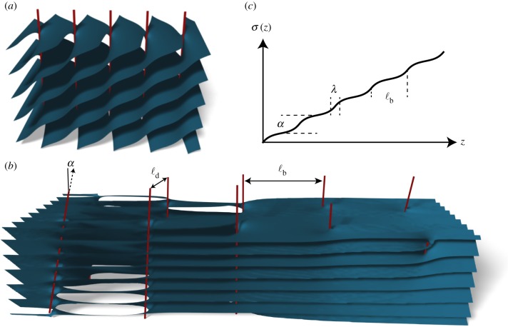
In the low chirality limit, only a single grain boundary need be considered [5], which is given by Scherk's first surface (shown in figure 1a) [18]. The π/2 TGB has the morphology of Schnerk's first surface [19,20]. We shall begin with the phase field for a single grain boundary
 |
3.3 |
that rotates layers at z =−∞, ϕ−= x cos(α/2) − y sin(α/2) by α to ϕ+= x cos(α/2) + y sin(α/2) at z =+∞, where 2 sin(α/2) = b/ℓd, −b is the winding of the phase around any of the line singularities, and ℓd is the spacing between defects within the grain boundary. A branch point singularity marks each of the screw dislocations in the grain boundary at z = 0 and 
Figure 1.
(a) A single grain boundary consists of an infinite row of helicoidal dislocations along the x-axis, separated by spacing ℓd. This rotates planar layers at z =−∞ through an angle α at z =+∞. (b) The bulk TGB phase results from combining an infinite row of these grain boundaries periodically along the z-axis, separated by ℓb. Each grain boundary rotates the layer normals through angle α, thus the grain boundaries themselves must be rotated with respect to one another along the z-axis. (c) The director field n = cos(σ(z))ex + sin(σ(z))ey also rotates in accordance with the layers. It is close to constant within each grain and jumps through angle α across each grain boundary. The width of this jump is given by the penetration depth λ.
A TGB bulk phase consists of a periodic array of grain boundaries living in the plane perpendicular to the pitch direction  , each rotated by α about
  with respect to the previous grain boundary. The corresponding set of singularities exist at
  The natural extension of the phase field becomes
 |
3.4 |
where ϕ±∞ are the asymptotic values of the phase field as  . In place of specifying the asymptotic values ϕ± ∞ of the phase field, it often proves more convenient to specify the behaviour at the origin, for instance, taking that there is a grain boundary at z = 0, with the axes of the screw dislocations parallel to the x-axis. If we note that the asymptotic values may be written as
  , where
  , then the phase field for the bulk TGB with specified behaviour at the origin is given by
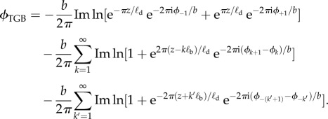 |
3.5 |
The morphology of this structure is shown in figure 1b. This form of the phase field has the advantage as it highlights the exponential overlap between grain boundaries.
3.2. The energetics
To simplify the following calculations, the compression term in the free energy may be split into two terms, |∇ϕ − n|2 = (|∇ϕ|2 − 1) + 2(1 − n · ∇ϕ), where the first term enforces equal spacing of layers and the second may be viewed as an effective potential felt by the director field. The gradient of the phase field will be necessary for calculating the director field and the free energy, which, upon some manipulations, is given by
| 3.6 |
where
 |
3.7 |
First we compute the layer compression energy density
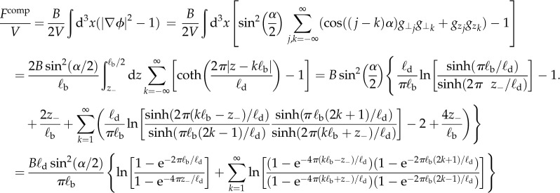 |
3.8 |
where the cut-off z−∼ξ is the size of the dislocation cores.
A full treatment of this problem would employ a completely general director field n = cos(τ(r))(cos(σ(r))ex + sin(σ(r))ey) + sin(τ(r))ez, where σ(r) and τ(r) and generic rotations of the director field about the z- and x-axes, respectively. However, we shall consider an effective model for the director field, n = cos(σ(z))ex + sin(σ(z))ey, as n · ∇ϕ becomes integrable. The resulting effective free energy for the director field is given by1
| 3.9 |
where  is the piecewise constant grain angle of the mth grain. As each of the grains are identical, after a shift and rotation, it is sufficient to consider σ0 = σ − α0 in the region 0 ≤ z ≤ ℓb, with boundary conditions σ0(ℓb/2) = 0 and σ0(0) =−α/2. The solution to this variant of the sine-Gordon equation is given by the elliptic amplitude function
| 3.10 |
where the value of the elliptic modulus m is set by the implicit equation  shown in figure 1c. Free energy density for the director field is
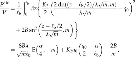 |
3.11 |
where the elliptic functions are defined as dn2(z, m) = 1 − m sn2(z, m) with sn(z, m) = sin(am(z, m)) and 
 is the incomplete elliptic integral of the second kind.
The transition between smectic-A and TGB occurs at  when the energy gain from introducing twist outweighs the cost of introducing a single defect. Calculating the boundary between the TGB and cholesteric phases requires an examination of the stability operator M(x, x′) =
  = 2C{−∇2− ξ−2+ q2sm|∇ϕ − n|2}δ(x−x′). In the linear approximation, ϕ = ϕ±j within each grain, the eigenfunctions are those of a harmonic oscillator and the minimal eigenvalue is qsmq0 − ξ−2. Thus, the onset of order coincides with the first eigenvalue of the stability operator going negative at
  . [5]
. [5]
4. The high chirality limit and the helical nanofilament phase
Conversely, the HN phase requires a high background chirality in order to form. Thus, we consider quenching smectic layers from a background pure cholesteric phase given by n = cos(q0z)ex + sin(q0z)ey. Growing layers from this configuration tries to minimize the compression term of the free energy  . If the cholesteric director field is confined to the xy-plane, rotation in registry along the pitch direction will minimize compression along the z-axis. Under this assumption, the constrained Euler–Lagrange equation for this system is given by
| 4.1 |
Being a pure twist configuration implies ∇ × n =−q0n, which violates the integrability condition for a scalar field ∇ϕ = n. Yet there can still be a lower dimensional subspace of points satisfied by this condition. The helicoidal field
| 4.2 |
vanishes along a two-dimensional subsurface y cos(q0z) − x sin(q0z) = 0, absolute minimum of the Landau–de Gennes free energy. Therefore, a helicoidal bundle of radius R has a compression energy per unit length of πBq20R4/8, while the condensation energy of forming the smectic-A texture in the same volume is πK2q20R2/2. Consequently, the natural size for a helicoidal bundle is  , where λ is the penetration depth for twist, or the length over which the layer normal can deviate from the director field. The twist penetration depth will always set the radius for bundles as it is the only scale in the system over which the geometric frustration can be mediated. We note, however, this value might deviate slightly from
  in bulk structures but will be close to unity [21].
4.1. The helical nanofilament phase morphology
In order to create a bulk phase, a two-dimensional lattice of bundles forms with all of the layers coherently rotating in registry [15]. That requires the bundles to condense from a background phase of uniform high chirality. We must now solve the Euler–Lagrange equation, equation (4.1), for a periodic arrangement. The resulting phase field, ϕ must be harmonic in both x and y and will generically be satisfied by the ansatz that
| 4.3 |
where Θ(w) is an analytic function of the complex variable w = x + iy [21]. The choice of Θ = w recovers the optimal local configuration, equation (4.2) and implies that all simple zeros in Θ(w) result in a helical bundle with the same handedness as the underlying chiral cholesteric field. However, for convenience, we introduce the dimensionless coordinate ζ = w/l to set the lattice constant for all cases to unity.
Analytic functions with a periodic array of zeroes are given by Jacobi elliptic functions, doubly periodic analogues of trigonometric functions. Each elliptic function has a corresponding simple pole for each simple zero. Combining the elliptic functions in different combinations and tuning the elliptic modulus can generate a function with zeroes lying at the lattice vectors of any two-dimensional Bravais lattice. The HN phase with square lattice symmetry is given by equation (4.3) with
| 4.4 |
where the normalization ksq = 2K(msq) ≈ 1.854 is twice the complete elliptic integral of the first kind and the elliptic modulus for the square lattice is  . The zeroes sit on the square lattice given by
  , and the requisite singularities are a lattice of simple poles that live on the dual lattice
  . Likewise, the hexagonal HN phase is given by
 |
4.5 |
where the normalization khex = 2K(mhex) ≈ 3.196 and the elliptic modulus for the hexagonal lattice is  . Level sets of the phase field generated for this lattice are shown in figure 2a. The simple zeroes live on the triangular lattice
  . For the hexagonal lattice, the complementary divergences are square root branch points that live on a honeycomb lattice
 ,
,  .
.
Figure 2.
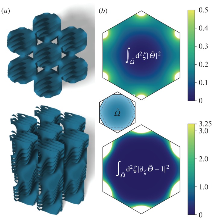
(a) The HN phase consists of a nested array of coherently rotating helical bundles, close packed into a hexagonal lattice and is given by level sets of the phase field  . The centres of the bundles are simple zeroes in the function Θhex(ζ), while branch point singularities at the corners of the fundamental hexagon diverge as ζ−1/2. (b) The compression energy for this phase field can be broken into two components
  (top) and
  (bottom). The inset shows the domain of integration,
  .
.
4.2. The energetics
The Landau–de Gennes free energy, equation (2.2), recast for the phase-field ansatz
ϕ = Re[Θ(w) e−iq0z] penalizes deviations of the layer normal from the ideal cholesteric director field, n = cos(q0z)ex + sin(q0z)ey, in the compression term Fcomp = B|∇ϕ − n|2. The compression energy density can be split into two components with ∇ϕ ⊥ n and ∇∥ ⊥ n, which, upon integrating out the director field, yield 
 and
and  respectively. The Landau–de Gennes free energy per volume is
 |
4.6 |
where A is the total area of one unit cell of the lattice and  denotes the area occupied by the smectic phase.
By construction, both of the trial phases have a simple zero at the centre of each bundle, yet deviations from linearity with growing bundle radius combined with the divergences contribute to the compression energy, as these are the locales where the director field, corresponding to the layer normal deviates most from the ideal cholesteric. In the case of divergences, the layer normal traces out a helicoid of the opposite chirality and at the core of the divergence, the director would yield a helicoid of opposite handedness of the underlying cholesteric. These are points at which the smectic order breaks down, melting to the cholesteric. These melted regions have cholesteric energy proportional to their volume, giving the morphology of bulk phases the flavour of a packing problem.
The magnitude of the energies follows from the higher order corrections to the Taylor expansions of  near centres of the bundles and the divergences. Near the simple zeroes, the expansions for the square and hexagonal lattices are given, respectively, by
  and
and 
 , while in the vicinity of the poles, the Taylor series are, respectively,
 and
and 
 , where p = 31/4/khex ≈ 0.412. It is clear that both terms will contribute to a higher compression free energy for the square lattice, thus we confine the remainder of our analysis to the hexagonal case. From the Taylor expansions near the zeroes and poles of the hexagonal lattice, the two components of the compression energy are
 |
4.7 |
where ε is the filling fraction (figure 2b). Thus, the total free energy for the hexagonal HN phase is
 |
4.8 |
5. Discussion
5.1. The phase diagram
Both the HN phase and the TGB phase condense from a higher temperature cholesteric, but the morphology of the HN phase is predicated upon having a higher chirality than is necessary to create the most highly chiral π/2 TGB phase. As the two constructions for the two phases follow from the same Landau theory, a phase diagram containing the two can be constructed. It behoves us to introduce a new non-dimensional parameter space,  and
and  which yield free energy densities for the TGB and HN phases, respectively, given by
 |
5.1 |
and
 |
5.2 |
where κG = λ/ξ is the Ginzburg parameter for the system, the TGB parameters are the turning angle, α and m, the solution to  and the HN parameters are the fraction of each unit cell occupied by smectic phase, ε and the hexagonal parameter,
  . The border between the TGB phase and the cholesteric is given by the upper critical chirality
  , but the HN phase is stable for lower chiralities. The phase selection criterion compares the lowest of the TGB energies for all values of rotation angle α to the lowest HN energy for all possible filling fractions, ε. The phase diagram is three dimensional with axes along the non-dimensional chirality,
  , reduced temperature
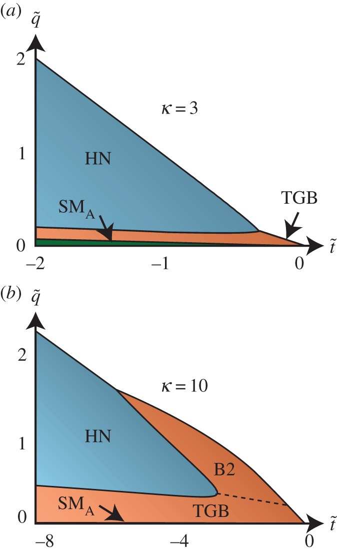
  and the Ginzburg parameter, κG. Slices with constant κG are shown in figure 3a.
Figure 3.
Phase diagrams for the chiral smectic-A* phase depend on the reduced temperature,  , reduced chirality
  and Ginzburg parameter κG = λ/ξ for the molecules. The phase boundary between the TGB and chiral nematic phases occurs at the upper critical chirality, qc2, while the onset of the HN phase occurs for lower reduced temperature and a finite, non-zero reduced chirality. (a) The phase diagram for a Ginzburg parameter κG = 3. (b) For higher values of the Ginzburg parameter, the critical point for the onset of the HN phase moves deeper into the TGB phase. This leaves room for other high-temperature bent-core smectic phases, such as B2, from which HN experimentally condenses.
The most salient feature of this phase diagram is that the HN phase only becomes stable above a critical chirality, which is smaller than qc2 and always occurs at lower reduced temperature than the zero chirality TGB/smectic/cholesteric triple point. As the Ginzburg parameter increases, the reduced temperature becomes lower and the TGB phase becomes reentrant upon increasing reduced chirality (figure 3b). Although this feature is unusual, it should be noted that in real systems the HN phase condenses from a higher temperature B2 phase of concentric cylindrical shells with a helical twist in the director field. This phase has not been included in our description and may account for the discrepancy.
5.2. Conclusion and future directions
We have presented a new continuum description for the smectic layer structure of the TGB phase, which features a continuously tunable angle θ, the angle of rotation of the smectic layers across each grain boundary. This phase is one minimizer of the chiral Landau–de Gennes free energy. The HN phase is another minimizer of the same free energy, stable for higher chiralities than the TGB phase. There is one set of parameters for which the π/2 TGB phase and the square lattice description of the HN phase have identical smectic layers, although the underlying cholesteric reorients between the two phases. Our united description allows us to create a complete phase diagram for the Landau–de Gennes energy for chiral smectics-A. We demonstrate that the HN phase is generally stable for higher values of the reduced chirality and extends below the lower critical chirality of the TGB phase and into the cholesteric phase. This is analogous to the A* phase of helimagnets, which may be described by a similar Landau theory. Further, a complete description would include other bent-core smectic phases, such as B2, and may shed light on exotic magnetic states.
Endnote
Note that  For
For 
 the integrals of the x- and y-components of the gradient of the phase field simplify as follows,

 , likewise
  .
.
Competing interests
We declare we have no competing interests.
Funding
This work was supported in part by NSF grant no. DMR1262047 (R.D.K.). This work is also partially supported by a Simons Investigator grant from the Simons Foundation to R.D.K. G.P.A. was supported in part by the UK EPSRC through grant no. EP/N007883/1.
References
- 1.Bouligand Y, Livolant F. 1984. The organization of cholesteric spherulites. J. Phys. 45, 1899–1923. ( 10.1051/jphys:0198400450120189900) [DOI] [Google Scholar]
- 2.Bouligand Y, Denefle JP, Lechaire JP, Maillard M. 1985. Twisted architectures in cell-free assembled collagen gels: study of collagen substrates used for cultures. Biol. Cell. 54, 143–162. ( 10.1111/j.1768-322X.1985.tb00389.x) [DOI] [PubMed] [Google Scholar]
- 3.Gaill F, Bouligand Y. 1987. Supercoil of collagen fibrils in the integument of Alvinella, an abyssal annelid. Tissue Cell 19, 625–642. ( 10.1016/0040-8166(87)90070-X) [DOI] [PubMed] [Google Scholar]
- 4.Hall DM, Bruss IR, Barone JR, Grason GM. 2016. HUL Access/2.0. Nat. Mater. 15, 727–732. ( 10.1038/nmat4598) [DOI] [PubMed] [Google Scholar]
- 5.Renn S, Lubensky TC. 1988. Abrikosov dislocation lattice in a model of the cholesteric to smectic A transition. Phys. Rev. A 38, 2132–2147. ( 10.1103/PhysRevA.38.2132) [DOI] [PubMed] [Google Scholar]
- 6.Link DR, Natale G, Shao R, Maclennan JE, Clark NA, Körblova E, Walba DM. 1997. Spontaneous formation of macroscopic chiral domains in a fluid smectic phase of achiral molecules. Science 278, 1924–1927. ( 10.1126/science.278.5345.1924) [DOI] [PubMed] [Google Scholar]
- 7.Dozov I. 2001. On the spontaneous symmetry breaking in the mesophases of achiral banana-shaped molecules. Europhys. Lett. 56, 247–253. ( 10.1209/epl/i2001-00513-x) [DOI] [Google Scholar]
- 8.Earl DJ, Osipov MA, Takezoe H, Takanishi Y, Wilson MR. 2005. Induced and spontaneous deracemization in bent-core liquid crystal phases and in other phases doped with bent-core molecules. Phys. Rev. E 71, 021706 ( 10.1103/PhysRevE.71.021706) [DOI] [PubMed] [Google Scholar]
- 9.Takanishi Y, Shin GJ, Jung JC, Choi SW, Ishikawa K, Watanabe J, Takezoe H, Toledano P. 2005. Observation of very large chiral domains in a liquid crystal phase formed by mixtures of achiral bent-core and rod molecules. J. Mater. Chem. 15, 4020–4024. ( 10.1039/b507875j) [DOI] [Google Scholar]
- 10.Sekine T, Niori T, Watanabe J, Furukawa T, Choi SW, Takezoe H. 1997. Spontaneous helix formation in smectic liquid crystals comprising achiral molecules. J. Mater. Chem. 7, 1307–1309. ( 10.1039/A702026K) [DOI] [Google Scholar]
- 11.Sekine T, Niori T, Sone M, Watanabe J, Choi SW, Takanishi Y, Takezoe H. 1997. Origin of helix in achiral banana-shaped molecular systems. Jpn. J. Appl. Phys. 36, 6455–6463. ( 10.1143/JJAP.36.6455) [DOI] [Google Scholar]
- 12.Thisayukta J, Takezoe H, Watanabe J. 2001. Study on helical structure of the B-4 phase formed from achiral banana-shaped molecule. Jpn. J. Appl. Phys. 40, 3277–3287. ( 10.1143/JJAP.40.3277) [DOI] [Google Scholar]
- 13.Niwano H, Nakata M, Thisayukta J, Link DR, Takezoe H, Watanabe J. 2004. Chiral memory on transition between the B2 and B4 phases in an achiral banana-shaped molecular system. J. Phys. Chem. B 108, 14 889–14 896. ( 10.1021/jp0311355) [DOI] [Google Scholar]
- 14.Livolant F, Bouligand Y. 1989. Freeze-fractures in cholesteric mesophases of polymers. Mol. Crystals Liquid Crystals 166, 91–100. ( 10.1080/00268948908037140) [DOI] [Google Scholar]
- 15.Hough LE. et al 2009. Helical nanofilament phases. Science 325, 456–460. ( 10.1126/science.1170027) [DOI] [PubMed] [Google Scholar]
- 16.de Gennes P. 1972. Analogy between superconductors and smectics A. Solid. State. Commun. 10, 753–756. ( 10.1016/0038-1098(72)90186-X) [DOI] [Google Scholar]
- 17.London F, London H. 1935. The electromagnetic equations of the supraconductor. Proc. R. Soc. Lond. A 149, 71–88. ( 10.1098/rspa.1935.0048) [DOI] [Google Scholar]
- 18.Kamien RD. 2001. Decomposition of the height function of Scherk's first surface. Appl. Math. Lett. 14, 797–800. ( 10.1016/S0893-9659(01)00046-5) [DOI] [Google Scholar]
- 19.Santangelo CD, Kamien RD. 2006. Elliptic phases: a study of the nonlinear elasticity of twist-grain boundaries. Phys. Rev. Lett. 96, 137801 ( 10.1103/PhysRevLett.96.137801) [DOI] [PubMed] [Google Scholar]
- 20.Santangelo CD, Kamien RD. 2007. Triply periodic smectic liquid crystals. Phys. Rev. E 75, 011702 ( 10.1103/PhysRevE.75.011702) [DOI] [PubMed] [Google Scholar]
- 21.Matsumoto EA, Alexander GP, Kamien RD. 2009. Helical nanofilaments and the high chirality limit of smectics A. Phys. Rev. Lett. 103, 257804 ( 10.1103/PhysRevLett.103.257804) [DOI] [PubMed] [Google Scholar]


