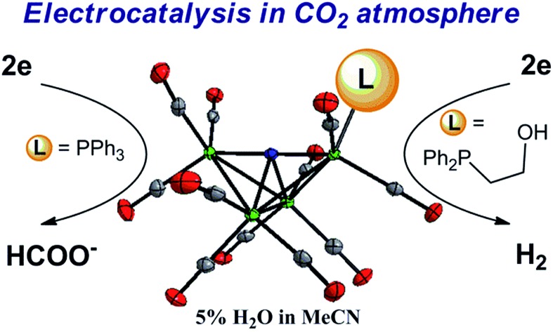
 A proton shuttle in the second coordination sphere of [Fe4N(CO)12]– promotes H2 evolution over formate formation from CO2.
Abstract
Proton relays are known to increase reaction rates for H2 evolution and lower overpotentials in electrocatalytic reactions. In this report we describe two electrocatalysts, [Fe4N(CO)11(PPh3)]– (1–) which has no proton relay, and hydroxyl-containing [Fe4N(CO)11(Ph2P(CH2)2OH)]– (2–). Solid state structures indicate that these phosphine-substituted clusters are direct analogs of [Fe4N(CO)12]– where one CO ligand has been replaced by a phosphine. We show that the proton relay changes the selectivity of reactions: CO2 is reduced selectively to formate by 1– in the absence of a relay, and protons are reduced to H2 under a CO2 atmosphere by 2–. These results implicate a hydride intermediate in the mechanism of the reactions and demonstrate the importance of controlling proton delivery to control product selectivity. Thermochemical measurements performed using infrared spectroelectrochemistry provided pKa and hydricity values for [HFe4N(CO)11(PPh3)]–, which are 23.7, and 45.5 kcal mol–1, respectively. The pKa of the hydroxyl group in 2– was determined to fall between 29 and 41, and this suggests that the proximity of the proton relay to the active catalytic site plays a significant role in the product selectivity observed, since the acidity alone does not account for the observed results. More generally, this work emphasizes the importance of substrate delivery kinetics in determining the selectivity of CO2 reduction reactions that proceed through metal–hydride intermediates.
Introduction
Selectivity continues to be a challenge in the design of electrocatalysts for production of fuels from CO2.1 We have previously proposed that the four-iron butterfly-shaped cluster, [Fe4N(CO)12]– promotes selective formation of formate over either CO or H2 formation because the reaction proceeds through catalytic intermediates that are not nucleophilic enough to interact directly with CO2 to promote C–O bond cleavage, or hydride transfer to H+ to afford H2.2 We further proposed that the key intermediate which transfers H– to CO2 is [HFe4N(CO)12]–. Our evidence for existence of this intermediate species included electrochemical signatures, a crystal structure and infrared spectroelectrochemical (IR-SEC) data that indicated a modest hydricity for [HFe4N(CO)12]– of 15.5, or 49 kcal mol–1, in water or MeCN, respectively. However, more evidence is needed to definitively confirm the existence and role of [HFe4N(CO)12]– in formate production.
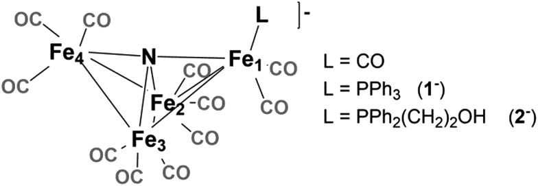
Accordingly, we installed a proton shuttle with weak acidity in the vicinity of the proposed location of the hydride: [Fe4N(CO)11(PPh2(CH2)2OH)]– (2–, Chart 1). We now describe that selective H2 production afforded by this structural modification must arise from proximity of the relay to the intermediate hydride. This is confirmed using the control, [Fe4N(CO)11(PPh3)]– (1–), which produces exclusively formate.
Chart 1. [Fe4N(CO)12]–. The “butterfly hinge” bond is Fe2–Fe3. The “butterfly wing” bonds are from Fe4 and Fe1 to Fe2 and Fe3. The “wingtip” atoms are Fe4 and Fe1.
Proton relays have previously been employed to direct selectivity in the reduction of small molecules. In one example, selectivity of CO formation from CO2 reduction was improved using iron–porphyrin complexes with phenol pendants.3,4 In the absence of this outer coordination sphere effect, mixtures of CO, H2 and formate had previously been obtained. Selectivity has also been controlled by carboxylic acid proton relays in both corrole5 and porphyrin6 compounds: and there, O2 reduction to H2O is promoted over H2O2 formation.
Proton relays also enhance rates, decrease overpotentials and promote already selective reactions.7,8 For instance, molecular electrocatalysts with pendant amine bases generate hydrogen with up to 106 000 turnovers per s,9 and “Hangman” porphyrin complexes exhibit lowered proton reduction overpotentials and increased rates.10 Biologically inspired 2Fe–2S clusters incorporate various secondary sphere pendant bases to achieve fast (TOF = 58 000 s–1) H+ reduction and operate at overpotentials as low as –0.51 V.11 The reverse reaction can also be assisted by a proton relay: for example, a molecular Fe catalyst for hydrogen oxidation is catalytic when 1 (TOF = 34 s–1) or 2 (TOF = 290 s–1) proton relays are present.7
Pendant bases are also known to facilitate C–H bond-making and breaking reactions. As examples, a series of Ni(ii) compounds with amine bases catalyze formate oxidation at 16 s–1,12via proton transfer from formate to a pendant amine, and in another example, an 2Fe–2S cluster with pendant amine promotes non-catalytic sp3-hybridized C–H bond activation.13
Results and discussion
Synthesis of compounds
The phosphine-substituted cluster [Na(diglyme)2][Fe4N(CO)11(PPh3)] (referred to as Na-1, or 1–) was synthesized by reflux of one equivalent of PPh3 with [Na(diglyme)2][Fe4N(CO)12] in THF, following a modified version of a reported procedure.14 Hydroxyl-containing [Na(diglyme)2][Fe4N(CO)11(Ph2P(CH2)2OH)] (Na-2, or 2–) was synthesized by reflux of [Na(diglyme)2][Fe4N(CO)12] with 1.4 equivalents of Ph2P(CH2)2OH for 16 hours. Upon workup, 2– was obtained in 49% yield. When less Ph2P(CH2)2OH was used, the reaction did not go to completion, as indicated by both 31P NMR and IR (νCO) spectroscopic analyses performed on aliquots analyzed during the reaction.
Each of the clusters, 1– and 2–, were characterized by 1H and 31P NMR, and by IR spectroscopy, and combustion analysis which confirmed compound purity. The 31P NMR spectra each show a single sharp resonance approximately 70 ppm downfield from the free phosphine ligand. The signal for 2– is at 49 ppm (Ph2P(CH2)2OH is at –23 ppm) and the signal for 1– is at 67 ppm (PPh3 is at –5 ppm). Similarly, PPN[Fe4N(CO)11(PMe2Ph)] was previously observed at 35 ppm (PMe2Ph is at –44 ppm).14a,15 IR spectroscopic measurements on phosphine-substituted clusters each showed 4 absorption bands compared with 2 bands in [Fe4N(CO)12]–. This is consistent with the expected decrease in molecular symmetry, from approximately C2v to Cs, upon ligand substitution. The IR spectra further indicate that the bands fall between 2038 and 1964 cm–1 for both 1– and 2–, and are at lower energy than in [Fe4N(CO)12]–. We ascribe this to the weaker π-accepting ability of the phosphine ligand compared with the CO ligand.
Solid state structures
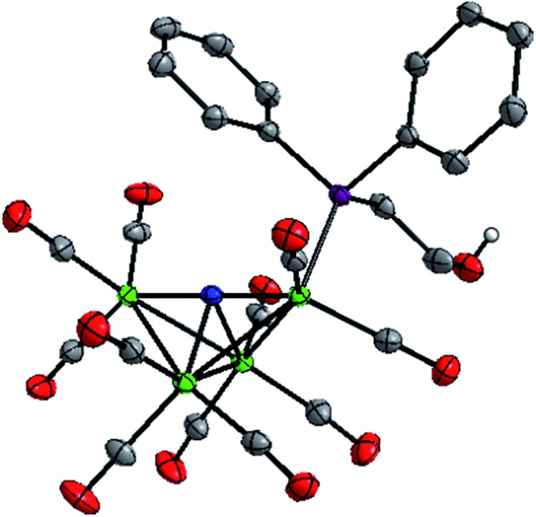
To enable crystal growth, the tetraethylammonium (Et4N+) salts of Na-1 and Na-2 were prepared, and solid state structures of Et4N-1 and Et4N-2 were determined (Fig. 1 and S1, Tables S1 and S2†). The structure of PPN-1 has been reported (PPN = bis(triphenylphosphine)-iminium).14b Comparison of Et4N-1 and Et4N-2 reveals that 1– has a longer Fe(1)–P bond, 2.2205(5) Å, than 2–, which is 2.2028(6) Å (the Fe(1)–P bond in PPN salt of 1– is similar, 2.217(2) Å). This result is consistent with a steric effect that correlates with Tolman cone angles for PPh3 and Ph2PCH2CH3 (used to approximate Ph2P(CH2)2OH), which are 145° and 140°, respectively.16 We also observed that replacement of CO by phosphine ligand has minimal impact on the Fe(1)–N bond lengths in both 1– and 2–. Likewise, the average lengths of the 4 Fe–Fe “butterfly wing” bonds (2.6064(14), 2.607(2), 2.613(2), and 2.6052(11) Å, for Et4N[Fe4N(CO)12], PPN-1, Et4N-1, and Et4N-2, respectively) are not notably affected by substitution of one CO for phosphine. In contrast, the Fe(2)–Fe(3) bonds associated with the “butterfly hinge” do vary with the electron donating properties of the ligand: for Et4N[Fe4N(CO)12], Et4N-1, and Et4N-2, the bond lengths are 2.5065(7), 2.5029(8), and 2.4790(5), respectively. The Fe–Fe hinge bond in 2–, with the most donating of the phosphines, is shortest.
Fig. 1. Solid state structure of 2– in Et4N-2. Grey, blue, red, green, and purple ellipsoids represent C, N, O, Fe and P atoms, respectively. H atoms except OH proton omitted, ellipsoids at 50%.
Electrochemical measurements under N2
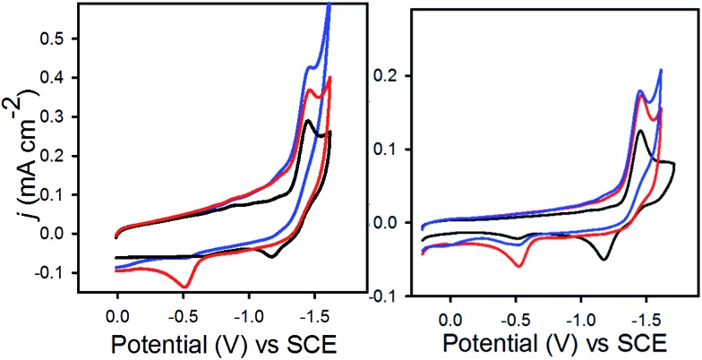
In 0.1 M Bu4NPF6 MeCN solution under 1 atm dinitrogen, at 0.1 V s–1, 1– displayed an irreversible reduction event at –1.45 V vs. SCE, and 2– displayed a similar irreversible event at –1.47 V (Fig. 2). These potentials are shifted cathodically compared with the corresponding event for [Fe4N(CO)12]–, which is reversible with E1/2 = –1.23 V, and Epc = –1.25 V in MeCN.17 The CV for 2– has an additional feature at –0.45 V which appears on the oxidative scan due to protonation of 2– by the proton relay to give (H-2)–. We have previously synthesized HFe4N(CO)12, and observed the [HFe4N(CO)12]–/0 couple at –0.45 V vs. SCE in MeCN.17 In the present work, water in MeCN is sufficiently acidic to protonate the reduced clusters, 12– and 22–, to afford the hydrides, (H-1)– and (H-2)–, which are then oxidized on the return scan (Fig. 2, red traces). To confirm that the observed reduction events for 1– and 2– in 0.1 M Bu4NPF6 MeCN solution correspond to solution based, non-catalytic processes plots of peak current (ip) vs. scan rate (υ1/2) for both compounds were constructed (Fig. S2†). The straight lines indicate a diffusion-controlled event, according to the Randles–Sevcik equation (eqn (1)):18
| ip = (2.686 × 10⁵)n3/2D1/2AC*υ1/2 | 1 |
Fig. 2. (Left) CV's of 0.3 mM 1–, and (right) 0.1 mM 2–. Recorded in 0.1 M Bu4NPF6 MeCN, 1 atm N2 (black); in 0.1 M Bu4NPF6 MeCN/H2O (95 : 5), 1 atm N2 (red); in 0.1 M Bu4NPF6 MeCN/H2O (95 : 5), 1 atm CO2 (blue). Scan rate 0.1 V s–1.
In eqn (1), n is the number of electrons, A the electrode area (cm2), D the diffusion coefficient for the complex (cm2 s–1), C* the concentration of complex (M), and υ the scan rate (V s–1). CPE experiments were conducted in 0.1 M Bu4NPF6 MeCN/H2O (95 : 5) under 1 atm N2 at –1.4 V. Using either catalyst 1– or 2– the Faradaic efficiency (FE) for H2 evolution was 70 ± 4 and 96 ± 6%. H2 was quantified by GC-TCD analysis of the headspace.
Electrochemical measurements under CO2
When solutions were sparged with CO2, an increase in current was observed with 1–, but not with 2– (Fig. 2). CPE experiments were conducted in 0.1 M Bu4NPF6 MeCN/H2O (95 : 5) under 1 atm CO2 at –1.4 V (Table 1). Using 1–, FE for formate production was 61% and for H2 production was 36%. Formate was quantified by proton NMR spectroscopy. The H2 production arises from a background reaction at the GC electrode, and the charge passed for H2 production is the same as the amount of charge passed during control experiments containing no catalyst. CPE experiments with 1– conducted under CO2 in 0.1 M Bu4NPF6 MeCN solutions containing no water did not pass significant charge, and no H2, CO or formate were detected. CPE measurements performed with 2– in 0.1 M Bu4NPF6 MeCN/H2O (95 : 5) under 1 atm CO2 afforded H2, and no detectable CO2 reduction products. We attribute this to the proton relay in 2– which facilitates protonation of the hydride intermediate. As a further control experiment, CPE measurements were performed with 1– in 0.1 M Bu4NPF6 MeCN/H2O (95 : 5) containing 0.2% (1000 molar equivalents) of EtOH, under 1 atm CO2: formate production persisted with 58% FE. In all experiments some of the H2 detected arises from background production by the glassy carbon electrode, but the charge passed during experiments with catalyst is greater than in the control experiment containing no catalyst (Table 1, Fig. S3†). IR spectra collected after electrolysis showed no change to the catalysts (Fig. S3†).
Table 1. CPE experiments at –1.4 V vs. SCE in 0.1 M Bu4NPF6 MeCN/H2O (95 : 5) under 1 atm CO2 over 50 min, with 0.1 mM catalyst. Each experiment performed three times.
| Catalyst | q (C) | TON HCO2– | TON H2 | FE (%) HCO2– | FE (%) H2 |
| 1 – | 4 ± 2 | 5.4 ± 3 | 3.3 ± 2 | 61 ± 6 | 36 ± 3 |
| 2 – | 16 ± 4 | Na | 40 ± 5 | <3 | 97 ± 5 |
| None | 2.7 | Na | Na | Na | 28 ± 6 |
Mechanism of CO2 reduction
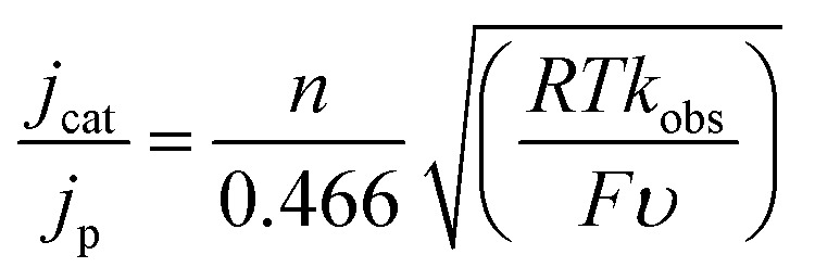
The mechanism of the reduction of CO2 by 1– in 0.1 M Bu4NPF6 MeCN/H2O (95 : 5) was analysed further by CV. We found that the reaction is first order in [1–] and first order in protons and CO2 (Fig. S4†). We also measured the rate of formate formation by 1– using a model described by eqn (2).19
 |
2 |
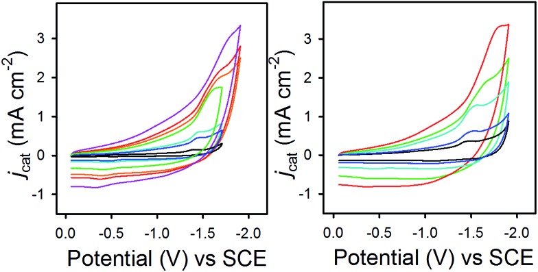
In eqn (2), jcat/jp is the ratio of catalytic to noncatalytic current density (mA cm–2), R is the universal gas constant, T is temperature (K), F is Faraday's constant (C mol–1), n is moles of electrons, υ is the scan rate (V s–1), and kobs is the observed rate constant. The peak current density for reduction of 1– to 12– in the presence (jcat, Fig. 3, left) and absence (jp, Fig. 3, right) of CO2 was determined over a series of scans where jcat is independent of scan rate: 0.5 to 0.9 V s–1 (Fig. S5† left). Using eqn (2), kobs is 3.3 s–1.
Fig. 3. CVs in 0.1 M Bu4NPF6 MeCN/H2O (95 : 5) recorded with varied scan rates, (left) for 1– under 1 atm CO2 and (right) for 0.1 mM 1– under N2.
Taken together, these experiments illustrate that a proton relay on the [Fe4N(CO)12]– reduction electrocatalyst changes product selectivity such that H2 production occurs instead of C–H bond formation with CO2 to give formate. We have previously reported a mechanism for CO2 reduction selectively to formate by the unfunctionalized cluster, [Fe4N(CO)12]–,2 and the data acquired for this present report support an analogous mechanism for CO2 reduction by 1–: reduction of 1– to 12– is followed by protonation to afford the reduced hydride, (H-1)–. Subsequent reaction of (H-1)– with CO2 provides formate and 1. Reduction of 1 back to 1– is facile under the reaction conditions (–1.4 V) since the 10/– couple is estimated at approximately +0.4 V. An accurate value for this couple has not been obtained since the oxidation of 1– (and of [Fe4N(CO)12]–) is irreversible.
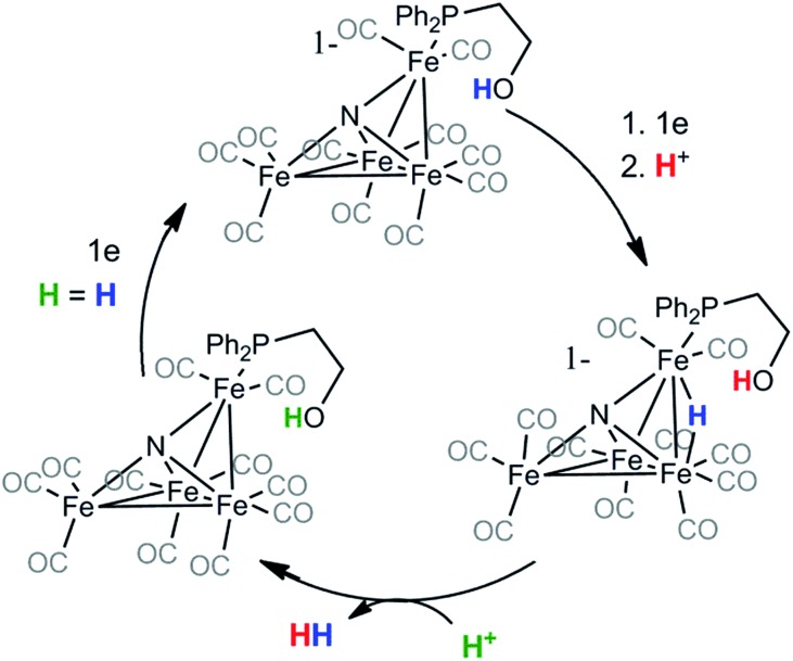
Based on the change in product selectivity in the presence of the attached ethanol relay in 2–, we conclude that the proton relay must supply a second equivalent of H+ necessary to generate H2 from (H-2)– (Scheme 1). Our results do not necessarily preclude the possibility that hydrogen bonding interactions by the hydroxyl proton are promoting the observed selectivity but they are consistent with proton relay behavior. In addition, IR-SEC experiments in MeCN on 2– generate small amounts of H2 even without added acid (vide infra): this suggests the proton relay can also protonate 22– in the first step. These observations, along with the kinetic experiments performed using CV and the results of our previously published work on [Fe4N(CO)12]–,2,17 lead to a proposed mechanism for H2 formation by 2– (Scheme 1).
Scheme 1. H = H is included in the final step of the catalytic cycle to indicate that the new proton will play the same role in a subsequent cycle.
Mechanism of H+ reduction
As further support for the role of the proton relay in 2–, we determined the relative rates of proton reduction to H2 using 1– and 2– under an N2 atmosphere, in 0.1 M Bu4NPF6 MeCN/H2O (95 : 5). The order of reaction with respect to catalysts 1– and 2– under N2 was found to be one (Fig. S6†). With respect to protons, the reaction is second order in each case (Fig. S7†). Rate constants for proton reduction under an N2 atmosphere were also obtained for 1– and 2– using a series of experiments in the presence (Fig. 3 right and S8†) and absence (Fig. S2†) of protons, where jcat was independent of scan rate between 0.3 and 1 V s–1, and between 0.5 V s–1 and 1 V s–1 for 1– and 2– respectively (Fig. S5 right and S8 right†). Eqn (2) yielded rate constants for 1– and 2– which we calculated with the same overpotential, i.e. at –1.51 V and –1.53 V, respectively: the rates of H2 production are 2.0 ± 0.5 s–1, and 4.2 ± 0.1 s–1, respectively. These results demonstrate that the hydroxyl group enables 2– to catalyze reduction of protons to H2 two times faster than 1–.
Thermochemical measurements for 1–
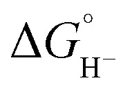
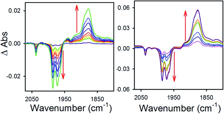
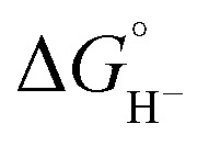
To obtain more information about the reactivity of the proposed reduced hydride intermediate, (H-1)–, we determined the pKa and hydricity values for (H-1)– and determined the pKa for the proton relay in 2–. Hydricity is defined as the free energy for loss of H– from a metal complex, 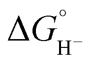 . When a –1.45 V potential was applied to a solution of 1– the νCO absorption bands associated with 1–, at 2038, 1987, 1972, and 1966 (sh) cm–1 decreased, and new features, ascribed to 12–, appeared at 1879, 1889 (sh), 1920, and 1942 (sh) cm–1 (Fig. 4, left). The isosbestic point is at 1955 cm–1.
Fig. 4. Difference absorbance spectra in 0.1 MBu4NPF6 MeCN electrolyzed at –1.45 V vs. SCE, of (left) 1– and (right) 1– with 1 equivalent (0.3 mM) of butyric acid.
Having generated 12–, we investigated its reaction with a weak acid to establish the pKa value for (H-1)–via the thermochemical cycle in eqn (3)–(6):
 |
3 |
| BuCO2H ⇌ BuCO2– + H+ pKa(BuCO2H) | 4 |
 |
5 |
| pKa = pKeq + pKa(BuCO2H) | 6 |
An IR-SEC experiment was performed on 1– in dry 0.1 M Bu4NPF6 MeCN solution containing 1 equivalent of butyric acid (BuCO2H, pKa = 22.7 in MeCN)22 under 1 atm of H2 (Fig. 4, right). The potential was held constant at –1.45 V vs. SCE to reduce 1– to 12–, and probe the subsequent reactivity of 12– with a weak acid. The resulting IR spectrum contained features at 1878, 1890 (sh), and 1918 (sh) cm–1. The isosbestic point was at 1926 cm–1, compared with 1955 cm–1 observed for the reduction of 1– to 12–. This suggests that no 12– is present and that conversion to (H-1)– occurred. No gas bubbles were observed, and this indicates that no H2 was evolved by protonation of (H-1)–. When a slightly stronger acid (benzoic acid; pKa = 20.7 in MeCN)23 was used, large gas bubbles formed rapidly inside the IR-SEC cell. When 10 equivalents of the weaker acid benzenesulfonamide (pKa = 24.6 in MeCN)22 were used, no H2 formed and the resulting spectra had the same isosbestic point (1955 cm–1) and features as 12– in dry MeCN (Fig. S9†). This provides the upper limit of 24.6 for the pKa of (H-1)–, and we estimate its value as 23.7 ± 1 (Table 2).
Table 2. Thermochemical parameters in MeCN, for (H-1)–, HCOO–, and H2.
The hydricity of (H-1)– was measured by bracketing the value of Keq for eqn (7), and employing the thermochemical cycle outlined in eqn (7)–(11):
 |
7 |
| H+ + A– ⇌ HA 1/Kacid | 8 |
 |
9 |
 |
10 |
 |
11 |
Two limiting cases exist – one where the production of H2 is heavily favored (Keq > 10), and one where the hydride intermediate is formed but does not react with excess acid to form H2 (Keq < 0.1). In the IR-SEC experiment described above, under 1 atm H2, these two limiting cases were observed. Use of 1 equivalent of benzoic acid immediately afforded H2 and so the value of Keq (eqn (7)) can be estimated as Keq > 10, which gives hydricity of (H-1)–, 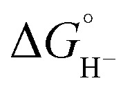 , as < 46 kcal mol–1. In a second experiment 1 equivalent of butyric acid afforded the hydride (H-1)– quantitatively (Fig. 4, right). If 10 equivalents of butyric acid were used, near-complete conversion to the hydride is accompanied by the slow formation of H2, as well as some peaks that correlate to 1– (Fig. S9†). This provides an estimate for Keq as < 0.5, and a limit of
 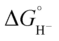 > 45. The hydricity of (H-1)– is thus 45–46, or 45.5 ± 0.5 kcal mol–1 (Table 2).
The hydricity of formate in MeCN is 44 kcal mol–1.21 This means that formate production by (H-1)– is thermodynamically unfavorable by 1.5 kcal mol–1. However it has been shown that hydricity values decrease sharply in aqueous solution,2,24 and that the addition of 5% water to the CV and CPE experiments as described is sufficient to promote thermochemically favorable C–H bond formation with CO2 by (H-1)–.
Thermochemical measurements for 2–
We could not perform experiments to determine the pKa (H-2)– since the proton relay interferes with our ability to control the acidity of available protons during IR-SEC experiments. However, based on the similar reduction potentials for the two clusters, combined with their otherwise very similar structures and physical properties, we estimate similar pKa and 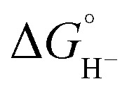 values for (H-2)–: 23.7 ± 1 and 45.5 ± 0.5 kcal mol–1, respectively. DuBois and coworkers have previously demonstrated that complexes with minor structural modifications exhibit a strong correlation between reduction potential and hydricity values,25 and between reduction potential and pKa values.26 In our own work we see a correlation with reduction potential and hydricity values over the series of clusters: [Fe4N(CO)12]–,22–, and [Fe4C(CO)12]2–.27
To probe the pKa of the hydroxyl group, we first independently synthesized the deprotonated alkoxide Ph2P(CH2)2OLi, and characterized this using 1H, 31P and 13C NMR spectroscopy. We then used 1H NMR (CD3CN) to estimate two limits for the pKa of the hydroxyl proton in PPh2(CH2)2OH (Fig. S10†). In two separate experiments, a solution of PPh2(CH2)2OH in CD3CN was combined with 1 equivalent of either NaOPh (pKa for PhOH is 29.1 in MeCN)28 or NaHMDS (pKa of NaHMDS is 41 in MeCN; NaHMDS is sodium hexamethyldisilazide).29,30 Proton NMR spectroscopy indicated that deprotonation occurred with NaHMDS but not with NaOPh. Therefore, we estimated for PPh2(CH2)2OH that 29 < pKa < 41 in MeCN. Based on eqn (7)–(11), we can calculate from these measurements that ΔG° (eqn (7)) falls between 9.23 and 25.7 kcal mol–1 and predict that the reaction between (H-1)– (or (H-2)–) is unfavorable in MeCN solution. Under the conditions of the CV and CPE experiments, which are in MeCN/H2O (95 : 5) we can estimate that ΔG° (eqn (7)) is even less favorable because we know that 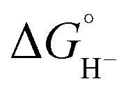 values for our iron clusters drop more significantly than
  values for H2 when moving from MeCN into water.2
Previous work involving immobilized proton shuttles has discussed the effect where Brönsted acidic groups attached to a catalyst create a large local proton concentration near the catalyst that has an effective pKa far lower than the measured pKa of the attached acidic functional group.4 Our results obtained measuring the pKa values for PPh2(CH2)2OH and for (H-2)– and (H-1)– indicate that the measured pKa values alone cannot account for the observed reactivity where H2 is produced by 2– while formate is produced by 1–. We conclude that the proximity of the proton relay to the position of the Fe hydride must be a major factor in promoting H2 formation over reaction of (H-2)– with CO2. In addition, the apparently high pKa of PPh2(CH2)2OH could explain why H2 evolution rates we observed with 2– are only enhanced two-fold compared with rates observed for 1– under N2 atmosphere: this is significantly less rate enhancement than observed by others who have employed proton shuttles to promote H2 production.
Summary and conclusions
We have shown that inclusion of a hydroxyl functional group as proton relay in the outer coordination sphere of [Fe4N(CO)12]– alters product selectivity so that only H2 is obtained. Formate is obtained selectively in the absence of a proton relay. These results provide further evidence for the existence of a reduced hydride intermediate, [HFe4N(CO)12]–, as the key species responsible for C–H bond formation with CO2 to yield formate selectively, in the [Fe4N(CO)12]– family of electrocatalysts. More generally, these results emphasize the importance of controlling the kinetics of substrate delivery in determining the selectivity of CO2 and H+ reduction reactions.
Experimental section
X-ray structure determinations
X-ray diffraction studies were carried out on either a Bruker SMART APEXII or a Bruker SMART APEX Duo diffractometer equipped with a CCD detector.31a Measurements were carried out at –183 °C using Mo Kα 0.71073 Å radiation. Crystals were mounted on a Kaptan Loop with Paratone-N oil. Initial lattice parameters were obtained from a least-squares analysis of more than 100 centered reflections; these parameters were later refined against all data. Data were integrated and corrected for Lorentz polarization effects using SAINT31b and were corrected for absorption effects using SADABS2.3.31c
Space group assignments were based upon systematic absences, E statistics, and successful refinement of the structures. Structures were solved by direct methods with the aid of successive difference Fourier maps and were refined against all data using the SHELXTL 5.0 software package.31d Thermal parameters for all non-hydrogen atoms were refined anisotropically. Hydrogen atoms, where added, were assigned to ideal positions and refined using a riding model with an isotropic thermal parameter 1.2 times that of the attached carbon atom (1.5 times for methyl hydrogens).
Other physical measurements
1H-NMR and 13C-NMR spectra were recorded at ambient temperature using a Varian 600 MHz spectrometer. Chemical shifts were referenced to residual solvent. 31P-NMR spectra were recorded on a Varian 300 MHz spectrometer at ambient temperature and referenced using an external H3PO4 standard (chemical shift of H3PO4 = 0 ppm). Quantitative measurement of H2 was performed on a Varian 3800 GC equipped with a TCD detector and a Carboxen 1010 PLOT fused silica column (30 m × 0.53 mm) (Supelco) using dinitrogen (99.999%, Praxair) as the carrier gas. H2 concentration was determined using a previously prepared working curve. Elemental analyses were conducted by University of California, Berkeley Microanalytical Labs.
Infra-red spectra were recorded in a sealed liquid cell on a Bruker Alpha Infra-red spectrometer. IR-SEC measurements were performed under 1 atm H2 (g), using an optically transparent thin layer solution IR cell fabricated by Prof. Hartl at University of Reading at UK, as described previously.32 In each experiment, electrochemical reduction of the species of interest was monitored by IR spectroscopy for a period of 2–15 min. Diffusion and mixing of the redox products, generated at the working and auxiliary electrodes in the IR cell was reasonably suppressed within the total experimental time. Concentrations of all acids used in IR-SEC measurements were either 0.3 mM or 3.0 mM, and at these low concentrations homoconjugation is negligible (see ESI† for further details).
Preparation of compounds
All manipulations were carried out using standard Schlenk or glove-box techniques under a dinitrogen atmosphere. Unless otherwise noted, solvents were deoxygenated and dried by thorough sparging with Argon (Praxair, 99.998%) gas followed by passage through an activated alumina column. Deuterated solvents were purchased from Cambridge Isotopes Laboratories, Inc., degassed and stored over activated 3 Å molecular sieves prior to use. [Et4N][Fe4N(CO)12]17 and PPh2(CH2)2OH33 were prepared using modified syntheses from the literature. All other reagents were purchased from commercial vendors and used without further purification.
[Na(diglyme)2][Fe4N(CO)11(PPh3)] (Na-1)
Na-1 was synthesized using a slight modification of a previously published literature method.14 [Na(diglyme)2][Fe4N(CO)12] (153 mg, 0.17 mmol) was dissolved in 10 mL of THF in a Schlenk flask under a nitrogen atmosphere, and 0.17 mmol of PPh3 (45.4 mg) was added. The Schlenk flask was fitted with a short reflux condenser and held at reflux temperature under active nitrogen for 16 hours. The reaction mixture was cooled to room temperature, half of the solvent was removed in vacuo, and 20 mL of hexane was added with stirring to precipitate a black powder. The mixture was allowed to settle before the supernatant was removed via cannula. 15 mL of degassed distilled water was used to wash the powder, which was dried under vacuum (121 mg, 66%). 1H NMR (C6D6): 7.95 (br m, 7.5H), 7.06 (br m, 7.5H), 2.97 (br s, 28H) ppm. 31P NMR (THF): 67 (s) ppm. Anal. calcd (found): C, 44.80 (44.43), H, 3.94 (3.59), N, 1.27 (1.69). IR (THF): νCO 2038 (w), 1966 (sh), 1972 (vs), 1987 (vs) cm–1. Crystals suitable for X-ray diffraction studies were obtained following salt metathesis of Na-1 with Et4NCl in diethyl ether. After filtration to remove NaCl the solvent was removed in vacuo, and Et4N-1 was crystallized from a concentrated hexane solution at –25 °C over one month, as brown crystals.
[Na(diglyme)2][Fe4N(CO)11(PPh2(CH2)2OH)] (Na-2)
We followed the procedure used to synthesize Na-1, but used 1.4 equivalents of PPh2(CH2)2OH and 1.0 equivalents of [Na(diglyme)2][Fe4N(CO)12]. After precipitation with hexane, the resulting black powder, Na-2 (150 mg, 49%), was filtered, dried, and stored in a dry box under 1 atm N2. 1H NMR (CDCl3): 0.88 (t, J = 7.32 Hz, 2H), 1.03 (t, J = 7.22 Hz, 2H), 3.41 (s, 12H), 3.58 (m, 8H), 3.65 (m, 8H), 7.43 (br m, 4H), 7.51(br m, 2H), 7.67 (br m, 4H) ppm. 31P NMR (THF) 49 (s) ppm. Anal. calcd (found) for Na-2•0.25THF: C, 42.06 (42.46), H, 4.18 (3.61), N, 1.29 (1.65). IR (THF): νCO 2036 (w), 1986 (vs), 1970 (vs), 1964 (sh) cm–1. Crystals suitable for X-ray diffraction studies were obtained following salt metathesis of Na-2 with Et4NCl in diethyl ether. After filtration to remove NaCl the solvent was removed in vacuo, and Et4N-2 was crystallized by diffusion of pentane into a THF solution.
PPh2(CH2)2OLi
A procedure analogous to one previously reported for deprotonating the closely related alcohol PPh2CH2C(Me)2OLi was followed.34 PPh2(CH2)2OH (16 mg, 0.07 mmol) was stirred for 1 hour under 1 atm N2 with 1 equivalent of lithium diisopropylamide (33 μL, 0.07 mmol, 2.0 M THF/heptane/ethylbenzene solution) in 2 mL of dry THF at 25 °C. After concentration of the solvent in vacuo, 3 mL of hexane was added to precipitate an off-white powder. This was allowed to settle, and then washed twice with 5 mL portions of hexanes and dried in vacuo. 1H NMR (CD3CN): 7.38 (br m, 4H), 7.30 (br m, 6H), 3.70 (br, 2H), 2.32 (t, J = 7.3 Hz, 2H) ppm. 13C NMR (C6D6): 137.73 (s, ipso Ph), 133.72 (d, J = 17 Hz, ortho Ph), 128.67 (m, Ph), 60.17 (br s, OCH2), 37.18 (br s, PCH2) ppm. 31P NMR (CD3CN): –24 ppm.
In situ deprotonation of PPh2(CH2)2OH by NaHMDS or PhOH
Stock solutions of 60 mM PPh2EtOH (13.8 mg in 1 mL of CD3CN) and 60 mM of base were used to prepare an NMR sample with 15 μmol of base and 15 μmol of PPh2(CH2)2OH. A proton NMR spectrum was recorded after 12 h.
Electrochemical measurements
Cyclic voltammograms were recorded under a dinitrogen (Praxair, 99.998%) atmosphere using a CH Instruments Electrochemical Analyzer Model 620D or 1100, a glassy carbon working electrode (CH Instruments, nominal surface area of 0.0707 cm2), a platinum wire auxiliary electrode, and a Ag/AgNO3 non-aqueous reference electrode with a Vycor tip. Reported potentials are all referenced to the SCE couple, and were determined using ferrocene as an external standard where E1/2 ferrocene/ferrocenium is +0.400 V vs. SCE in acetonitrile.35 The effect of adding 5% H2O to the acetonitrile referencing solution on the ferrocene/ferrocenium couple is minimal (18 mV, Fig. S11†). Bu4NPF6 was recrystallized from boiling anhydrous ethanol and dried under vacuum at 70 °C for 48 hours before use. Non-aqueous electrolyte solutions were stored over 3 Å molecular sieves which had been activated by heating under vacuum at 200 °C for at least 72 hours.
Controlled potential bulk electrolysis (CPE)
Controlled potential electrolysis (CPE) experiments were performed in a custom designed gas-tight glass cell under 1 atm of static dinitrogen (Praxair, 99.998%) or CO2, as needed. Solutions were sparged with the gas of interest prior to the commencement of the experiment. The counter electrode compartment was separated from the working electrode compartment by a glass frit of medium porosity. In a typical experiment, 18 mL of electrolyte solution were used in the working electrode compartment and 25 mL of electrolyte were used in the counter electrode compartment.
The working electrode was a glassy carbon plate (Tokai Carbon) with the nominal surface area immersed in solution of 8 cm2. The auxiliary electrode was a coiled Pt wire (BASi). CO2 was obtained from dry ice and transferred to experiments via cannula and tubing. Gas measurements were performed using a gas-tight syringe (Vici) to inject 50 μL to 100 μL gas samples into a Varian 3800 gas chromatogram equipped with a thermal conductivity detector. Gas samples were extracted from a sparged, septum-capped side arm on the working electrode compartment. No CO was detected. In between CPE experiments, the cell and working electrodes were sonicated in 5% v/v nitric acid for 10 min, rinsed, sonicated in methanol for 10 min, rinsed, and sonicated in water for 10 min.
Quantification of formic acid was performed using 1H NMR spectroscopy. An internal standard of a known amount of dimethylformamide, as a dilute solution in 100% C6D6, was prepared and sealed in a glass capillary tube. 500 μL of the CPE solution were injected into an NMR tube with the internal standard capillary. The integration of the 1H resonance at 7.65 ppm for DMF, was used to quantify formic acid produced (8.16 ppm).
Order with respect to catalyst
A 5.0 mM stock solution of catalyst in N2-sparged dry electrolyte was prepared and stored under N2. This stock solution was used for all CV experiments for that catalyst. An aliquot of catalyst was diluted to 0.05 mM with 5% degassed MilliQ water and 95% 0.1 M Bu4NPF MeCN solution. Successive additions of cluster stock solution were done and CVs recorded.
Order with respect to acid
Aliquots of a 20 mM benzoic acid stock solution in dry 0.1 M Bu4NPF6 MeCN were added to a 0.1 mM solution of 1– or 2–, also in dry 0.1 M Bu4NPF6 MeCN solution. Prior to the first addition and after each subsequent addition of acid, a CV was recorded. Acid blanks were collected in the absence of catalyst to ensure that background acid reduction did not occur at the glassy carbon electrode.
Supplementary Material
Acknowledgments
We thank the National Science Foundation for funding through the CAREER program (CHE-1055417). NDL thanks the U.S. Department of Education for partial support by a GAANN fellowship. CLB thanks ACS Project SEED for a summer stipend. LAB is an Alfred P. Sloan Foundation Fellow.
Footnotes
†Electronic supplementary information (ESI) available: Crystallographic data, electrochemical data. 1H-NMR data. CCDC 1418842 and 1418843. For ESI and crystallographic data in CIF or other electronic format see DOI: 10.1039/c5sc03169a
References
- Benson E. E., Kubiak C. P., Sathrum A. J., Smieja J. M. Chem. Soc. Rev. 2009;38:89. doi: 10.1039/b804323j. [DOI] [PubMed] [Google Scholar]
- Taheri A., Thompson E. J., Fettinger J. C., Berben L. A. ACS Catal. 2015;5:7140. [Google Scholar]
- Constentin C., Passard G., Robert M., Savéant J. M. J. Am. Chem. Soc. 2014;136:11821. doi: 10.1021/ja506193v. [DOI] [PubMed] [Google Scholar]
- Constentin C., Drouet S., Robert M., Savéant J. M. Science. 2012;338:90. doi: 10.1126/science.1224581. [DOI] [PubMed] [Google Scholar]
- Dogutan D. K., Stoian S. A., McGuire Jr R., Schwalbe M., Teets T. S., Nocera D. G. J. Am. Chem. Soc. 2011;133:131. doi: 10.1021/ja108904s. [DOI] [PubMed] [Google Scholar]
- Carver C. T., Matson B. D., Mayer J. M. J. Am. Chem. Soc. 2012;134:5444. doi: 10.1021/ja211987f. [DOI] [PubMed] [Google Scholar]
- Yang J. Y., Smith S. E., Liu T., Dougherty W. G., Hoffert W. A., Kassel W. S., DuBois M. R., DuBois D. L., Bullock R. M. J. Am. Chem. Soc. 2013;135:9700. doi: 10.1021/ja400705a. [DOI] [PubMed] [Google Scholar]
- Darmon J. M., Kumar N., Hulley E. B., Weiss C. J., Raugei S., Bullock R. M., Helm M. L. Chem. Sci. 2015;6:2737. doi: 10.1039/c5sc00398a. [DOI] [PMC free article] [PubMed] [Google Scholar]
- Helm M., Stewart M. P., Bullock R. M., DuBois M. R., DuBois D. L., DuBois D. L., Bullock R. M. Science. Eur. J. Inorg. Chem. 2011;2011;333:863. 1017. doi: 10.1126/science.1205864. [DOI] [PubMed] [Google Scholar]
- Graham D. J., Nocera D. G., Lee C. H., Dogutan D. K., Nocera D. G. Organometallics. J. Am. Chem. Soc. 2014;2011;33133:4994. 8775. [Google Scholar]
- Rauchfuss T. Acc. Chem. Res. 2015;48:2107. doi: 10.1021/acs.accounts.5b00177. [DOI] [PMC free article] [PubMed] [Google Scholar]
- Galan B. R., Schoffel J. J., Linehan J. C., Seu C., Appel A. M., Roberts J. A. S., Helm M. L., Kilgore U. J., Yang J. Y., DuBois D. L., Kubiak C. P. J. Am. Chem. Soc. 2011;133:12767. doi: 10.1021/ja204489e. [DOI] [PubMed] [Google Scholar]
- Zheng D., Wang N., Wang M., Ding S., Ma C., Darensbourg M. Y., Hall M. B., Sun L. J. Am. Chem. Soc. 2014;136:16817. doi: 10.1021/ja5078014. [DOI] [PubMed] [Google Scholar]
- (a) Gourdon A., Jeannin Y. J. Organomet. Chem. 1992;440:353. [Google Scholar]; (b) Zanello P., Laschi F., Cinquantini A., Pergola R. D., Garlaschelli L., Cucco M., Demartin F., Spalding T. R. Inorg. Chim. Acta. 1994;226:1. [Google Scholar]
- Mika L. T., Orha L., Farkas N., Horvath I. T. Organometallics. 2009;28:1593. [Google Scholar]
- Tolman C. Chem. Rev. 1977;77:313. [Google Scholar]
- Rail M. D., Berben L. A. J. Am. Chem. Soc. 2011;133:18577. doi: 10.1021/ja208312t. [DOI] [PubMed] [Google Scholar]
- (a) Zanello P., Inorganic Electrochemistry: Theory, Practice and Application, 2003, pp. 49–136. [Google Scholar]; (b) Bard A. J. and Faulkner L. R., Electrochemical Methods: Fundamentals and Applications, Johns Wiley and Sons, New York, 2nd edn, 2001. [Google Scholar]
- (a) Saveánt J. M., Vianello E. Electrochim. Acta. 1965;10:905. [Google Scholar]; (b) Saveánt J. M., Vianello E. Electrochim. Acta. 1967;12:629. [Google Scholar]; (c) Nicholson R. S., Shain I. Anal. Chem. 1964;36:706. [Google Scholar]; (d) McCrory C. C. L., Uyeda C., Peters J. C. J. Am. Chem. Soc. 2012;134:3164. doi: 10.1021/ja210661k. [DOI] [PubMed] [Google Scholar]; (e) Clark M. L., Grice K. A., Moore C. E., Rheingold A. L., Kubiak C. P. Chem. Sci. 2014;5:1894. [Google Scholar]
- Curtis C. J., Miedaner A., Ellis W. W., Dubois D. L. J. Am. Chem. Soc. 2002;124:1918. doi: 10.1021/ja0116829. [DOI] [PubMed] [Google Scholar]
- (a) Price A. J., Ciancanelli R., Noll B. C., Curtis C. J., Dubois D. L., Dubois M. R. Organometallics. 2002;21:4833. [Google Scholar]; (b) Miller A. J. M., Labinger J. A., Bercaw J. E. Organometallics. 2011;30:4308. doi: 10.1021/om200364w. [DOI] [PMC free article] [PubMed] [Google Scholar]
- Chantooni M. K., Kolthoff I. M. J. Phys. Chem. 1975;79:1176. [Google Scholar]
- Izutsu K., in Acid–base Dissociation Constants in Dipolar Aprotic Solvents, IUPAC Chemical Data Series No. 35, Blackwell Scientific, Oxford, 1990. [Google Scholar]
- (a) Matsubara Y., Fujita E., Doherty M. D., Muckerman J. T., Creutz C. J. Am. Chem. Soc. 2012;134:15743. doi: 10.1021/ja302937q. [DOI] [PubMed] [Google Scholar]; (b) Tsay C., Livesay B. N., Ruelas S., Yang J. Y. J. Am. Chem. Soc. 2015;137:14114. doi: 10.1021/jacs.5b07777. [DOI] [PubMed] [Google Scholar]
- Ellis W. W., Miedaner A., Curtis C. J., Gibson D. H., DuBois D. L. J. Am. Chem. Soc. 2002;124:1926. doi: 10.1021/ja0116831. [DOI] [PubMed] [Google Scholar]
- Raebiger J. W., Miedaner A., Curtis C. J., Miller S. M., Anderson O. P., DuBois D. L. Organometallics. 2006;25:4415. [Google Scholar]
- Taheri A., Berben L. A. Inorg. Chem. 2015;54 doi: 10.1021/acs.inorgchem.5b02293. [DOI] [PubMed] [Google Scholar]
- Kütt A., Movchun V., Rodima T., Dansauer T., Rusanov E. B., Leito I., Kaljurand I., Koppel J., Pihl V., Koppel I., Ovsjannikov G., Toom L., Mishima M., Medebielle M., Lork E., Röschenthaler G.-V., Koppel I. A., Kolomeitsev A. A. J. Org. Chem. 2008;73:2607. doi: 10.1021/jo702513w. [DOI] [PubMed] [Google Scholar]
- D. H. Ripin and D. A. Evans, Evans pKa tables, http://evans.rc.fas.harvard.edu/pdf/evans_pKa_table.pdf.
- The pKa value for NaHMDS was estimated in MeCN based on the value available for DMSO,29 Ding F., Smith J. M., Wang H., J. Org. Chem., 2009, 74 , 2679 , and using the following method: . [DOI] [PubMed] [Google Scholar]
- (a) SMART Software Users Guide, Version 5.1, Bruker Analytical X-Ray Systems, Inc., Madison, WI, 1999.; (b) SAINT Software Users Guide, Version 7.0, Bruker Analytical X-Ray Systems, Inc., Madison, WI, 1999.; (c) Sheldrick G. M., SADABS, Version 2.03, Bruker Analytical X-Ray Systems, Inc., Madison, WI, 2000.; (d) Sheldrick G. M., SHELXTL Version 6.12, Bruker Analytical X-Ray Systems, Inc., Madison, WI, 1999.; (e) International Tables for X-Ray Crystallography, ed. A. J. C. Wilson, Kluwer Academic Publishers, Dordrecht, 1992, vol. C. [Google Scholar]
- Krejeik M., Dangk M. J. Electroanal. Chem. 1991;317:179. [Google Scholar]
- Vargas S., Rubio M., Suárez A., del Río D., Álvarez E., Pizzano A. Organometallics. 2006;25:961. [Google Scholar]
- Baxter S. M., Wolczanski P. T. Organometallics. 1990;9:2498. [Google Scholar]
- Connelly N. G., Geiger W. E. Chem. Rev. 1996;96:877. doi: 10.1021/cr940053x. [DOI] [PubMed] [Google Scholar]
Associated Data
This section collects any data citations, data availability statements, or supplementary materials included in this article.


 (kcal mol–1)