

Abstract
Voltage-gated potassium channels (Kv) are gated by the movement of the transmembrane voltage sensor, which is coupled, through the helical S4–S5 linker, to the potassium pore. We determined the single-particle cryo-EM structure of mammalian Kv10.1 or Eag1, bound to the channel inhibitor calmodulin, at 3.78Å resolution. Unlike previous Kv structures, the S4–S5 linker of Eag1 is a 5-residue loop and the transmembrane segments are not domain swapped, suggesting an alternative mechanism of voltage-dependent gating. Additionally, the structure and position of the S4–S5 linker allows calmodulin to bind to the intracellular domains and close the potassium pore independent of voltage sensor position. The structure reveals an alternative gating mechanism for Kv channels and provides a template to further understand the gating properties of Eag1 and related channels.
Introduction
Excitable cells, such as neurons and muscle cells, transmit electrical impulses known as action potentials. The action potentials are propagated by voltage-gated ion channels, which function analogous to electrical transistors by gating in response to membrane voltage. Voltage-gated potassium (Kv) channels promote K+ efflux upon cell membrane depolarization and thereby return the voltage to the K+ Nernst or resting membrane potential. Kv channels are tetramers and each subunit is comprised of 6 transmembrane segments (S1–S6). The S1–S4 segments form the voltage sensor (VS) domain, which contains multiple positively charged residues that move in response to the value of the membrane voltage. The movement of the VS is coupled to the pore (S5–S6) by a linker connecting S4 to S5 (S4–S5 linker). In known Kv structures as well as voltage-dependent Na+ and Ca2+ channel structures, the S4–S5 linker is an α-helix that runs parallel to the membrane and is positioned above S6 (1–4). In this position, the S4–S5 linker was proposed to act as a lever that performs mechanical work on S6 to open and close the channel when the charged S4 helix is driven through the transmembrane electric field (5).
Kv channels can be divided into 12 sub-families (Kvs 1–12). The Eag family, which includes Kvs 10–12, display sequence homology to Kvs 1–9, the cyclic nucleotide gated channels, CNG, and the hyperpolarization-activated channels, HCN (6). Members of the Eag family have the S1–S6 transmembrane segments as well as three intracellular domains, an N-terminal Per-ARNT-Sim (PAS) domain, a C-terminal C-linker domain, and a C-terminal cyclic nucleotide binding homology domain (CNBHD). The different gating properties of the Eag family members can be partially explained by the sequence variations among their PAS domains, demonstrating its importance in gating (7–11). The C-linker and CNBHD domains are homologous to the intracellular domains of HCN and CNG channels. In HCN and CNG, binding of cyclic nucleotides to the cyclic nucleotide binding domain (CNBD) is coupled to the pore via the C-linker domain (12). In the Eag family, a portion of the CNBHD sequence occupies the putative cyclic nucleotide binding site, preventing binding of and rendering the Eag channels insensitive to cyclic nucleotides (13–16). Structures of the PAS and CNBHD both separately and in complex provided insights into their role in channel gating (9, 14–16). However, the structures did not provide an understanding of how the domains assemble into tetramers or how these domains interact with transmembrane regions. As a result, there remain many questions as to how the intracellular domains gate the channel and how this gating mechanism compares to that of the other Kv channels and the CNG channels.
Kv10.1 or Eag1 is member of the Eag family that produces a potassium selective, non-inactivating current (17). Activation time of Eag1 is sensitive to hyperpolarization, a property that may be regulated by the interaction between the N-terminus of the PAS domain and the S4–S5 linker (7, 8). In addition, Eag1 is inhibited by the binding of calmodulin (CaM) only in the presence of calcium (18, 19). Eag1 is found primarily in the brain where it localizes to presynaptic terminals and regulates neurotransmitter release (20). Furthermore, Eag1 functions in the differentiation of myoblasts (21) and in the regulation of cell cycle progression (22). Interestingly, overexpression of Eag1 in mammalian cells induces an oncogenic phenotype and Eag1 is found overexpressed in tumor tissues from a wide range of cancers (23, 24). Inhibition or knockdown of Eag1 reduces tumor growth (25–29). Therefore, a structure of Eag1 will provide an advance towards an understanding of the gating mechanism of the Eag family as well as a template for the design of inhibitors that could be used as anti-cancer therapeutics.
Structure determination of rEag1
We determined the structure of the rat ortholog of Eag1 (rEag1) at 3.78 Å resolution using single particle cryo-electron microscopy (Cryo-EM) (Fig. S1). To produce stable homogeneous rEag1 it was necessary to truncate the C-terminus and purify rEag1 bound to the channel inhibitor CaM (Fig. S1). The truncation removed 114 residues (773–886) from the unstructured C-terminus but retained residues 887–962, which are necessary for tetramer formation (30). Truncated rEag1 (rEag1Δ) displayed all the properties of the WT rEag1, including a non-inactivating current with V0.5 of 4.9 ± 0.6 mV (SEM) compared to 10 mV for WT Eag1 (31), activation kinetics that are sensitive to hyperpolarization, and inhibition by CaM (Fig. 1A–D).
Fig. 1.

Functional properties of rEag1Δ. (A) Representative voltage family current trace of rEag1Δ with the voltage-pulse protocol shown above. (B) Tail current (I/Imax, means ± SD) vs. voltage (I–V plot) from A was plotted and fit with a Boltzmann function to give a V0.5 of 4.9 ± 0.6 mV (SEM) and valence z =1.4 ± 0.05 (SEM) (N=4). (C) Representative current trace demonstrating that the activation time of rEag1Δ increases following more hyperpolarized (negative) holding potentials. Voltage-pulse protocol is shown above recording. (D) CaM inhibition of rEag1Δ. Inside-out patches from CHO cells expressing rEag1Δ excised in the presence of 10 μM free Ca2+ (left panel) and after local perfusion of 5 mM EDTA (right panel). Voltage-pulse protocol is shown above recording.
The overall resolution of the rEag1 cryo-EM density map was 3.78 Å. However, local resolution calculations suggest that the resolution for S1, S2, S4, S5, S6, C-linker, and CNBHD was between 3.3-4 Å (Fig. S2). In agreement with this calculation, most side chains were observed in these regions of the map, allowing for de novo model building (Fig. S3). The local resolution for PAS, S3, CaM, and regions of the CNBHD (residues 683–722) near the CaM binding sites, was between 4–6 Å (Fig. S2, S3). As a result, fewer side chains were observed in these regions but strong main chain density allowed for accurate model building and placement of crystal structures. The rEag1 model was refined in both real and reciprocal space against one of the independently calculated half maps (working set) (Fig. S4). Validation of the model against the other independently calculated half map (free set) and the full map demonstrates good agreement between the model and the maps and the absence of over fitting (Fig. S4).
Overall structure of rEag1
Like previous Kv structures, the transmembrane region of Eag1 has 6 helical segments (S1–S6) (1, 2, 32). S1–S4 form the VS and S5, the pore helix, and S6 form the potassium pore (Fig. 2). A 40 amino acid turret (residues 378–417) between S5 and the pore helix extends ~25Å out of the membrane and surrounds the extracellular opening of the pore (Fig. 2, S5). An extended extracellular turret was not observed in previous Kv structures (1, 2, 32) and sequence analysis suggests that, of the eukaryotic Kvs, the Eag family are the only channels that have such an extended extracellular turret (Fig. S6). Part of the turret forms an α-helix (391–399, turret helix), which runs parallel to the membrane and interacts with the pore helix and the loop between the selectivity filter and S6. There are two glycosylation sites in the turret (N388 and N406) and density was observed for the first N-acetyl glucosamine on N388 (Fig. S3, S5). In this position, the sugar chain may surround the extracellular opening to the pore and prevent binding of inhibitory toxins, explaining why none have been identified for rEag1.
Fig. 2.

Model of rEag1Δ bound to CaM. Each domain is colored as indicated and the cell membrane is shown as grey lines. In the left panel, one subunit is represented as a cartoon and the remaining subunits are shown in surface representation. In the right panel, transmembrane domains are represented as a cartoon and the intracellular domains are represented as a surface. The length and width of transmembrane and intracellular domains are indicated. The N-(orange) and C-terminus (cyan) are labeled and shown as spheres. The glycosylation site observed in the turret is shown as sticks with green C, red O, and blue N.
The intracellular domains extend ~65Å into the cytoplasm. The PAS domains are located at the periphery of the intracellular region, where they interact primarily with the CNBHD from a neighboring subunit and are positioned directly underneath the VS (Fig. 2, S7). In the context of the full channel, we observed structural elements of the PAS domain not previously seen, including the N-terminal loop (residues 11–16), the helix that binds CaM (residues 147–157), and a C-terminal loop that connects to S1 of the VS (residues 198-213) (Fig. S3, S7). The N-terminus of the PAS domain, which influences the rate of voltage-dependent channel opening (activation) and closing (deactivation), is directed towards the VS (Fig. 2, S3, S7) (8).
The S6 helix extends into the intracellular region and connects to the C-linker (Fig. 2, S7). The C-linker has four helices and, as in the HCN channel, the first two helices fold into a helix-turn-helix motif that interacts with the second two helices from the neighboring subunit (12). With this structure, the C-linker forms an intracellular ring directly above the CNBHD ring that can couple the movements of the S6 and CNBHD (Fig. 2, S7). The CNBHD tetramer displays a quaternary structure similar to that of HCN (12). However, the intracellular vestibule formed by the CNBHD does not contain many negative charges as is found in many cation channels, which may explain the low conductance of these channels (8 pS) (Fig. S7) (33). Like previous CNBHD structures, a portion of the Eag1 sequence occupies the cyclic nucleotide-binding site, thus preventing cyclic nucleotide binding (Fig. S3, S7) (14–16).
Voltage sensor structure
The overall architecture of the Eag1 VS is similar to that of previous Kv structures, but in Eag1 the region of S3 and S4 near the outer membrane leaflet known as the voltage sensor paddle is shifted towards S2 (Fig. S8) (1, 2, 32). The S4 of Eag1 is a long 310 helix that contains 6 positively charged residues (K327, R330, R333, R336, R339, K340). In addition, F261 and D264 from S2 and D299 from S3 form a charge transfer center, which facilitates the movement of the positively charged residues on S4 in response to changes in membrane voltage (34).
Closer inspection of the Eag1 VS reveals three important differences when compared to the Kv1.2–2.1 VS (2). The first difference is a 13-residue linker between S2 and S3 (S2–S3 linker) in Eag1 that extends into the cytoplasm (Fig. 3, S3, S8). This linker is a conserved feature of the Eag family and the only other Kv subfamily that contains a similar linker is Kv7 (Fig. S6).
Fig. 3.

Structure of voltage sensor domains (S1–S4). Stereoview of the rEag1 (A) and the Kv1.2–2.1 (PDB ID 2R9R) (B) voltage sensors (VS, S1–S4). The 5 equivalent positions on S4 (blue spheres and sticks with yellow C and blue N; K327, R330, R333, R336, R339 in rEag1) and the Phe (green spheres and sticks with green C; F261 in rEag1) and the negative charges (red spheres and sticks with yellow C and red O; D264 and D299 in rEag1) in the charge transfer are shown. The S2–S3 linker and S4–S5 linker are labeled.
The second difference is the register of the positively charged residues on S4 relative to the gating charge transfer center (Fig. 3). The S4 of Eag1 and Kv1.2-2.1 both have 5 positively charged residues in equivalent positions (charges 1–5; the Gln in position 1 of Kv1.2–2.1 is an Arg in Kv1.2) (Fig. 3, S6), however, in the VS of Kv1.2–2.1, which is in the open or depolarized conformation, charges 1–4 are above (external to) the charge transfer center whereas in Eag1 only charges 1–3 (K327, R330, R333) are above the charge transfer center (2). In Eag1, charge 4 (R336) interacts with D264 and D299 of the charge transfer center and although side chain density was not observed for the charge 5 Arg (R339), it is near D222, which is conserved in the Eag family. We believe this is the depolarized conformation of the Eag1 VS for the following reasons. First, another member of the Eag family, known as hERG or Kv11.1, was shown to have a smaller gating charge than Kv1.2 (6–8 compared to 12–14 elementary charge units), suggesting that fewer charges move through the charge transfer center during hERG gating (35–37). Second, charge neutralizing mutations indicated that only charges 1–3 of hERG are involved in sensing membrane voltage (35). Finally, Eag1 is open at 0 mV, the voltage at which the structure was determined (Fig. 1A, B). Therefore, in the depolarized conformation of Eag1 the S4 appears to be displaced one 310 helix turn towards the intracellular membrane when compared with Kv1.2–2.1. This allows the S4–S5 linker of Eag1 to interact with the intracellular region of S6 in the up/depolarized conformation (Fig. 4A).
Fig. 4.
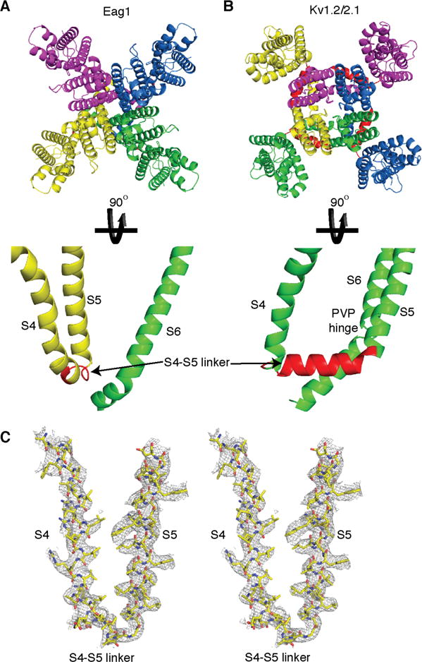
Architecture of transmembrane domains (S1–S6). The transmembrane segments (S1–S6) of rEag (A) and Kv1.2-2.1 (B) (PDB ID 2R9R) are shown with each subunit represented as a different color and the S4–S5 linker shown in red. (C) Stereoview of S4, the S4–S5 linker, and S5 segments of rEag1 (shown as sticks with yellow C, red O, and blue N) with EM density.
The third difference is the structure of the S4–S5 linker. In Eag1, the S4–S5 linker is a short 5-residue loop (Fig. 3A, 4A, C, S6). In Kv1.2–2.1, the S4–S5 linker is a 15-residue helix that runs parallel to the membrane (Fig. 3B, 4B). This change in the length and structure of the S4–S5 linker has important implications in the architecture of S1–S6 and channel gating.
Architecture of S1–S6
The 15-residue helical S4–S5 linker in Kv1.2–2.1 structure results in domain swapped transmembrane segments (VS interacts with the S5 from a neighboring subunit) (Fig. 4B) (1, 2). This domain swap positions the S4–S5 linker of Kv1.2–2.1 above S6 from within its own subunit and creates a ring of S4–S5 linker helices that wrap around the S6 helices (1, 2). The 5-residue S4–S5 linker of Eag1 cannot span the ~20 Å distance between S4 and S5 of the domain swapped Kv1.2–2.1. As a result, the transmembrane segments of Eag1 are not domain swapped (VS interacts with the S5 from the same subunit) and likely remain in a non-domain swapped conformation in all channel states (Fig. 4A, C). In the non-domain swapped architecture of Eag1, the S4–S5 linker is positioned above the S6 from the neighboring subunit and the interaction of S1 and S5 comprises the largest interface between the VS and pore (Fig. 4A, S8).
In Kv1.2–2.1, the position and structure of the S4–S5 linker as well as mutational studies on the closely-related Shaker Kv channel suggest that the S4–S5 linker functions as a mechanical lever to couple movement of the VS to S6 (Fig. 4B) (5, 38). A conserved proline in S6 was proposed to act as a hinge (Pro-Val-Pro hinge), allowing S6 to move up and down in the membrane in response to movement of the S4–S5 linker to open and close the channel (5, 39). However, the Eag1 S4–S5 linker is a short loop that is not domain swapped and, thus, is not in a position to function as a mechanical lever. Indeed, cutting the S4–S5 linker in Eag1, that is, deleting the covalent link between VS and pore, produces a functional voltage-gated channel (40). Furthermore, the S6 hinge proline is replaced by G469 in Eag1 (Fig. S6), which mutational experiments suggest does not function as a hinge (41). In agreement, S6 of Eag1 is entirely helical with no noticeable kinks before the S6 bundle crossing (Fig. 4A). These structural differences suggest that the mechanism of coupling VS movement to pore opening and closing is fundamentally different between Eag1 and Kv1.2–2.1. Sequence analysis indicates that all Eag family members have a short S4–S5 linker and no hinge proline in S6 while Kvs 1–9 have a longer S4–S5 linker and a hinge proline (Fig. 3, 4, S6). Therefore, we predict that all Eag family members will have a non-domain swapped architecture and gating mechanism similar to Eag1, and Kvs 1–9 will have a domain swapped architecture and gating mechanism similar to Kv1.2–2.1. Why is the mechanism of coupling VS movement to pore opening and closing different between the Eag family and Kvs 1–9 and how is movement of the VS coupled to the pore in Eag1? To answer these questions, it is necessary to first understand the mechanism of CaM inhibition and the interaction between the intracellular domains and the VS.
Mechanism of CaM inhibition
CaM binds Eag1 in the presence of Ca2+ and inhibits ion conduction (Fig. 1D) (18, 19). In agreement with this, when bound to CaM the rEag1 pore is closed with a diameter (~1 Å between van der Waal surfaces) less than that of hydrated potassium (6 – 8 Å) (Fig. 5A). In this closed conformation, the S6 of rEag1 has an approximately 55° bend directly after the inner helix gate (Q476) in a direction that would tighten the S6 helical bundle (Fig. 5B).
Fig. 5.

Intracellular domains and CaM interaction. (A) Two subunits of the tetramer are shown and sticks (green C, red O, and blue N) indicate the selectivity filter (436–441), constriction sites (F468, T472), and the bundle crossing (Q476) (left). The plot of pore diameter (right) is aligned with the molecular model. At all points the pore diameter is smaller than that of hydrated potassium (dashed grey line at 6Å). (B) Organization of rEag1 intracellular domains (extracellular view). Directly C-terminal to the bundle crossing (spheres colored as in A) the S6 helix (green) is connected to the C-linker (red). The CaM (purple) is bound to both the CNBHD (cyan) and the PAS (orange). (C) Two helices (683–695 and 708–722) at the C-terminus of the CNBHD (cyan, a dashed line shows the connection between helices) act as a claw to grab the CaM C-lobe (purple). The N-lobe of the same CaM molecule binds to a helix on the PAS domain (147–157, orange) that interacts with the neighboring CNBHD (grey). (D) The pore is closed with a 55° bend in S6 in a direction that tightens the helical bundle that forms the intracellular gate (Q476, spheres colored as in A). The VS (yellow) is in an up or depolarized conformation with the S4 directed towards the C-linker at a distance of 8 Å. The N-terminus of the PAS domain (orange sphere) and the S2–S3 linker are directed towards the interface between VS and C-linker.
Each Eag1 subunit has 3 CaM contact regions which form 2 binding sites (19). In rEag1, all three regions are occupied by one CaM molecule and thus 4 CaM molecules are bound to the rEag1 tetramer (Fig. 5B, C). The two contact regions at the C-terminus of the CNBHD form 2 α-helices that act as a claw to grab the CaM C-lobe. The first helix (residues 683-695), which has been shown to bind with lower affinity, interacts with the top of the CaM C-lobe near the Ca2+ binding sites and the second helix (residues 708–722), which has been shown to bind with higher affinity, is bound to the hydrophobic pocket of the CaM C-lobe (Fig. 5B, C and S9) (19). The linker helix in CaM that connects the C- and N-lobes breaks, forming a loop from M76-D80, a segment of high flexibility in CaM (Fig. S9) (42). The break in the linker helix allows the hydrophobic core of the CaM N-lobe to bind a helix (residues 147–157) on the PAS domain (Fig. 5B, C, S9). Importantly, this PAS domain interacts with the neighboring CNBHD. We propose the modeled orientation of the CaM lobes for two reasons. First, the linker constraints will only allow for this orientation (Fig. S9). Second, further classification of the rEag1 particles generated a cryo-EM density map with improved CaM density that shows the position of the linker connecting the CaM lobes (Fig. S9).
By binding to the CNBHD and PAS from neighboring subunits, we propose that the CaM acts as a molecular clamp to pull the two domains together and thereby alter the orientation of neighboring CNBHD domains (cyan and grey in Fig. 5C). Such a clamping mechanism would translate the CNBHD interacting with the CaM (cyan in Fig. 5C) towards the neighboring PAS domain (Fig. 6A). Since the CNBHD domain is connected to S6 via the C-linker, the movement of the CNBHD towards the PAS domain would cause a rotation of both the C-linker and S6, which may induce the 55° bend in a direction that tightens the helical bundle that forms the intracellular gate and close the pore (Fig. 6A). Thus, CaM binding appears to twist the pore helices shut.
Fig. 6.
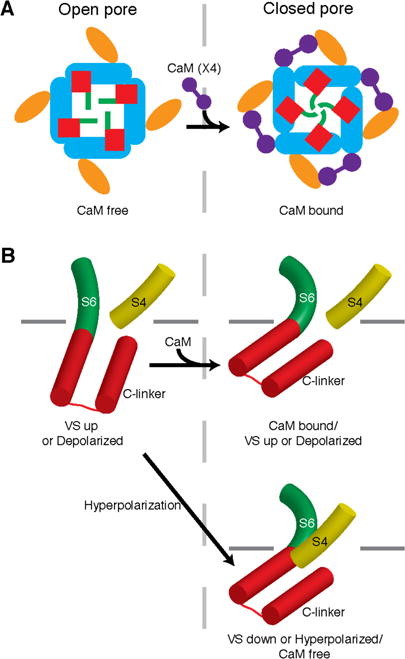
Proposed mechanism of CaM inhibition and voltage-dependent gating. (A) By binding to the PAS (orange) and CNBHD (cyan), the CaM (purple) molecule seems to pull the CNBHD, which is connected to the S6 (green) via the C-linker (red), towards the PAS domain. This would cause a clockwise rotation (when viewed from the extracellular side of the membrane) of the Clinker and S6 to close the potassium pore. (B) In the structure of rEag1 bound to CaM, the pore is closed with a 55° bend in S6 (green cylinder) in a direction that tightens the helical bundle that forms the intracellular gate, but the VS is in an up or depolarized conformation with the S4 (yellow cylinder) directed towards the C-linker (red cylinders) at a distance of 8 Å (top right, same conformation as Fig. 5D). In an up or depolarized state of the VS in the absence of CaM, the C-linker might rotate in a direction that loosens the helical bundle to relieve the curve in S6 and open the channel (left). In the closed/hyperpolarized state of the VS, the downward movement of the S4 might contact the C-linker to induce a bend in S6 similar to that imposed by CaM binding to close the channel (bottom right panel). Inner leaflet of the membrane is indicated by grey lines.
Insights into voltage-dependent gating
Functionally, CaM binding induces pore closure independent of voltage (Fig. 1D) (18, 19). The basis for this effect is observed in the structure of Eag1 bound to CaM as the closed pore is decoupled from the up or depolarized VS (Fig. 3A, 5D). The non-domain swapped architecture of the Eag1 S1–S6, in which the S4–S5 linker is a short loop that forms a weak interaction with S6 from the neighboring subunit (Fig. 4A) rather than a helix that wraps around the S6 helices as in Kv1.2–2.1 (Fig. 4B), allows for pore closure by cytoplasmic domains independent of VS conformation. In this closed conformation, the C-terminus of S4 is directed towards the C-linker at a distance of ~8Å (Fig. 5D). We hypothesize that upon release of CaM, the C-linker and S6 would rotate towards the S4 in a direction that loosens the helical bundle. Such a rotation would relieve the high energy 55° bend in S6 and open the channel (Fig. 6B).
In the up or depolarized conformation of the VS, the S4–S5 linker interacts with the intracellular portion of S6 and thereby directs the C-terminus of S4 towards the C-linker (Fig. 5D). In a down or hyperpolarized conformation of the VS, we hypothesize that the C-terminus of S4 will move towards the cytoplasm to interact with the C-linker and induce a bend in S6 similar to that imposed by CaM binding to close the channel (Fig. 6B). This mechanism, in which S4, rather than the S4–S5 linker, directly interacts with the C-linker to close the channel, would not require a covalent link between S4 and S5 to produce a voltage-dependent channel and thus is consistent with previous reports (40). The N-terminus of the PAS domain extends from the helical PAS cap (residues 17 to 25) and is directed towards the interface between S4 and C-linker through interactions with the PAS C-terminal loop, the S2–S3 linker, and the CNBHD (Fig. 5D, S7). In this position, the N-terminus of the PAS domain may interact with the VS in a down or hyperpolarized conformation to stabilize the closed state and confer activation time sensitivity to hyperpolarization (8). The S2–S3 linker is also directed towards the S4/C-linker interface and may play a yet unknown role in channel gating.
Summary
The structure of rEag1 reveals a non-domain swapped architecture of the S1–S6, which is due to a short 5-residue S4–S5 linker. This represents a divergence from the domain swapped architecture of previous voltage-gated ion channel structures (Fig. 4) (1–4) and suggests a new paradigm for voltage-dependent gating for the Eag family of Kv channels. Based on the structure of Eag1, we propose a gating mechanism in which S4 enters the cytoplasm in a down or hyperpolarized state to interact with and induce a rotation of the C-linker and S6 in a direction that tightens the helical bundle to close the channel (Fig. 6B). In the up or depolarized state of the VS, S4 moves into the membrane, allowing the C-linker and S6 to rotate in a direction that loosens the helical bundle and thus relieves the high energy bend in S6 to open the channel (Fig. 6B).
Two important consequences result from a gating mechanism in which the VS interacts with the cytoplasmic domains to gate the channel. First, this allows the cytoplasmic domains to close the channel independent of VS conformation. This is observed in the structure of Eag1 as binding of CaM to the cytoplasmic domains closes the pore but the VS is in the up or depolarized conformation. Second, this provides an added level of regulation through the interaction of intracellular domains with the voltage-dependent gating machinery. In Eag1, the N-terminus of the PAS domain, which confers sensitivity to hyperpolarization (8), is poised to interact with the S4 and S4–S5 linker in a closed conformation (Fig. 5D).
Supplementary Material
Summary.
Structure of a voltage-gated potassium channel reveals mechanism of interplay between voltage-dependent and ligand gating.
Acknowledgments
We thank M. Ebrahim at the Rockefeller University Cryo-EM resource center for help with data collection and J. Chen and members of the MacKinnon laboratory for helpful discussions. This work was supported in part by National Institutes of Health grant GM43949. J.R.W. is a Damon Runyon Fellow supported by the Damon Runyon Cancer Research Foundation (DRG-2212-15) and R.M. is an investigator in the Howard Hughes Medical Institute.
Footnotes
The low pass filtered and amplitude modified 3D cryo-EM density maps for rEag1 have been deposited in the electron microscopy data bank with accession code EMD-8215. Atomic coordinates for rEag1 have been deposited in the protein data bank under accession code 5K7L.
J.R.W. performed functional experiments and expressed, purified, and determined single particle cryo-EM structure of rEag1. J.R.W. and R.M. designed experiments, analyzed and interpreted results, and wrote the manuscript.
References and notes
- 1.Long SB, Campbell EB, Mackinnon R. Crystal structure of a mammalian voltage-dependent Shaker family K+ channel. Science. 2005;309:897–903. doi: 10.1126/science.1116269. [DOI] [PubMed] [Google Scholar]
- 2.Long SB, Tao X, Campbell EB, MacKinnon R. Atomic structure of a voltage-dependent K+ channel in a lipid membrane-like environment. Nature. 2007;450:376–382. doi: 10.1038/nature06265. [DOI] [PubMed] [Google Scholar]
- 3.Payandeh J, Scheuer T, Zheng N, Catterall WA. The crystal structure of a voltage-gated sodium channel. Nature. 2011;475:353–358. doi: 10.1038/nature10238. [DOI] [PMC free article] [PubMed] [Google Scholar]
- 4.Wu J, et al. Structure of the voltage-gated calcium channel Cav1.1 complex. Science. 2015;350:aad2395. doi: 10.1126/science.aad2395. [DOI] [PubMed] [Google Scholar]
- 5.Long SB, Campbell EB, Mackinnon R. Voltage sensor of Kv1.2: structural basis of electromechanical coupling. Science. 2005;309:903–908. doi: 10.1126/science.1116270. [DOI] [PubMed] [Google Scholar]
- 6.Guy HR, Durell SR, Warmke J, Drysdale R, Ganetzky B. Similarities in amino acid sequences of Drosophila eag and cyclic nucleotide-gated channels. Science. 1991;254:730. doi: 10.1126/science.1658932. [DOI] [PubMed] [Google Scholar]
- 7.Ju M, Wray D. Molecular regions responsible for differences in activation between heag channels. Biochem Biophys Res Commun. 2006;342:1088–1097. doi: 10.1016/j.bbrc.2006.02.062. [DOI] [PubMed] [Google Scholar]
- 8.Terlau H, Heinemann SH, Stuhmer W, Pongs O, Ludwig J. Amino terminal-dependent gating of the potassium channel rat eag is compensated by a mutation in the S4 segment. J Physiol. 1997;502(Pt 3):537–543. doi: 10.1111/j.1469-7793.1997.537bj.x. [DOI] [PMC free article] [PubMed] [Google Scholar]
- 9.Cabral JH Morais, et al. Crystal structure and functional analysis of the HERG potassium channel N terminus: a eukaryotic PAS domain. Cell. 1998;95:649–655. doi: 10.1016/s0092-8674(00)81635-9. [DOI] [PubMed] [Google Scholar]
- 10.Muskett FW, et al. Mechanistic insight into human ether-a-go-go-related gene (hERG) K+ channel deactivation gating from the solution structure of the EAG domain. J Biol Chem. 2011;286:6184–6191. doi: 10.1074/jbc.M110.199364. [DOI] [PMC free article] [PubMed] [Google Scholar]
- 11.Wang J, Trudeau MC, Zappia AM, Robertson GA. Regulation of deactivation by an amino terminal domain in human ether-a-go-go-related gene potassium channels. J Gen Physiol. 1998;112:637–647. doi: 10.1085/jgp.112.5.637. [DOI] [PMC free article] [PubMed] [Google Scholar]
- 12.Zagotta WN, et al. Structural basis for modulation and agonist specificity of HCN pacemaker channels. Nature. 2003;425:200–205. doi: 10.1038/nature01922. [DOI] [PubMed] [Google Scholar]
- 13.Brelidze TI, Carlson AE, Zagotta WN. Absence of direct cyclic nucleotide modulation of mEAG1 and hERG1 channels revealed with fluorescence and electrophysiological methods. J Biol Chem. 2009;284:27989–27997. doi: 10.1074/jbc.M109.016337. [DOI] [PMC free article] [PubMed] [Google Scholar]
- 14.Brelidze TI, Carlson AE, Sankaran B, Zagotta WN. Structure of the carboxy-terminal region of a KCNH channel. Nature. 2012;481:530–533. doi: 10.1038/nature10735. [DOI] [PMC free article] [PubMed] [Google Scholar]
- 15.Marques-Carvalho MJ, et al. Structural, biochemical, and functional characterization of the cyclic nucleotide binding homology domain from the mouse EAG1 potassium channel. J Mol Biol. 2012;423:34–46. doi: 10.1016/j.jmb.2012.06.025. [DOI] [PubMed] [Google Scholar]
- 16.Haitin Y, Carlson AE, Zagotta WN. The structural mechanism of KCNH-channel regulation by the eag domain. Nature. 2013;501:444–448. doi: 10.1038/nature12487. [DOI] [PMC free article] [PubMed] [Google Scholar]
- 17.Ludwig J, et al. Functional expression of a rat homologue of the voltage gated either a go-go potassium channel reveals differences in selectivity and activation kinetics between the Drosophila channel and its mammalian counterpart. EMBO J. 1994;13:4451–4458. doi: 10.1002/j.1460-2075.1994.tb06767.x. [DOI] [PMC free article] [PubMed] [Google Scholar]
- 18.Schonherr R, Lober K, Heinemann SH. Inhibition of human ether a go-go potassium channels by Ca(2+)/calmodulin. EMBO J. 2000;19:3263–3271. doi: 10.1093/emboj/19.13.3263. [DOI] [PMC free article] [PubMed] [Google Scholar]
- 19.Ziechner U, et al. Inhibition of human ether a go-go potassium channels by Ca2+/calmodulin binding to the cytosolic N- and C-termini. FEBS J. 2006;273:1074–1086. doi: 10.1111/j.1742-4658.2006.05134.x. [DOI] [PubMed] [Google Scholar]
- 20.Mortensen LS, et al. KV10.1 opposes activity-dependent increase in Ca2+ influx into the presynaptic terminal of the parallel fibre - Purkinje cell synapse. J Physiol. 2014 doi: 10.1113/jphysiol.2014.281600. [DOI] [PMC free article] [PubMed] [Google Scholar]
- 21.Bijlenga P, et al. An ether -a-go-go K+ current, Ih-eag, contributes to the hyperpolarization of human fusion-competent myoblasts. J Physiol. 1998;512(Pt 2):317–323. doi: 10.1111/j.1469-7793.1998.317be.x. [DOI] [PMC free article] [PubMed] [Google Scholar]
- 22.Pardo LA, Bruggemann A, Camacho J, Stuhmer W. Cell cycle-related changes in the conducting properties of r-eag K+ channels. J Cell Biol. 1998;143:767–775. doi: 10.1083/jcb.143.3.767. [DOI] [PMC free article] [PubMed] [Google Scholar]
- 23.Pardo LA, et al. Oncogenic potential of EAG K(+) channels. EMBO J. 1999;18:5540–5547. doi: 10.1093/emboj/18.20.5540. [DOI] [PMC free article] [PubMed] [Google Scholar]
- 24.Hemmerlein B, et al. Overexpression of Eag1 potassium channels in clinical tumours. Mol Cancer. 2006;5(41) doi: 10.1186/1476-4598-5-41. [DOI] [PMC free article] [PubMed] [Google Scholar]
- 25.Agarwal JR, Griesinger F, Stuhmer W, Pardo LA. The potassium channel Ether a go-go is a novel prognostic factor with functional relevance in acute myeloid leukemia. Mol Cancer. 2010;9(18) doi: 10.1186/1476-4598-9-18. [DOI] [PMC free article] [PubMed] [Google Scholar]
- 26.Mello de Queiroz F, Suarez-Kurtz G, Stuhmer W, Pardo LA. Ether a go-go potassium channel expression in soft tissue sarcoma patients. Mol Cancer. 2006;5(42) doi: 10.1186/1476-4598-5-42. [DOI] [PMC free article] [PubMed] [Google Scholar]
- 27.Downie BR, et al. Eag1 expression interferes with hypoxia homeostasis and induces angiogenesis in tumors. J Biol Chem. 2008;283:36234–36240. doi: 10.1074/jbc.M801830200. [DOI] [PMC free article] [PubMed] [Google Scholar]
- 28.Gomez-Varela D, et al. Monoclonal antibody blockade of the human Eag1 potassium channel function exerts antitumor activity. Cancer Res. 2007;67:7343–7349. doi: 10.1158/0008-5472.CAN-07-0107. [DOI] [PubMed] [Google Scholar]
- 29.Garcia-Quiroz J, et al. Astemizole synergizes calcitriol antiproliferative activity by inhibiting CYP24A1 and upregulating VDR: a novel approach for breast cancer therapy. PLoS One. 2012;7:e45063. doi: 10.1371/journal.pone.0045063. [DOI] [PMC free article] [PubMed] [Google Scholar]
- 30.Ludwig J, Owen D, Pongs O. Carboxy-terminal domain mediates assembly of the voltage-gated rat ether-a-go-go potassium channel. EMBO J. 1997;16:6337–6345. doi: 10.1093/emboj/16.21.6337. [DOI] [PMC free article] [PubMed] [Google Scholar]
- 31.Ju M, Wray D. Molecular identification and characterisation of the human eag2 potassium channel. FEBS Lett. 2002;524:204–210. doi: 10.1016/s0014-5793(02)03055-7. [DOI] [PubMed] [Google Scholar]
- 32.Jiang Y, et al. X-ray structure of a voltage-dependent K+ channel. Nature. 2003;423:33–41. doi: 10.1038/nature01580. [DOI] [PubMed] [Google Scholar]
- 33.Hsu PH, et al. 14-3-3theta is a binding partner of rat Eag1 potassium channels. PLoS One. 2012;7:e41203. doi: 10.1371/journal.pone.0041203. [DOI] [PMC free article] [PubMed] [Google Scholar]
- 34.Tao X, Lee A, Limapichat W, Dougherty DA, MacKinnon R. A gating charge transfer center in voltage sensors. Science. 2010;328:67–73. doi: 10.1126/science.1185954. [DOI] [PMC free article] [PubMed] [Google Scholar]
- 35.Zhang M, Liu J, Tseng GN. Gating charges in the activation and inactivation processes of the HERG channel. J Gen Physiol. 2004;124:703–718. doi: 10.1085/jgp.200409119. [DOI] [PMC free article] [PubMed] [Google Scholar]
- 36.Aggarwal SK, MacKinnon R. Contribution of the S4 segment to gating charge in the Shaker K+ channel. Neuron. 1996;16:1169–1177. doi: 10.1016/s0896-6273(00)80143-9. [DOI] [PubMed] [Google Scholar]
- 37.Seoh SA, Sigg D, Papazian DM, Bezanilla F. Voltage-sensing residues in the S2 and S4 segments of the Shaker K+ channel. Neuron. 1996;16:1159–1167. doi: 10.1016/s0896-6273(00)80142-7. [DOI] [PubMed] [Google Scholar]
- 38.Lu Z, Klem AM, Ramu Y. Ion conduction pore is conserved among potassium channels. Nature. 2001;413:809–813. doi: 10.1038/35101535. [DOI] [PubMed] [Google Scholar]
- 39.del Camino D, Holmgren M, Liu Y, Yellen G. Blocker protection in the pore of a voltage-gated K+ channel and its structural implications. Nature. 2000;403:321–325. doi: 10.1038/35002099. [DOI] [PubMed] [Google Scholar]
- 40.Lorinczi E, et al. Voltage-dependent gating of KCNH potassium channels lacking a covalent link between voltage-sensing and pore domains. Nat Commun. 2015;6:6672. doi: 10.1038/ncomms7672. [DOI] [PMC free article] [PubMed] [Google Scholar]
- 41.Hardman RM, Stansfeld PJ, Dalibalta S, Sutcliffe MJ, Mitcheson JS. Activation gating of hERG potassium channels: S6 glycines are not required as gating hinges. J Biol Chem. 2007;282:31972–31981. doi: 10.1074/jbc.M705835200. [DOI] [PubMed] [Google Scholar]
- 42.Barbato G, Ikura M, Kay LE, Pastor RW, Bax A. Backbone dynamics of calmodulin studied by 15N relaxation using inverse detected two-dimensional NMR spectroscopy: the central helix is flexible. Biochemistry. 1992;31:5269–5278. doi: 10.1021/bi00138a005. [DOI] [PubMed] [Google Scholar]
- 43.Goehring A, et al. Screening and large-scale expression of membrane proteins in mammalian cells for structural studies. Nat Protoc. 2014;9:2574–2585. doi: 10.1038/nprot.2014.173. [DOI] [PMC free article] [PubMed] [Google Scholar]
- 44.Kirchhofer A, et al. Modulation of protein properties in living cells using nanobodies. Nat Struct Mol Biol. 2010;17:133–138. doi: 10.1038/nsmb.1727. [DOI] [PubMed] [Google Scholar]
- 45.Mastronarde DN. Automated electron microscope tomography using robust prediction of specimen movements. J Struct Biol. 2005;152:36–51. doi: 10.1016/j.jsb.2005.07.007. [DOI] [PubMed] [Google Scholar]
- 46.Grant T, Grigorieff N. Measuring the optimal exposure for single particle cryo-EM using a 2.6 A reconstruction of rotavirus VP6. Elife. 2015;4:e06980. doi: 10.7554/eLife.06980. [DOI] [PMC free article] [PubMed] [Google Scholar]
- 47.Rohou A, Grigorieff N. CTFFIND4: Fast and accurate defocus estimation from electron micrographs. J Struct Biol. 2015;192:216–221. doi: 10.1016/j.jsb.2015.08.008. [DOI] [PMC free article] [PubMed] [Google Scholar]
- 48.Scheres SH. A Bayesian view on cryo-EM structure determination. J Mol Biol. 2012;415:406–418. doi: 10.1016/j.jmb.2011.11.010. [DOI] [PMC free article] [PubMed] [Google Scholar]
- 49.Tang G, et al. EMAN2: an extensible image processing suite for electron microscopy. J Struct Biol. 2007;157:38–46. doi: 10.1016/j.jsb.2006.05.009. [DOI] [PubMed] [Google Scholar]
- 50.Lyumkis D, Brilot AF, Theobald DL, Grigorieff N. Likelihood-based classification of cryo-EM images using FREALIGN. J Struct Biol. 2013;183:377–388. doi: 10.1016/j.jsb.2013.07.005. [DOI] [PMC free article] [PubMed] [Google Scholar]
- 51.Rosenthal PB, Henderson R. Optimal determination of particle orientation, absolute hand, and contrast loss in single-particle electron cryomicroscopy. J Mol Biol. 2003;333:721–745. doi: 10.1016/j.jmb.2003.07.013. [DOI] [PubMed] [Google Scholar]
- 52.Emsley P, Lohkamp B, Scott WG, Cowtan K. Features and development of Coot. Acta Crystallogr D Biol Crystallogr. 2010;66:486–501. doi: 10.1107/S0907444910007493. [DOI] [PMC free article] [PubMed] [Google Scholar]
- 53.Chattopadhyaya R, Meador WE, Means AR, Quiocho FA. Calmodulin structure refined at 1.7 A resolution. J Mol Biol. 1992;228:1177–1192. doi: 10.1016/0022-2836(92)90324-d. [DOI] [PubMed] [Google Scholar]
- 54.Winn MD, et al. Overview of the CCP4 suite and current developments. Acta Crystallogr D Biol Crystallogr. 2011;67:235–242. doi: 10.1107/S0907444910045749. [DOI] [PMC free article] [PubMed] [Google Scholar]
- 55.Adams PD, et al. PHENIX: a comprehensive Python-based system for macromolecular structure solution. Acta Crystallogr D Biol Crystallogr. 2010;66:213–221. doi: 10.1107/S0907444909052925. [DOI] [PMC free article] [PubMed] [Google Scholar]
- 56.Brown A, et al. Tools for macromolecular model building and refinement into electron cryo-microscopy reconstructions. Acta Crystallogr D Biol Crystallogr. 2015;71:136–153. doi: 10.1107/S1399004714021683. [DOI] [PMC free article] [PubMed] [Google Scholar]
- 57.Murshudov GN, Vagin AA, Dodson EJ. Refinement of macromolecular structures by the maximum-likelihood method. Acta Crystallogr D Biol Crystallogr. 1997;53:240–255. doi: 10.1107/S0907444996012255. [DOI] [PubMed] [Google Scholar]
- 58.Nicholls RA, Fischer M, McNicholas S, Murshudov GN. Conformation-independent structural comparison of macromolecules with ProSMART. Acta Crystallogr D Biol Crystallogr. 2014;70:2487–2499. doi: 10.1107/S1399004714016241. [DOI] [PMC free article] [PubMed] [Google Scholar]
- 59.Pettersen EF, et al. UCSF Chimera—a visualization system for exploratory research and analysis. Journal of computational chemistry. 2004;25:1605–1612. doi: 10.1002/jcc.20084. [DOI] [PubMed] [Google Scholar]
- 60.Smart OS, Neduvelil JG, Wang X, Wallace BA, Sansom MS. HOLE: a program for the analysis of the pore dimensions of ion channel structural models. J Mol Graph. 1996;14:354–360. 376. doi: 10.1016/s0263-7855(97)00009-x. [DOI] [PubMed] [Google Scholar]
- 61.Dolinsky TJ, et al. PDB2PQR: expanding and upgrading automated preparation of biomolecular structures for molecular simulations. Nucleic Acids Res. 2007;35:W522–525. doi: 10.1093/nar/gkm276. [DOI] [PMC free article] [PubMed] [Google Scholar]
- 62.Baker NA, Sept D, Joseph S, Holst MJ, McCammon JA. Electrostatics of nanosystems: application to microtubules and the ribosome. Proc Natl Acad Sci U S A. 2001;98:10037–10041. doi: 10.1073/pnas.181342398. [DOI] [PMC free article] [PubMed] [Google Scholar]
- 63.Heymann JB, Belnap DM. Bsoft: image processing and molecular modeling for electron microscopy. J Struct Biol. 2007;157:3–18. doi: 10.1016/j.jsb.2006.06.006. [DOI] [PubMed] [Google Scholar]
- 64.Morin A, et al. Collaboration gets the most out of software. Elife. 2013;2:e01456. doi: 10.7554/eLife.01456. [DOI] [PMC free article] [PubMed] [Google Scholar]
Associated Data
This section collects any data citations, data availability statements, or supplementary materials included in this article.