

Abstract
Background
This study aimed to evaluate whether obliquely angled and ring-shaped titanium mesh cage (TMC) end structures can improve the compressive load on the endplate interface in anterior cervical corpectomy and fusion (ACCF).
Material/Methods
A total of 23 volunteers underwent cervical lateral x-ray. The oblique angle of the superior endplate was measured, which was used to construct the gradient of the TMC end. Forty-two fresh cadaveric vertebral bodies were harvested and randomly distributed among four TMC groups with different ends. The baseline indicators of bone mineral density and anteroposterior and transverse dimensions were recorded. The superior endplate was placed at an angle of 12° when performing uniaxial compression testing. The maximum loads of the four TMCs were assessed.
Results
There were no significant differences among the groups regarding the baseline indicators. The conventional TMC had the lowest maximum load (1362.3±221.78 N, p<0.05), whereas the TMC with an obliquely end ring had the highest maximum load (2095.82±285.64 N, p<0.05). The maximum loads of the TMCs with oblique footprints and flat end ring were much higher than that of the conventional TMC (p<0.05) but significantly lower than that of the TMC with the obliquely end ring (p<0.05), with average values of 1806.91±246.98 N and 1725.3±213.33 N, respectively.
Conclusions
Both the ring shape and oblique angle of the TMC end contributed to an increase in compressive force and are advocated for use in TMC structure optimization to decrease the incidence of TMC subsidence in ACCF.
MeSH Keywords: Cadaver; Compressive Strength; Decompression, Surgical; Prosthesis Design; Spinal FusionX
Background
Due to its advantages of a high fusion rate and the avoidance of donor site complications, the titanium mesh cage (TMC) is now widely used for intervertebral reconstruction in anterior cervical corpectomy and fusion (ACCF) [1–3]. However, clinical outcomes have shown a high rate of TMC subsidence during the follow-up period [4–11]. Severe TMC subsidence (>3 mm) has been reported in up to 30.8% of patients [4–7] and can lead to multiple complications, such as kyphosis, nerve recompression, and internal fixation failures, which undermine the surgical treatment [1,4,5,7,8,10,12–14].
Biomechanical studies have noted some factors that are closely associated with TMC subsidence, one of which is bone mineral density (BMD). As BMD decreases, the maximum load decreases, and the TMC becomes more likely to penetrate the vertebral body [15–19]. Another factor is the condition of the endplate. When the endplate is completely removed from the vertebral body, the maximum load can decrease by 38.9–67% compared with that of an intact vertebral body [15,19–22]. A third factor is TMC-endplate interface. A TMC with a larger diameter is recommended due to the advantages of relying on the strong posterolateral region of the endplate, a larger TMC-endplate interface contact area, and a larger bone graft volume [17,18,21,23]. In addition, adding an end ring onto the conventional TMC is considered effective for increasing the compressive load because it alleviates the stress concentration of the interface by evenly distributing the stress [16,21,24].
However, few studies have considered the effects of the included angle between the TMC and the endplate on the compressive load. Under physiological conditions, the cervical spine has a lordotic alignment, and the superior endplate has a corresponding gradient [4,5]. Following ACCF, a flat-ended TMC only contacts the superior endplate in the posterior region, which leads to a TMC-endplate interface with a very small contact area [4,5,9]. When the endplate is placed flat for testing [16,21,24], the contact area of the interface is artificially expanded, which might result in an exaggerated maximum load. Thus, it is imperative to place the endplate at a physiological gradient during compression testing to evaluate the true mechanical behavior of the TMC-endplate interface. In the present study, TMCs with different ends were constructed and tested under the true physiological condition. The respective and combined effects of the ring shape and oblique angle of the TMC end structures on the compressive force were assessed to provide evidence for optimization of the conventional TMC.
Material and Methods
This study was approved by the institutional review board of the Second Affiliated Hospital of Xi’an Jiaotong University. A total of 23 young, healthy volunteers (13 males and 10 females; age range, 18–27 years; mean age, 22.74±2.61 years) were enrolled. All volunteers underwent cervical lateral x-ray to measure the oblique angle of the superior endplate (C4–T1). To obtain the included angle between the superior endplate and the inferior end of the TMC following one-level (C3–C7) ACCF surgeries, the oblique angle was defined as the angle between the superior endplate of the targeted vertebral body and the inferior endplate of the next cephalad vertebral body (Figure 1). The average value of the oblique angle was used to construct the gradient of the TMC end and holding cup.
Figure 1.
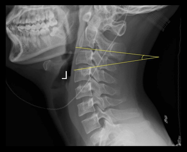
An illustrative case of the measurement of the C4 oblique angle. The C4 oblique angle was measured as the angle between the superior endplate of the C4 and the inferior endplate of the C2.
All the TMCs were constructed from a raw material of stainless steel powder using a selective laser melting 3D printing machine (BLT-S300, Bright Laser Technologies, Ltd., Xi’an, China). A total of four types of TMCs with different end configurations were designed (Figure 2A, 2B): 1) a conventional TMC; 2) a TMC with an oblique angle at 12°; 3) a TMC with a 0.95 cm2 end ring; and 4) a TMC with an oblique end ring (12° and 0.95 cm2). The diameter of all the TMCs was 1.4 cm. The bottom of the holding cup was also designed at an oblique angle of 12° (Figure 2C). Unlike the conventional cylindrical TMC, the TMC with an obliquely angled, ring-shaped end was designed to have a quadrate shape, which is shown in Figure 3.
Figure 2.

The structures of the TMCs and holding cup. (A, B) Four TMCs with different ends were constructed. From left to right, a conventional TMC, a TMC with an obliquely angled footprint, a TMC with a flat, ring-shaped end, and a TMC with obliquely angled, ring-shaped end. (C)The bottom of the holding cup has an oblique angle of 12°. (D) The superior endplate is placed parallel to the bottom of the holding cup.
Figure 3.
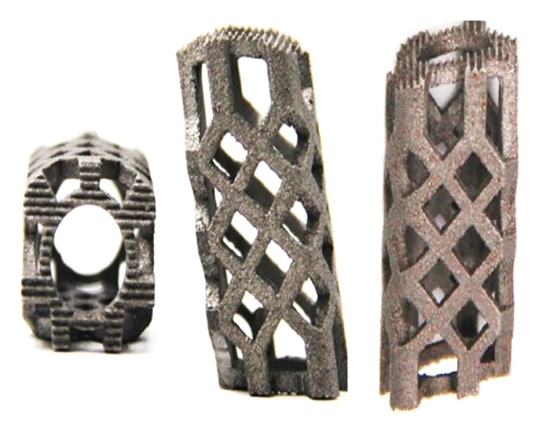
A quadrate-shaped TMC designed by the authors. The quadrate-shaped TMC has a fornixed end ring on the top and an end ring with a 12° oblique angle on the bottom to facilitate alignment with the endplate. The lateral sides of the quadrate-shaped TMC are flat, and the anterior and posterior sides of the TMC camber to the front.
A total of seven human cadaveric cervical spines were obtained from fresh cadavers (five males and two females; mean age, 66.71±13.71 years) and stored at −20°C until testing. The specimens were evaluated by x-ray to exclude vertebral deformities. A dual-energy radiograph absorptiometer (DEXA, Medix-90, Medilink, France) was used to measure the BMD of each vertebral body. During the test, the specimens were placed in a lateral position and embedded in a container filled with rice to simulate the soft tissues surrounding the cervical spine [17,25]. The BMD was measured with a region of interest, which reflected the whole vertebral body. After BMD testing, the specimens were dissected through the intervertebral disc and ligaments to obtain a separated vertebra. The annulus fibrosus tissue on the vertebra was carefully removed without damaging the endplate. The posterior elements of the vertebra were cut off through the pedicles using a bone saw, and all the soft tissue was removed. After processing, a total of 42 vertebral bodies were harvested. The anteroposterior and transverse dimensions of each superior endplate were recorded. The anteroposterior diameter was defined as the maximal distance from the mid-sagittal plane, and the transverse diameter was defined as the maximal distance from the mid-coronal plane. The 42 vertebral bodies were randomized among the four TMC groups. Each vertebral body was fixed in a holding cup using poly methyl methacrylate. The superior endplate was placed parallel to the bottom of the holding cup to simulate the physiological gradient of the superior endplate after one-level ACCF (Figure 2D).
Uniaxial compression testing was performed at the State Key Laboratory for Strength and Vibration of Mechanical Structures (Xi’an Jiaotong University, Xi’an, China). A computer-controlled servo hydraulic testing machine (858 Mini-Bionix Testing Machine, MTS Systems, Minneapolis, MN, USA) was used for all tests. Each TMC was carefully placed on the center of the vertebral body superior endplate (Figure 4). The compressive load was applied on the superior endplate with a displacement control of 10 mm/minute [15]. The maximum displacement of the TMC was 5 mm, which is sufficiently large to ensure destruction of the vertebral body. The compressive load and displacement data were collected at 600 Hz throughout the uniaxial compression testing. The maximum load was defined as the maximum force on each load-displacement curve.
Figure 4.

Four TMCs were placed on the center of the endplate and used for uniaxial compression testing. (A) Conventional TMC. (B) TMC with a flat, ring-shaped end. (C) TMC with an oblique footprint. (D) TMC with an obliquely angled, ring-shaped end.
All the measurement data are presented as the mean±standard deviation (SD). SPSS 18.0 was used for the statistical analysis. One-way ANOVA was applied to compare the oblique angle, BMD, anteroposterior dimension, transverse dimension, and maximum load among the groups. The LSD t-test was further applied as a post hoc test. For all statistical tests, a p value of less than 0.05 was considered statistically significant.
Results
The oblique endplate angle was used to simulate the angle between the flat TMC end and the superior endplate in one-level ACCF. The average oblique angles of C4-T1 are shown in Table 1. The oblique angle of T1 was significantly higher than that of the other segments (p<0.05). The average BMD and anteroposterior and transverse dimensions of each group are shown in Table 2. There were no significant differences among the groups in terms of the BMD or anteroposterior and transverse dimensions (p>0.05), which identified the comparability of the vertebral bodies among the groups.
Table 1.
The average oblique angle of each superior endplate.
| C4 | C5 | C6 | C7 | T1* | Total | |
|---|---|---|---|---|---|---|
| Mean (°) | 12.22 | 11.22 | 11.52 | 13.11 | 14.45 | 12.40 |
| SD | 3.03 | 2.65 | 2.61 | 3.51 | 2.15 | 3.02 |
The oblique angle of T1 is significantly greater than that of the other segments.
Table 2.
The BMD and anteroposterior and transverse dimensions for each TMC group.
| Conventional | Oblique footprint | Flat end ring | Oblique end ring | |
|---|---|---|---|---|
| BMD (mg/mm3) | 704±134 | 715±119 | 689±143 | 702±125 |
| Anteroposterior dimension (cm) | 1.62±0.16 | 1.63±0.16 | 1.66±0.15 | 1.58±0.15 |
| Transverse dimension (cm) | 1.91±0.32 | 1.95±0.34 | 1.84±0.32 | 1.85±0.30 |
No significance differences were found among the groups.
The average maximum load of the conventional TMC was 1362.3±221.78 N, which was significantly lower than that of the other TMCs (p<0.05). The TMC with an oblique end ring showed the highest maximum load compared with the other TMCs, with an average value of 2095.82±285.64 N (p<0.05). The maximum loads of the oblique footprints and the flat end ring were much higher than that of the conventional TMC (p<0.05) but significantly lower than that of the TMC with oblique end ring (p<0.05), with average values of 1806.91±246.98 N and 1725.3±213.33 N, respectively (Figure 5). Representative load-displacement curves for each TMC type are shown in Figure 6.
Figure 5.
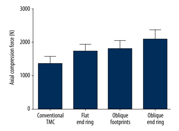
Comparison of the MCF among the groups.
Figure 6.
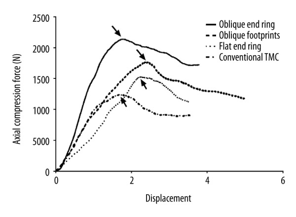
Representative load-displacement curve for each TMC.
Discussion
In the present study, the compressive testing results show that the maximum load of the conventional TMC is the lowest among the four TMC types. Adding an end ring or an oblique angle to the TMC end can significantly improve the maximum load by approximately 26.7% and 32.6%, respectively. Furthermore, when the TMC has both a ring-shaped end and an oblique angle, the maximum load can increase as much as 53.8%, providing the highest compressive force to resist subsidence.
Due to the advantages of lordosis reconstruction, intervertebral height restoration and sufficient decompression at both the vertebral body and disc levels, ACCF is widely used in the treatment of cervical diseases, such as spondylotic myelopathy, posterior longitudinal ligament ossification, cervical tuberculosis, and tumors [1,12,26]. In recent decades, the TMC has been widely used in this procedure because it can achieve satisfactory bony fusion and avoid donor site complications, such as blood loss, hematoma, infection, and pain. However, recent studies have reported high rates of TMC subsidence during follow-up of up to 93.3% [4–11]. Severe TMC subsidence (>3 mm) can result in multiple complications. First, the cervical curvature can change significantly due to severe subsidence and lead to kyphosis [1,12]. Second, the intervertebral foramen and the ligaments can shrink again, thereby inducing a recurrence of the neurological deterioration [4,5]. Third, severe subsidence increases the stress load on the plate and screws, which can result in internal fixation failures, such as breakage and extrusion [5,7,8,10,13,14].
Following ACCF, most TMC subsidence occurs in the posterior region of the caudal vertebral body [9] because the TMC is often placed on the anterior two-thirds of the endplate [9]. This placement causes the posterior end of the TMC to rely on the central portion of the endplate, which exhibits the lowest mechanical strength of the endplate [17,18,21,23]. TMC subsidence also occurs in this region because the superior endplate is oblique, and the flat end of the conventional TMC can only contact the posterior area of the endplate, which results in a very small contact area and a large stress concentration in this region (Figure 3A, 3B) [4,5,9,27]. Moreover, during surgery, the conventional TMC is usually manually clipped into a suitable size, which leaves very sharp edges on the TMC end and further decreases the contact area between the endplate and the TMC [4,5,11].
Biomechanical studies have shown that adding an end ring onto the conventional TMC could be beneficial by expanding the contact area between the endplate and the TMC, which can decrease the stress concentration and distribute the load from the cephalad more evenly across the endplate [16,21,24]. However, high rates of TMC subsidence were still observed in long-term follow-up studies of ACCF despite the enlarged contact area of the end surface [4,28,29], suggesting that a simple, flat end ring could not effectively prevent subsidence. When performing compression tests, previous biomechanical works assumed that the endplate was parallel to the end of the TMC and did not consider that the endplate has a gradient under physiological conditions [16,21,24]. Therefore, these studies may artificially increase the true contact area and exaggerate the effect of a flat end ring on the compressive load.
In the present study, the compression tests were performed by placing the vertebral bodies at a certain angle, which was identified by measuring the radiological cervical images of 23 young volunteers, to simulate the actual positional relationship between the TMC and the endplate following one-level ACCF. During the testing, an obvious gap could be observed between the conventional TMC and the anterior part of the endplate. In contrast, the TMC with an obliquely angled end was parallel to the endplate, which significantly increased the contact area between the TMC and the endplate. Compared with the conventional flat end, the obliquely angled end achieved a significantly greater maximum load, which suggested the importance of the geometrical match between the TMC and the endplate in preventing subsidence.
The results also showed that adding a flat end ring alone could increase the maximum load as well. Although the flat end ring did not fit well to the oblique endplate, it still showed some advantages in preventing subsidence. First, compared with the sharp footprint of the conventional TMC, the end ring could offer more contact area with the posterior part of the endplate and relieve the concentrated stress. In addition, as the end ring subsided into the vertebral body, the contact area with the cancellous bone expanded. However, the cancellous bone only contributed to 33–66.1% of the resistance to the axial load [15,19–22]; thus, the expanded contact area helped to resist TMC subsidence to some extent.
Due to the advantages of the desirable geometrical fit with the endplate and the increase in contact area, the TMC with an oblique end ring yielded the largest compressive force. Unlike the flat ring-shaped end, which initially only had a small contact area with the endplate and showed a gradually increased contact area with the cancellous bone during subsidence, the obliquely angled, ring-shaped end exhibited an initially maximized contact area [5,27]. This configuration effectively decreased the concentrated stress and ensured that the stress from the cephalad was evenly distributed across the endplate. Currently, multiple types of cages with large contact areas are used in ACCF. Yang et al. [30] designed a new 3D-printed, porous cage and used it for ACCF in a sheep model. Both ends of the cage showed full contact. Additionally, the gradient of the cage end was customized for each sheep, which ensured that both ends were aligned with the endplates and yielded the maximum contact area. Due to these advantageous design attributes, the radiological images at the last follow-up showed that no subsidence had occurred [30]. Zhang et al. [31,32] constructed a new nanohydroxyapatite/polyamide 66 (n-HA/PA66) cage, which had a wide annular rim of 3 mm and an obliquely angled end aligned with the endplate. These advantageous structures contributed to a significantly lower subsidence rate compared with that of the conventional TMC [32]. In addition, a new type of TMC designed by Yu et al. [7] incorporates an obliquely angled end ring, which ensures a large contact area at the TMC-endplate interface. Similarly, the radiological outcomes demonstrated the advantages of the obliquely angled end ring in preventing subsidence [7].
In ACCF, there is an opposing relation between the TMC-endplate contact area and bony fusion [25]. If the contact area is too large, the granulated cancellous bone in the TMC will have insufficient contact with the endplate, preventing bony fusion. Conversely, if the contact area is too small, the TMC can produce excessive stress concentrations on the endplate, which may result in subsidence [25]. A minimum contact area of 30% at the interface is considered to provide sufficiently high mechanical strength in the endplate, and similar compressive loads on the endplate have been observed compared with those of larger contact areas [25,33]. In the present study, the obliquely angled, ring-shaped end was designed to have an area of 0.95 mm2 and achieved approximately 31.5% surface coverage of the superior endplate (3.02 cm2), which ensured that the TMC-endplate interface provided sufficient mechanic strength and offer enough surface contact for bony fusion.
Unlike the conventional cylindrical TMC, the TMC with the obliquely angled, ring-shaped end was designed to have a quadrate shape (Figure 3). Compared with a cylindrical shape, the authors considered that a quadrate shape has some advantages, as follows. First, a quadrate TMC has more portions that contact the posterolateral regions of the endplate, which has much more mechanical strength than other parts of the endplate. Second, with equal diameters, the cross-sectional area of the quadrate shape is larger than that of the circle. Consequently, a quadrate-shaped TMC has a larger volume for bone grafting. Third, both sides of the quadrate-shaped TMC are flat, significantly increasing the contact area with the remaining vertebral body, which also facilitates bony fusion. Last, the posterior sides of the quadrate TMC camber to the front, leaving more space for the spinal cord and helping prevent nerve compression.
There are some limitations to the present study. First, the oblique angle data were obtained from young volunteers and did not include the data of older people. Thus, the average oblique angle may not reflect the status of the general population. Second, considering experimental cost and duration, we performed axial load compression testing to assess the compressive force of the TMCs. Unlike fatigue testing, which would have cyclically placed a physiological load on the endplate, the compression testing imposed a constantly increasing load or a displacement on the endplate, which may not simulate well the common clinical presentation of gradual subsidence. In addition, the outcomes of compression testing are affected by the loading conditions [15–23,25,33,34]. If the load increases rapidly, the maximum compressive force value is corresponding high. Conversely, the maximum compressive force becomes low when the load is set to increase slowly. Therefore, the outcomes of the compression testing can only be used for qualitative comparison among groups. In the future, a quantitative comparison reflecting the true mechanical strength of different TMC types should be performed via highly bionic fatigue testing.
Conclusions
The conventional TMC with a flat footprint showed the lowest compressive force at the TMC-endplate interface. In contrast, the TMC with an oblique end ring yielded the highest compressive force. Both the ring shape and the oblique angle of the TMC contributed to the increase in compressive force and are advocated for use in TMC structure optimization to decrease the incidence of TMC subsidence in ACCF.
Footnotes
Conflict of interests
None.
Source of support: This work was supported by the National Natural Science Foundation of China (81571209)
References
- 1.Dorai Z, Morgan H, Coimbra C. Titanium cage reconstruction after cervical corpectomy. J Neurosurg. 2003;99(1):3–7. doi: 10.3171/spi.2003.99.1.0003. [DOI] [PubMed] [Google Scholar]
- 2.Eck KR, Bridwell KH, Ungacta FF, et al. Analysis of titanium mesh cages in adults with minimum two-year follow-up. Spine. 2000;25(18):2407–15. doi: 10.1097/00007632-200009150-00023. [DOI] [PubMed] [Google Scholar]
- 3.Riew KD, Rhee JM. The use of titanium mesh cages in the cervical spine. Clin Orthop Relat Res. 2002;(394):47–54. doi: 10.1097/00003086-200201000-00006. [DOI] [PubMed] [Google Scholar]
- 4.Chen Y, Chen D, Guo Y, et al. Subsidence of titanium mesh cage: A study based on 300 cases. J Spinal Disord Tech. 2008;21(7):489–92. doi: 10.1097/BSD.0b013e318158de22. [DOI] [PubMed] [Google Scholar]
- 5.Wu JX, Luo D, Ye XJ, et al. Anatomy-related risk factors for the subsidence of titanium mesh cage in cervical reconstruction after one-level corpectomy. Int J Clin Exp Med. 2015;8(5):7405–11. [PMC free article] [PubMed] [Google Scholar]
- 6.Yan DL, Wang ZJ, Deng SJ, et al. Anterior corpectomy and reconstruction with titanium mesh cage and dynamic cervical plate for cervical spondylotic myelopathy in elderly osteoporosis patients. Arch Orthop Trauma Surg. 2011;131(10):1369–74. doi: 10.1007/s00402-011-1317-2. [DOI] [PubMed] [Google Scholar]
- 7.Fengbin Y, Jinhao M, Xinyuan L, et al. Evaluation of a new type of titanium mesh cage versus the traditional titanium mesh cage for single-level, anterior cervical corpectomy and fusion. Eur Spine J. 2013;22(12):2891–96. doi: 10.1007/s00586-013-2976-1. [DOI] [PMC free article] [PubMed] [Google Scholar]
- 8.Bilbao G, Duart M, Aurrecoechea JJ, et al. Surgical results and complications in a series of 71 consecutive cervical spondylotic corpectomies. Acta Neurochir (Wien) 2010;152(7):1155–63. doi: 10.1007/s00701-010-0660-3. [DOI] [PubMed] [Google Scholar]
- 9.Jang JW, Lee JK, Lee JH, et al. Effect of posterior subsidence on cervical alignment after anterior cervical corpectomy and reconstruction using titanium mesh cages in degenerative cervical disease. J Clin Neurosci. 2014;21(10):1779–85. doi: 10.1016/j.jocn.2014.02.016. [DOI] [PubMed] [Google Scholar]
- 10.Kanayama M, Hashimoto T, Shigenobu K, et al. Pitfalls of anterior cervical fusion using titanium mesh and local autograft. J Spinal Disord Tech. 2003;16(6):513–18. doi: 10.1097/00024720-200312000-00005. [DOI] [PubMed] [Google Scholar]
- 11.Yang X, Chen Q, Liu LM, et al. Comparison of anterior cervical fusion by titanium mesh cage versus nano-hydroxyapatite/polyamide cage following single-level corpectomy. Int Orthop. 2013;37(12):2421–27. doi: 10.1007/s00264-013-2101-4. [DOI] [PMC free article] [PubMed] [Google Scholar]
- 12.Andaluz N, Zuccarello M, Kuntz C. Long-term follow-up of cervical radiographic sagittal spinal alignment after 1-and 2-level cervical corpectomy for the treatment of spondylosis of the subaxial cervical spine causing radiculomyelopathy or myelopathy: A retrospective study Clinical article. J Neurosurg Spine. 2012;16(1):2–7. doi: 10.3171/2011.9.SPINE10430. [DOI] [PubMed] [Google Scholar]
- 13.Daubs MD. Early failures following cervical corpectomy reconstruction with titanium mesh cages and anterior plating. Spine. 2005;30(12):1402–6. doi: 10.1097/01.brs.0000166526.78058.3c. [DOI] [PubMed] [Google Scholar]
- 14.Xu H, Ren XF, Wang DW, et al. Clinical use of the nanohydroxyapatite/polyamide mesh cage in anterior cervical corpectomy and fusion surgery. Int Orthop. 2013;37(12):2421–27. doi: 10.1007/s00264-013-2101-4. [DOI] [PMC free article] [PubMed] [Google Scholar]
- 15.Lim TH, Kwon H, Jeon CH, et al. Effect of endplate conditions and bone mineral density on the compressive strength of the graft-endplate interface in anterior cervical spine fusion. Spine. 2001;26(8):951–56. doi: 10.1097/00007632-200104150-00021. [DOI] [PubMed] [Google Scholar]
- 16.Hasegawa K, Abe M, Washio T, et al. An experimental study on the interface strength between titanium mesh cage and vertebra in reference to vertebral bone mineral density. Spine. 2001;26(8):957–63. doi: 10.1097/00007632-200104150-00022. [DOI] [PubMed] [Google Scholar]
- 17.Grant JP, Oxland TR, Dvorak MF, et al. The effects of bone density and disc degeneration on the structural property distributions in the lower lumbar vertebral endplates. J Orthop Res. 2002;20(5):1115–20. doi: 10.1016/S0736-0266(02)00039-6. [DOI] [PubMed] [Google Scholar]
- 18.Ordway NR, Lu YM, Zhang X, et al. Correlation of cervical endplate strength with CT measured subchondral bone density. Eur Spine J. 2007;16(12):2104–9. doi: 10.1007/s00586-007-0482-z. [DOI] [PMC free article] [PubMed] [Google Scholar]
- 19.Truumees E, Demetropoulos CK, Yang KH, et al. Failure of human cervical endplates: A cadaveric experimental model. Spine. 2003;28(19):2204–8. doi: 10.1097/01.BRS.0000084881.11695.50. [DOI] [PubMed] [Google Scholar]
- 20.Oxland TR, Grant JP, Dvorak MF, et al. Effects of endplate removal on the structural properties of the lower lumbar vertebral bodies. Spine. 2003;28(8):771–77. [PubMed] [Google Scholar]
- 21.Lowe TG, Hashim S, Wilson LA, et al. A biomechanical study of regional endplate strength and cage morphology as it relates to structural interbody support. Spine. 2004;29(21):2389–94. doi: 10.1097/01.brs.0000143623.18098.e5. [DOI] [PubMed] [Google Scholar]
- 22.Cheng CC, Ordway NR, Zhang X, et al. Loss of cervical Endplate integrity following minimal surface preparation. Spine. 2007;32(17):1852–55. doi: 10.1097/BRS.0b013e31811ece5a. [DOI] [PubMed] [Google Scholar]
- 23.Polikeit A, Ferguson SJ, Nolte LP, et al. The importance of the endplate for interbody cages in the lumbar spine. Eur Spine J. 2003;12(6):556–61. doi: 10.1007/s00586-003-0556-5. [DOI] [PMC free article] [PubMed] [Google Scholar]
- 24.Ordway NR, Rim BC, Tan R, et al. Anterior cervical interbody constructs: Effect of a repetitive compressive force on the endplate. J Orthop Res. 2012;30(4):587–92. doi: 10.1002/jor.21566. [DOI] [PubMed] [Google Scholar]
- 25.Steffen T, Tsantrizos A, Aebi M. Effect of implant design and endplate preparation on the compressive strength of interbody fusion constructs. Spine. 2000;25(9):1077–84. doi: 10.1097/00007632-200005010-00007. [DOI] [PubMed] [Google Scholar]
- 26.Chen Z, Liu B, Dong J, et al. Comparison of anterior corpectomy and fusion versus laminoplasty for the treatment of cervical ossification of posterior longitudinal ligament: A meta-analysis. Neurosurg Focus. 2016;40(6):E8. doi: 10.3171/2016.3.FOCUS15596. [DOI] [PubMed] [Google Scholar]
- 27.Lou JG, Liu H, Rong X, et al. Geometry of inferior endplates of the cervical spine. Clin Neurol Neurosurg. 2016;142:132–36. doi: 10.1016/j.clineuro.2016.01.027. [DOI] [PubMed] [Google Scholar]
- 28.Lau D, Song YH, Guan Z, et al. Radiological outcomes of static vs. expandable titanium cages after corpectomy: A retrospective cohort analysis of subsidence. Neurosurgery. 2013;72(4):529–38. doi: 10.1227/NEU.0b013e318282a558. [DOI] [PubMed] [Google Scholar]
- 29.Woiciechowsky C. Distractable vertebral cages for reconstruction after cervical corpectomy. Spine. 2005;30(15):1736–41. doi: 10.1097/01.brs.0000172158.31437.ce. [DOI] [PubMed] [Google Scholar]
- 30.Yang J, Cai H, Lv J, et al. In vivo study of a self-stabilizing artificial vertebral body fabricated by electron beam melting. Spine (Phila Pa 1976) 2014;39(8):E486–92. doi: 10.1097/BRS.0000000000000211. [DOI] [PubMed] [Google Scholar]
- 31.Zhang Y, Deng X, Jiang D, et al. Long-term results of anterior cervical corpectomy and fusion with nano-hydroxyapatite/polyamide 66 strut for cervical spondylotic myelopathy. Sci Rep. 2016;6:26751. doi: 10.1038/srep26751. [DOI] [PMC free article] [PubMed] [Google Scholar]
- 32.Zhang Y, Quan Z, Zhao Z, et al. Evaluation of anterior cervical reconstruction with titanium mesh cages versus nano-hydroxyapatite/polyamide66 cages after 1- or 2-level corpectomy for multilevel cervical spondylotic myelopathy: A retrospective study of 117 patients. PLoS One. 2014;9(5):e96265. doi: 10.1371/journal.pone.0096265. [DOI] [PMC free article] [PubMed] [Google Scholar]
- 33.Closkey RF, Parsons JR, Lee CK, et al. Mechanics of interbody spinal-fusion – analysis of critical bone-graft area. Spine. 1993;18(8):1011–15. doi: 10.1097/00007632-199306150-00010. [DOI] [PubMed] [Google Scholar]
- 34.Hollowell JP, Vollmer DG, Wilson CR, et al. Biomechanical analysis of thoracolumbar interbody constructs – How important is the endplate? Spine. 1996;21(9):1032–36. doi: 10.1097/00007632-199605010-00007. [DOI] [PubMed] [Google Scholar]