Abstract
We calculate the optical attractive forces that occur between 30-nm Au or Ag nanocrystals when irradiated at visible wavelengths. These forces show resonances at dipolar plasmon wavelengths, similar to resonances in the near-field electromagnetic intensities. At MW/cm2 intensities, optical forces can be stronger than van der Waals forces and could be used to organize metallic particles. We also suggest that photonucleation of organic crystals from supersaturated liquid solutions may be caused by optical forces.
Keywords: nanoparticles, photonucleation, bispherical coordinates
This article investigates the possibility that optical forces might be used to organize metallic nanocrystals. It also considers whether optical forces might modify the precise geometry of junctions between metallic nanocrystals. Optical forces derive from the electromagnetic-field intensification that occurs near Ag and Au particles at certain resonance wavelengths. This effect is a local mode of the electromagnetic field: the dipolar surface plasmon. The particle acts as a microscopic antenna, increasing absorption and re-emission of light by nearby molecules and causing the surface-enhanced Raman effect (SERS) (1-5). This enhancement is especially interesting for two particles separated by just a few nanometers. The metallic electron excited-state polarization concentrates at the junction (6), producing a “hot spot” of enormous electromagnetic enhancement (7), sufficient to allow the observation of single-molecule Raman spectra (8-10).
This article considers the optical forces present between two such closely spaced r = 30-nm metallic particles. The internal electronic polarization in the metal that creates the enhanced local field in the junction also creates force between the particles. This force can be simply understood. Consider two identical particles (or molecules) separated by a distance z. In an electromagnetic field  , each particle will develop an ac dipole
  oscillating coherently with respect to
  . (In general, such electronic polarization optical dipoles P are the source of Rayleigh scattering, the optical Kerr effect, and trapping of single glass beads in focused laser beams.) Neglecting retardation, the two dipoles are in phase with each other. If the light polarization is along z, then the dipoles are head to tail and the interaction is attractive. With perpendicular polarization, the interaction is repulsive. The dipole-dipole-interaction force scales linearly with the light intensity E2 and falls off as z-4. In the dark, the normal van der Waals force falls off as z-7. When the particles are far apart, only the dipole-dipole optical interaction need be considered. When they are separated by a distance of the same magnitude as their size, their mutual polarization is strong, and higher-order moments are important. In this article we consider all separations z for two classical spheres of wavelength-dependent, arbitrary complex dielectric coefficient.
A single polarizable particle in a uniform plane-wave field feels no net force. Focusing a laser beam to a diffraction-limited spot creates a field gradient that interacts with the particle polarizability, making a force that attracts the particle to the position of highest intensity in the focus. This is the mechanism of optical trapping of single transparent glass beads, typically of micrometer size, in biophysics (11). In our situation with two r = 30-nm nearby particles, each particle interacts with the incident plane-wave beam and the other particle. The near-field gradient caused by one particle's reradiation attracts the other particle toward the electromagnetic hot spot between them.
This optical-force problem has been approached before by other authors seeking to explain why Au colloids coagulated when irradiated at visible wavelengths (12-14). Kimura (15) calculated large optical forces between Au nanoparticles irradiated at the plasmon resonance: a “photoenhanced van der Waals attraction.” In contrast, Karpov et al. (14) calculated smaller forces and attribute photocoagulation at visible and UV wavelengths to particle photoionization decreasing the repulsive electrostatic potential. Our calculation supports the smallerforce result. We also agree with a recent brief discussion of optical force in the SERS junction by Xu and Kall (16).
Calculation
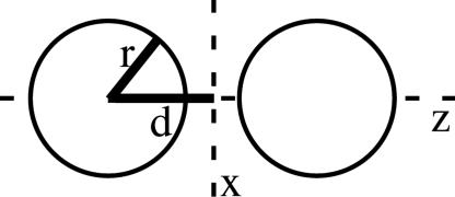
We begin by framing the calculation in general terms. In Fig. 1, two metallic spheres (with a known, complex dielectric constant) of identical radius r are spaced by a given separation 2(d - r) along the z axis. In the absence of retardation, the electromagnetic field is represented by an external static electric field, which in turn produces an enhanced local field around the particles. The variation of the field normal to the surface around one sphere results in a net force on that sphere. In general, the net force can be calculated by integration of the Maxwell stress tensor over the surface (17). When the field is oriented along the z axis, a large, attractive force is generated. This method is exact in the limit of large and small separations. (However, note that it does not give the scattering force that will push the center of mass in the laser-propagation direction.)
Fig. 1.
Outline of the problem.
In bispherical coordinates the variables are separable, allowing us to obtain a relatively simple solution. The bispherical coordinate system (μ,η,ϕ) is connected to the Cartesian coordinate system by
 |
[1] |
 |
[2] |
and
 |
[3] |
where c is a scaling factor determined by the radius of the sphere and the distance between them.
 |
[4] |
Surfaces of constant μ are spherical shells with radius  displaced from the origin by c/tanh(μ) so that the sign determines on which side of the origin they fall. The surface μ = 0 is the x, y plane and μ = ∞ defines a point. η defines a type of rotation in the x, z plane, and ϕ defines a certain meridian plane. One must use caution, because different authors choose different variable names. A full description of the coordinate system and its behavior can be found elsewhere (18). This sometimes cumbersome system is useful because the geometry of the problem leads to R separability of the Laplace equation in this case.
The first step in solving this problem is to calculate the potential between the two spheres by using the method of Aravind et al. (19). The normal electrostatic boundary conditions are
 |
[5] |
and
 |
[6] |
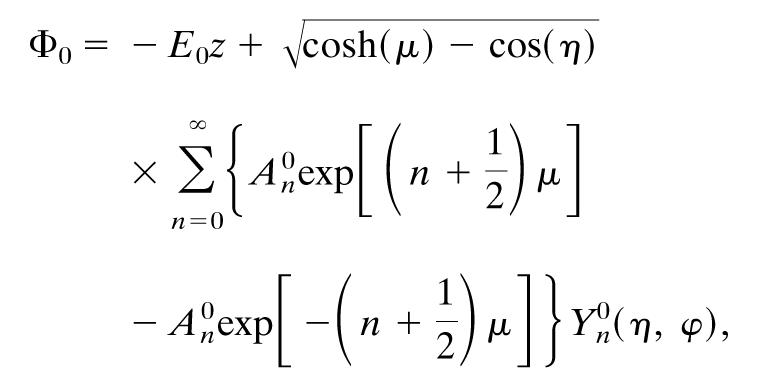
where Φ0 is the potential outside the spheres, and Φ1 is the potential inside them. The sign of μ specifies which sphere we are talking about. The applied field, from the incident laser light (it is the time-average Poynting vector), is fixed along the z axis, which simplifies matters further. The total potential is then
 |
[7] |
where E0 is the magnitude of the applied field, Yn0(η,ϕ) are the spherical harmonics that can be found in ref. 20, and A0n are expansion coefficients. The expansion coefficients are given by an infinite, linear set of equations set out by Aravind et al. (19) derived from the boundary conditions. An exact solution requires an infinite number of terms, so the series must be truncated at some point. Careful testing of the results along with other checks suggested by the authors convinced us that we were using a sufficient number of terms (name = 40). The main factor in determining the number of terms needed is the proximity of the two spheres.
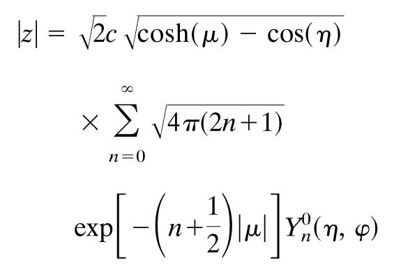
A key substitution is the convergent expansion for z that we use in solving this problem for the μ and η dependence of the electric field to remain separable.
 |
[8] |
Once we have the potential, we can find the electric field by taking the derivative. One must remember that in this coordinate system, scale factors are necessary. Also, the symmetry of the problem (the applied field along the intersphere separation axis) means that the answer is independent of ϕ.
 |
[9] |
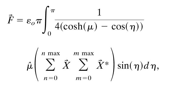
The force exerted on one of the spheres is computed by integrating the Maxwell stress tensor over the surface of the sphere. Here we follow the approach of Cruz and Ley-Koo (21). The Maxwell stress tensor (assuming no magnetic component) is given by
 |
[10] |
which we want to integrate over the surface of the sphere in the following way:
 |
[11] |
The surface element,  , is explicitly defined by Moon and Spencer (18). The force resulting from the applied field may now be computed. We solve for the expansion coefficients, use them to get the potential, take its derivative to get the electric field, and then integrate around the surface of the sphere as proscribed.
 |
[12] |
 |
[13] |
where the complex conjugate applies to the expansion coefficients, which have both real and imaginary parts.
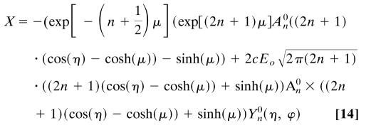 |
The unit vector  converts the answer back to Cartesian coordinates, so we compute the force in the z direction. The full expression can be found in ref. 21. The conditions of this problem reduce it to
 |
[15] |
Numerical Results
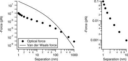
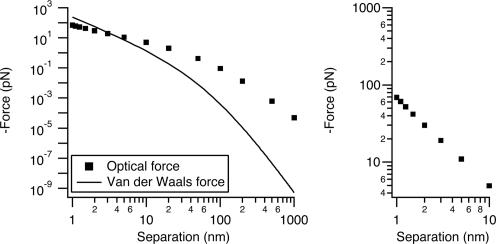
The force caused by 1 kW/cm2 intensity at 514-nm wavelength, polarized between two r = 30-nm Ag nanoparticles, is shown in Fig. 2. The intensity and wavelength are typical of many single-molecule and biological luminescence imaging experiments. In SERS wide-field Raman imaging experiments, the intensity is often 1 or 2 orders of magnitude lower (22, 23). We compare the optical force with the van der Waals force between the same particles calculated by using the Hammaker formulation. At 1-nm separation the van der Waals force is ≈100 pN, 2 orders of magnitude stronger than the optical force at this intensity. For comparison, Brownian motion exerts forces on particles in the low piconewton range (see ref. 24, particularly sections II and IV), molecular motors create forces in the 3- to 10-pN range (25), antigen-antibody interactions are 50-300 pN (26), and several nanonewtons will break a C—C bond (27). Thus, the van der Waals attraction (plus adhesive forces) should establish the junction geometry for touching particles in SERS experiments, and we would not expect geometry to vary as a function of laser power at these intensities.
Fig. 2.
A comparison of relevant forces. (Left) Van der Waals force and optical force calculated as a function of separation between two r = 30-nm Ag spheres in vacuum at an intensity of 1 kW/cm2 at 514-nm wavelength. For the van der Waals force we used a Hammaker constant, A = 4 × 10-20 J, and equations that can be found in ref. 28. (Right) An expanded view of the 1- to 10-nm range shows how rapidly the force increases over this interval.
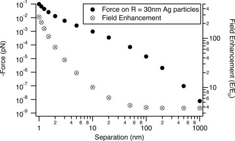
There are three separate regions in the optical force versus distance curve, corresponding to diameter 2r being much greater than, approximately equal to, or much less than the separation (z). The plot has a characteristic shape with a midrange plateau. A somewhat similar shape is also seen in Hammaker van der Waals plots versus distance (28). At short range, both the optical force and the electromagnetic-field enhancement factor rise very rapidly. As the separation decreases from 10 to 1 nm, the optical force increases by a factor of 100. Fig. 3 shows a plot of the enhanced electromagnetic field at the surface of one particle in the junction. This enhancement factor increases by a factor of 25 from 10- to 1-nm separation. Both effects occur as the optical electron polarization concentrates on the metal surfaces in the junction for short separations (6). The field-enhancement factor at 1-nm separation is ≈250, corresponding to an intensity enhancement of ≈5 × 10⁵ and a theoretical Raman enhancement of ≈2.5 × 10¹¹.
Fig. 3.
A comparison of the field enhancement at the surface of one sphere in the junction to the optical force from Fig. 2.
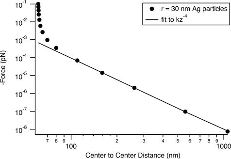
At long distance, the Hammaker plots fall off as z-7, whereas the optical force falls off as z-4; the optical-force curve (without retardation) crosses the van der Waals curve near 100 nm in Fig. 2. The optical force also falls off much more slowly than does the junction-field enhancement, which in Fig. 3 saturates at its single sphere value at separations larger than ≈30 nm. The z-4 behavior is seen more clearly in Fig. 4, in which the force on r = 30-nm particles is plotted as a function of center-to-center separation (rather than edge-to-edge separation). Figs. 2 and 4 also show that if one were simply to estimate the dipole-dipole interaction at long distance and then extrapolate down to a separation of a few nanometers, one would significantly underestimate the optical force.
Fig. 4.
Optical force for r = 30-nm Ag particles irradiated with 1 kW/cm2 intensity at a wavelength of 514 nm plotted as a function of center-to-center distance. These are the same data that are plotted in Fig. 2. At long range the interaction goes as z-4, which fits a simple dipole-dipole model. At short range the force is stronger than the dipole-dipole attraction by a factor of nearly 150.
Higher, MW/cm2 intensities in focused beams are used in other experiments to generate SERS spectra (25) and to optically trap single colloidal r = 30-nm Ag particles in water (29). Fig. 5 shows the optical force for an intensity of 5 MW/cm2 at 800 nm on Au particles. In this situation the optical force dominates van der Waals and is almost 1 nN at 1-nm separation. The comparison between Au and Ag is instructive. Table 1 compares Au and Ag at the two wavelengths for constant intensity (1 MW/cm2). The Ag force at 1 nm actually decreases by a factor of ≈150 when going from 514 to 800 nm. In a plot of the distance dependence, the fast rise below 10-nm separation seen for Ag in Fig. 2 at 514 nm is absent in the 800-nm plot (not shown). Five hundred and fourteen nanometers is near the dimer plasmon resonance peak for Ag; this resonance causes the large force. In comparison, the optical force between two silica particles is ≈3 orders of magnitude lower in Table 1.
Fig. 5.
Au particles (r = 30 nm) illuminated at 800 nm with 5 MW/cm2 of power. (Inset) The same dynamic range as that shown in Fig. 2 Inset to show that, for Au, the force does not increase as rapidly as it does for Ag. The Hammaker constant for Au is 10 × 10-20 J, 2.5 times larger than that of Ag.
Table 1. Optical force between r = 30 nm particles at a separation of 1 nm under 1 MW/cm2 illumination.
| 514 nm | 800 nm | |
|---|---|---|
| Ag | 97.4 pN | 5.39 pN |
| Au | 6.98 pN | 13.8 pN |
| Glass | 0.077 pN | 0.075 pN |
In Au the reverse behavior is observed: the force is low at 514 and a factor of ≈20 higher at 800 nm. In the range from 10- to 1-nm separation for Au at 800 nm wavelength in Fig. 5, the force increases by a factor of ≈14. Au is more resonant at 800 nm than at 514 nm.
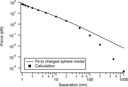
This model is an exact solution of Maxwell's equations at optical frequencies in the absence of retardation. We gain some physical insight by comparison to the electrostatic problem of the attraction between two perfectly metallic spheres, one charged and one grounded (21). Here force is related to the integral of the electric field between the spheres along the line of centers. This integral is the potential of one sphere relative to the other. We use the equation developed by Cruz (equation 6 of ref. 21), giving the force as a function of the potential difference. We fit to our calculated forces with the voltage difference as an adjustable parameter. The model fits the data for r = 30-nm Au particles extremely well at short range (Fig. 6). The fit corresponds to a voltage difference of 308 μV. The actual line integral of the electric field between the two spheres is ≈500 μV.
Fig. 6.
Fit of charged sphere model to our data for r = 30-nm Au particles. The resulting potential difference is 315 μV.
Discussion
We find that the 1 kW/cm2 and lower intensities typically used for wide-field Raman imaging generally should not affect junction geometry or produce photoaggregation. In an early single-molecule experiment, it was observed that the Raman scattering is reversibly superlinear (30) for most, but not all, single-molecule signals. It was suggested that this superlinearity occurs because of the molecule itself being pulled deeper into the junction by the local field gradient. At 10 W/cm2 incident power, the enhanced field in the junction is ≈1 MW/cm2, with a large gradient perpendicular to the line of particle centers. This gradient is sufficient to optically trap the molecule if it itself is resonant with the laser (17, 31).
At 1 MW/cm2 and higher intensities, two particles can be brought together; this is best done with Ag at visible wavelengths and Au in the near IR. An important aspect is that the optical force is longer range than the van der Waals force. At sufficient intensity it can overcome the long-range repulsive colloidal electrostatic Derjaguin-Landau-Verwey-Overbeek force and/or possible friction forces for particles on surfaces, depending on numerical magnitude. Once pulled together, the particles are bound by the 100-pN van der Waals force and adhesive forces. In principle, the optical force can be turned off and the particles will remain bound. At these high-incident intensities, specific molecules in the junctions may be destroyed by the extremely high enhanced junction intensity. In general, optical organization would be best done in the near IR to avoid particle heating or photoionization. The incident field intensity needs to be below ≈1010 W/cm2 (instantaneous power), where heating causes particles to melt, change shape, or even fragment (31), which is a real concern if short pulses are used.
A group of freely diffusing particles in two dimensions on a surface could be organized by optical forces. The laser polarization is a degree of freedom that allows us to manipulate the assembly process. With linear polarization, particles should form lines along the polarization direction and, depending on conditions, perhaps fuse as described above. In electrostatic fields, polarizable particles are known to form lines (32, 33). With unpolarized light incident normal to the surface, there should be a net aggregation (in both directions), because the attraction for laser polarization along the two-particle axis is stronger than the repulsion for polarization perpendicular to the two-particle axis. “Linearly arrayed gold nanoparticles,” reported by Murakoshi and Nakato (34), were produced by irradiation of aqueous Au colloidal particles with IR light on a Au flat surface. These authors suggested optical forces as the mechanism. As a point of reference, we calculate that the optical attractive force between two r = 3-nm Au particles separated by 2 nm and irradiated at 830 nm at an incident power of 109 W/cm2 is approximately equal to the aqueous Brownian-motion force on one particle. As mentioned in the introduction, there is also literature (12-14) on the photoinduced coagulation of noble metal aqueous colloids. There is no consensus as to the mechanism in these experiments: both photoionization reducing the Derjaguin-Landau-Verwey-Overbeek electrostatic stabilization and optical forces may be involved.
In the field of molecular electronics, thin Au metallic lines are used to make electrical contact to semiconductor nanowires and even to single molecules (35-38). Optical creation and fusing of a line of particles might be a way to produce a Au wire line too small to be made by lithography. Optical processing of a lithographic metallic wire might be a way to reduced internal grain boundary junctions and improve electrical conductivity. In the case of a single-molecule device, it might be a way to modify the source-drain junction spacing and/or molecular contact.
Finally, another place at which optical force perhaps plays a role is in IR laser photonucleated crystallization of optically transparent molecules in supersaturated solutions (39, 40). It was suggested that molecules are orientationally aligned by the GW/cm2 Nd:YAG laser, as occurs in the Kerr effect. Different crystal structures were obtained depending on laser polarization. We note that in standard thermodynamic nucleation theory, there is a critical nucleus size: smaller clusters spontaneously dissolve because of their high surface energy, whereas larger clusters spontaneously grow to bulk crystals (41). Optical forces may bring together two subcritical clusters and help fuse them. The force would depend on the index of the crystal being higher than the index of the solvent. We predict, then, that crystallization in this way works better the lower the index of the solvent.
Acknowledgments
We thank T. F. Heinz and W. B. Russel for valuable discussion and correspondence. This work was supported by Department of Energy Basic Energy Sciences (under Grant FG02-98ER14861), the Air Force Office of Scientific Research Multidisciplinary University Research Initiative program, and the National Science Foundation Nanocenter at Columbia (under Grant CHE-010110655).
Abbreviation: SERS, surface-enhanced Raman effect.
See accompanying Biography on page 1277.
This contribution is part of the special series of Inaugural Articles by members of the National Academy of Sciences elected on April 20, 2004.
References
- 1.Moskovits, M. (1985) Rev. Mod. Phys. 57, 783-826. [Google Scholar]
- 2.Schatz, G. (1984) Acc. Chem. Res. 17, 370-376. [Google Scholar]
- 3.Campion, A. & Kambhampati, P. (1998) Chem. Soc. Rev. 27, 241-250. [Google Scholar]
- 4.Otto, A., Mrozek, I., Grabhorn, H. & Akemann, W. (1992) J. Phys. Condens. Matter 4, 1143-1212. [Google Scholar]
- 5.Kamat, P. (2002) J. Phys. Chem. B 106, 7729-7744. [Google Scholar]
- 6.Jiang, J., Bosnick, K., Maillard, M. & Brus, L. (2003) J. Phys. Chem. B 107, 9964-9972. [Google Scholar]
- 7.Inoue, M. & Ohtaka, K. (1983) J. Phys. Soc. Jpn. 52, 3853-3864. [Google Scholar]
- 8.Michaels, A. M., Nirmal, M. & Brus, L. E. (1999) J. Am. Chem. Soc. 121, 9932-9939. [Google Scholar]
- 9.Xu, H. X., Bjerneld, E. J., Kall, M. & Borjesson, L. (1999) Phys. Rev. Lett. 83, 4357-4360. [Google Scholar]
- 10.Futamata, M., Maruyama, Y. & Ishikawa, M. (2004) Vib. Spectrosc. 35, 121-129. [Google Scholar]
- 11.Ashkin, A. (1997) Proc. Natl. Acad. Sci. USA 94, 4853-4860. [DOI] [PMC free article] [PubMed] [Google Scholar]
- 12.Satoh, N., Hasegawa, H., Tsujii, K. & Kimura, K. (1994) J. Phys. Chem. 98, 2143-2147. [Google Scholar]
- 13.Eckstein, H. & Kreibig, U. (1993) Z. Phys. D 26, 239-241. [Google Scholar]
- 14.Karpov, S. V., Slabko, V. V. & Chiganova, G. A. (2002) Colloid J. 64, 425-441. [Google Scholar]
- 15.Kimura, K. (1994) J. Phys. Chem. 98, 11997-12002. [Google Scholar]
- 16.Xu, H. & Kall, M. (2002) Phys. Rev. Lett. 89, 246802. [DOI] [PubMed] [Google Scholar]
- 17.Iida, T. & Ishihara, H. (2003) Phys. Rev. Lett. 90, 057403. [DOI] [PubMed] [Google Scholar]
- 18.Moon, P. & Spencer, D. E. (1988) Field Theory Handbook, Including Coordinate Systems, Differential Equations, and Their Solutions (Springer, New York), pp. 110-112.
- 19.Aravind, P. K., Nitzan, A. & Metiu, H. (1981) Surf Sci. 110, 189-204. [Google Scholar]
- 20.Jackson, J. D. (1998) Classical Electrodynamics (Wiley, New York), 3rd Ed., p. 98.
- 21.Cruz, A. C. & Ley-Koo, E. (2002) Rev. Mex. Fis. 48, 579-585. [Google Scholar]
- 22.Nie, S. M. & Emory, S. R. (1997) Science 275, 1102-1106. [DOI] [PubMed] [Google Scholar]
- 23.Kneipp, K., Wang, Y., Kneipp, H., Perelman, L. T., Itzkan, I., Dasari, R. R. & Feld, M. S. (1997) Phys. Rev. Lett. 78, 1667-1670. [DOI] [PubMed] [Google Scholar]
- 24.Einstein, A. (1956) Investigations on the Theory of the Brownian Movement, ed. Furth, R. (Dover, New York).
- 25.Bao, G. & Suresh, S. (2003) Nat. Mater. 2, 715-725. [DOI] [PubMed] [Google Scholar]
- 26.Gimzewski, J. K. & Joachim, C. (1999) Science 283, 1683-1688. [DOI] [PubMed] [Google Scholar]
- 27.Drexler, K. E. (1992) Nanosystems: Molecular Machinery, Manufacturing, and Computation (Wiley & Sons, New York).
- 28.Russel, W., Saville, D. & Schowalter, W. (1989) Colloidal Dispersions (Cambridge Univ. Press, Cambridge, U.K.), p. 135.
- 29.Prikulis, J., Svedberg, F., Kall, M., Enger, J., Ramser, K., Goksor, M. & Hanstorp, D. (2004) Nano Lett. 4, 115-118. [Google Scholar]
- 30.Michaels, A., Jiang, J. & Brus, L. (2000) J. Phys. Chem. B 104, 11965-11971. [Google Scholar]
- 31.Link, S., Burda, C., Nikoobakht, B. & El-Sayed, M. A. (2000) J. Phys. Chem. B 104, 6152-6163. [Google Scholar]
- 32.Park, C. & Robertson, R. E. (1998) Mater. Sci. Eng. A 257, 295-311. [Google Scholar]
- 33.Tao, R. & Jiang, Q. (1994) Phys. Rev. Lett. 73, 205-208. [DOI] [PubMed] [Google Scholar]
- 34.Murakoshi, K. & Nakato, Y. (2000) Adv. Mater. 12, 791-795. [Google Scholar]
- 35.Nazin, G. V., Qiu, X. H. & Ho, W. (2003) Science 302, 77-81. [DOI] [PubMed] [Google Scholar]
- 36.Ahlskog, M., Tarkiainen, R., Roschier, L. & Hakonen, P. (2000) Appl. Phys. Lett. 77, 4037-4039. [Google Scholar]
- 37.Ramanathan, K., Bangar, M. A., Yun, M., Chen, W., Mulchandani, A. & Myung, N. V. (2004) Nano Lett. 4, 1237-1239. [Google Scholar]
- 38.Farajian, A. A., Belosludoc, R. V., Mizuseki, H. & Kawazoe, Y. (2003) Phys. E 18, 253-254. [Google Scholar]
- 39.Garetz, B., Matic, J. & Myerson, A. (2002) Phys. Rev. Lett. 89, 175501. [DOI] [PubMed] [Google Scholar]
- 40.Zaccaro, J., Matic, J., Myerson, A. S. & Garetz, B. A. (2001) Cryst. Growth Des. Commun. 1, 5-8. [Google Scholar]
- 41.Kashchiev, D. & van Rosmalen, G. M. (2003) Cryst. Res. Technol. 38, 555-574. [Google Scholar]


