Abstract
Modern 3D printing technology can fabricate vascular phantoms based on an actual human patient with a high degree of precision facilitating a realistic simulation environment for an intervention. We present two experimental setups using 3D printed patient-specific neurovasculature to simulate different disease anatomies.
To simulate the human neurovasculature in the Circle of Willis, patient-based phantoms with aneurysms were 3D printed using a Objet Eden 260V printer. Anthropomorphic head phantoms and a human skull combined with acrylic plates simulated human head bone anatomy and x-ray attenuation. For dynamic studies the 3D printed phantom was connected to a pulsatile flow loop with the anthropomorphic phantom underneath. By combining different 3D printed phantoms and the anthropomorphic phantoms, different patient pathologies can be simulated. For static studies a 3D printed neurovascular phantom was embedded inside a human skull and used as a positional reference for treatment devices such as stents. To simulate tissue attenuation acrylic layers were added. Different combinations can simulate different patient treatment procedures.
The Complementary-Metal-Oxide-Semiconductor (CMOS) based High Resolution Fluoroscope (HRF) with 75μm pixels offers an advantage over the state-of-the-art 200 μm pixel Flat Panel Detector (FPD) due to higher Nyquist frequency and better DQE performance. Whether this advantage is clinically useful during an actual clinical neurovascular intervention can be addressed by qualitatively evaluating images from a cohort of various cases performed using both detectors. The above-mentioned method can offer a realistic substitute for an actual clinical procedure. Also a large cohort of cases can be generated and used for a HRF clinical utility determination study.
Introduction
Endovascular Image guided interventions (EIGI) [1] are modern day minimally invasive treatments for several neurovascular diseases such as strokes, aneurysms and arteriovenous malformations. The catheters are inserted through the femoral artery and guided into the treatment area under x-ray imaging. Once the diseased area is located, the treatment devices such as stents, coils and balloons are then deployed. During this stage it is critical to provide the interventionalist with the best real time imaging of the device deployment. To address this issue a high resolution fluoroscope (HRF) detector with a pixel pitch of 75um based on CMOS technology was previously developed [2]. Figure 1 shows the DQE comparison of the HRF (Dexela) detector with the state of the art FPD with a pixel size of 200um [3]. The DQE improvement clearly indicates that the HRF offers an advantage over the FPD. How much of this advantage is clinically relevant is a question that still needs to be addressed.
Figure 1.
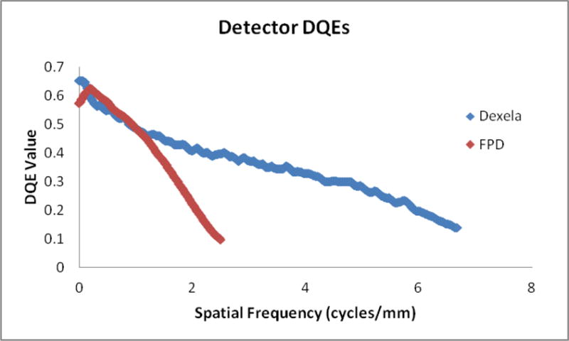
DQE comparison between the HRF (75 μm pixel) and FPD (194 μm pixel) detector
One approach to answer this question is to qualitatively evaluate images from a cohort of various clinical EIGI cases performed using both the detectors. Current day 3D printing technology has the ability to print vascular phantoms that are based on an actual human patient with a high degree of precision. This facilitates a very realistic simulation of an EIGI procedure so testing does not have to be performed during actual clinical procdures.
In this work we present two experimental setups using the 3D printed patient-specific neurovascular to simulate different patients with diseased anatomies. Using these setups, images simulating various clinical views of treatment devices and vascular anatomy were generated and are presented as results.
Methods
3D printed aneurysm model
Patient specific phantoms were 3D printed using the Objet Eden 260V printer from Stratasys, Eden Prairie, MN. Details involved in the 3D printing process, from acquisition of patient data to the end model generation are presented elsewhere [4] [5]. The basic vasculature consists of the ICA (Internal Carotid Artery) segments, MCA (Middle Cerebral Artery) branches (M1-M4 segments), bilateral A1 anterior cerebral artery segments connected to a single anterior cerebral artery and a single posterior communicating artery on the right side, thus allowing near complete Circle of Willis circulation and closely resembling the human intracranial circulation.
To simulate aneurysm treatments, 3D models with aneurysms added to the basic vasculature mentioned above were printed. Figure 2 shows an example of the bifurcated aneurysm model, with aneurysms in the MCA and ICA bifurcation segment.
Figure 2.
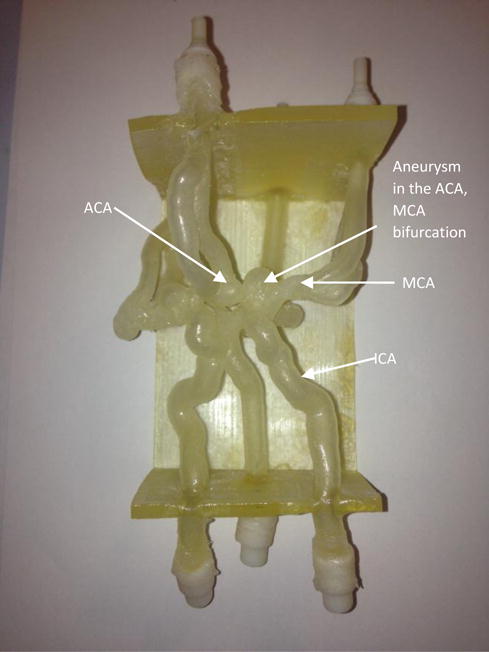
A 3D printed bifurcation aneurysm model.
ICA : Internal Carotid Artery
MCA: Middle Cerebral Artery
ACA: Anterior Communicating artery
Clinical view simulation setup
Simulation of patient anatomy was divided into 2 parts which will be used in both dynamic and static set-ups:
Neurovascular anatomy simulation: 3D printed aneurysm model was used to simulate the human cerebrovascular system in the Circle of Willis region.
Anatomical features simulation: Three anthropomorphic head phantoms (RS-240T by Radiology Support Devices Inc., CA, SK150 by The Phantom Laboratory, NY and PBU-50 by Kyoto Kagaku Co. LTD., Japan), and one human skull in combination with acrylic PMMA plates of various thickness were used to simulate human head bone anatomy and x-ray attenuation.
To simulate the clinical EIGI images obtained during the interventions two different experimental setups were designed.
-
Static study setup: Figure 3 shows the schematic of the experimental setup for static studies. A 3D printed neurovascular phantom was embedded inside a human skull. This was used as a positional reference to place treatment devices such as stents and coils. To simulate tissue attenuation, acrylic layers were added in the field of view (FOV). Different combinations of acrylic layers can simulate different patients, and by changing the placement of the device and the x-ray beam angles different clinical views of a device can be generated.
Figure 4 shows an example simulation setup. A 4.25 mm × 20 mm pipeline embolization device (PED) flow diverter stent was placed in the left side M1 segment of the 3D model. Three inches of acrylic were placed underneath the skull. Images from both the HRF and FPD detectors were acquired at the same exposure conditions as determined by the automatic exposure control of the FPD system. The object to imager distance was kept the same for both detectors. Images from acquisitions are presented in the result section.
-
Dynamic study setup: Figure 5 shows the schematic of the experimental setup. The 3D printed phantom was connected to a flow loop. The circulating fluid was water or a glycerin-water mixture when simulating blood and a pulsatile pump was used to simulate the blood pressure. To simulate patient attenuation and anatomical features the anthropomorphic phantoms were placed underneath the table. By combining different 3D printed phantoms and the anthropomorphic phantoms, different patients with diseased pathologies can be simulated.
Figure 6 shows an example. The RS-240T phantom is placed underneath the table to simulate patient anatomical features and x-ray attenuation. The HRF is in the active field of the view making it the primary acquisition detector. The aneurysm was treated with 1 coil using the x-ray images from both the HRF and FPD detectors. The images from this study are presented in the results section.
Figure 3.
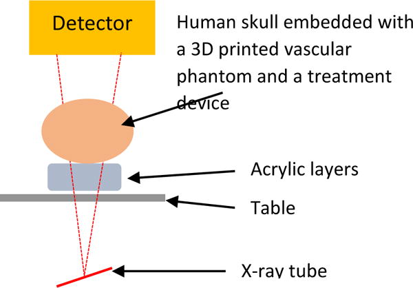
Experimental setup for the static studies. Different combinations of acrylic layers, position of the stent and different stents can simulate different patient treatment procedures.
Figure 4.
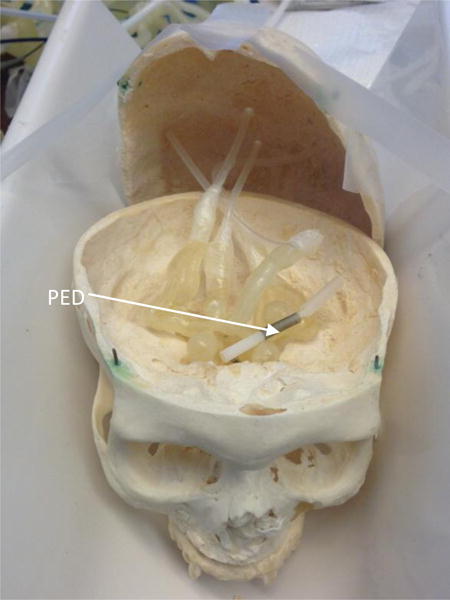
A 4.75mm × 20mm Pipeline Embolization Device (PED) placed in the left M1 segment of the embedded 3D model
Figure 5.
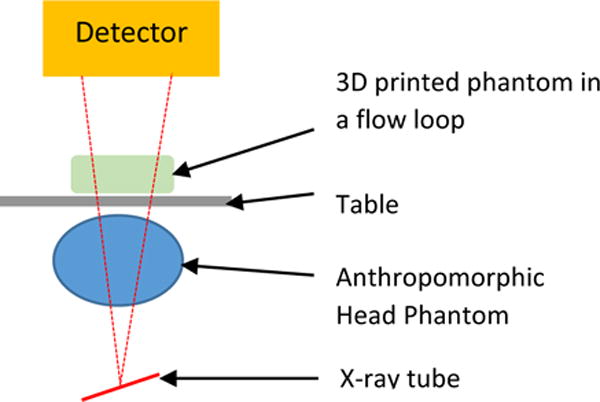
Experimental setup for the dynamic studies. Combining different 3D printed phantoms and anthropomorphic head phantoms simulates different patients with diseased anatomies
Figure 6.
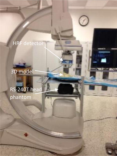
Dynamic study setup with HRF in FOV.
Results
Static study setup: Figures 7A and 7B show the image of the PED acquired from the HRF detector and FPD, respectively.
Figure 7.
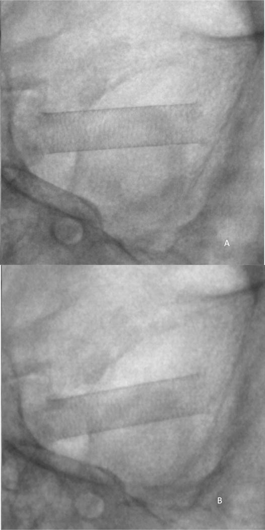
Simulated clinical view of the PED, using the static study setup shown in figure 3 and 4.
Cine exposure conditions: 80kVp 160mA 6.3ms, small focal spot
A) Image acquired using HRF detector
B) Image acquired using FPD
Dynamic study setup: Figure 8 shows the digital subtraction angiography image obtained using the HRF detector indicating the aneurysm morphology and location. Figure 9A is a single image from a sequence and figure 9B is the corresponding background subtracted roadmap image showing the coil mass fully deployed into the aneurysm.
Figure 8.
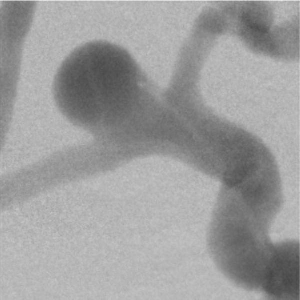
Digital subtraction angiography image, indicating a right side MCA and ACA bifurcation aneurysm. The image was acquired using the HRF detector. The dynamic study setup shown in figure 5 was used to simulate clinical x-ray attenuation conditions.
Figure 9.
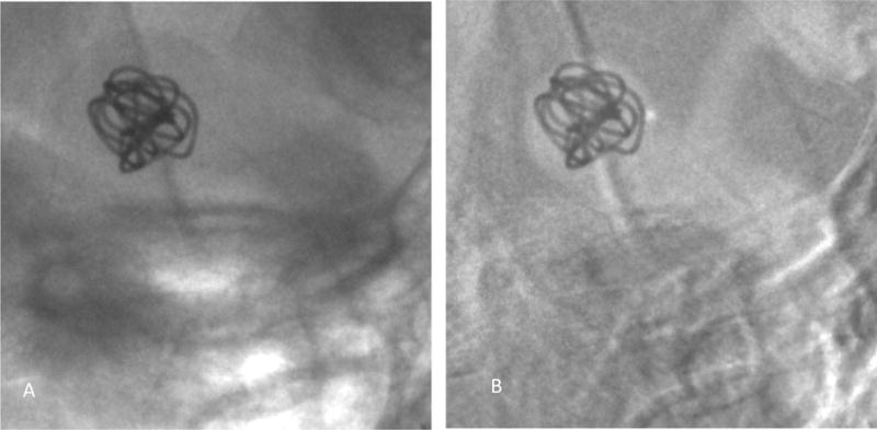
A single image from a sequence acquired using the HRF detector showing the coil being fully inserted into the aneurysm.
A) Image showing the device with the background anatomy
B) Background subtracted roadmap image
Figure 10 shows the digital subtraction angiography image obtained using the FPD detector indicating the aneurysm morphology and location. Figure 11A is a single image from a sequence and figure 11B is the corresponding background subtracted roadmap image showing the coil mass fully deployed into the aneurysm.
Figure 10.
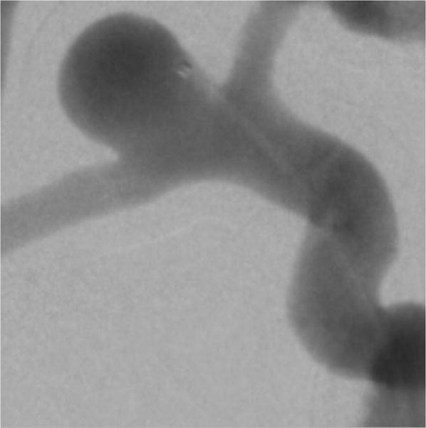
Digital subtraction angiography image, indicating a right side MCA and ACA bifurcation aneurysm. The image was acquired using the FPD. The dynamic study setup shown in figure 5 was used to simulate clinical x-ray attenuation conditions.
Figure 11.
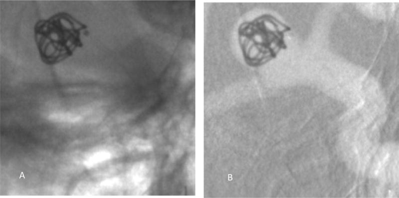
A single image from a sequence acquired using the FPD showing the coil being fully inserted into the aneurysm.
A) Image showing the device with the background anatomy
B) Background subtracted roadmap image
Discussion
The purpose of this work was to simulate x-ray clinical views of patient anatomy and treatment devices. 3D printed patient specific neurovascular phantoms combined with anatomical feature phantoms offer the advantage of simulating various patients with diseased anatomy. The dynamic and static study setup offer the advantage of simulating multiple clinical views with varying patient anatomy and treatment devices.
With the static study setup, images of a treatment device can be acquired using both detectors (HRF and FPD) with the same exposure, object magnification and field of view. As shown in figures 7A and 7B the view of the PED is similar to the one experienced in the clinic. To do this study in the clinic during an actual intervention would require additional images of the same object to be acquired at the cost of increased patient dose and operating time. Doing such a study with a large cohort of cases could be practically challenging. To do the study, sets of images such as these will be shown to clinicians for relative semi-quantitative scoring for both a static set as well as a dynamic set.
With the dynamic study setup, the visualization of diseased vasculature as seen from figures 8 and 11 and the treatment devices along with the anatomical features as seen from figures 10, and 13 come realistically close to an actual clinical intervention image considering that the figures shown here represent only one of the images in the sequences that will be viewed.
To establish clinical value, the simulated clinical views of the patient anatomy and treatment devices can be used for image comparison between the two detectors. For quantifying the clinical performance of imaging detectors, the images of the simulated views or sequences can be presented to blinded observers and the image quality can be evaluated based on criteria such as comfort level in visualization of vascular anatomy, and visibility of flow, micro catheter, device structures, etc.
Conclusions
Patient-specific vascular phantoms can be 3D printed and used with anthropomorphic phantoms and attenuators to simulate a variety of patient endovascular procedures. These simulations can be used for image receptor or device evaluation or for treatment staging. The setups described here can be used to generate a large cohort of simulated x-ray clinical images or image sequences of the patient anatomy and the treatment device deployments. Such images can be used for semi-quantitative image quality comparison studies to assess the clinical tasks where the new highresolution fluoroscope detector may have significant benefit.
Acknowledgments
NIH grant R01EB2873 and equipment support from Toshiba Medical Systems Corp.
References
- 1.Rudin S, Bednarek DR, Hoffmann KR. Endovascular image guided interventions (EIGIs) Med Phys. 2008 Jan;35:301–309. doi: 10.1118/1.2821702. http://www.ncbi.nlm.nih.gov/pubmed/18293585. [DOI] [PMC free article] [PubMed] [Google Scholar]
- 2.Jain A, Bednarek DR, Rudin S. Experimental and theoretical performance analysis for a CMOS-based high resolution image detector. Proc SPIE Int Soc Opt Eng. 2014;9033:90333P. doi: 10.1117/12.2043053. [DOI] [PMC free article] [PubMed] [Google Scholar]
- 3.Singh V, Jain A, Bednarek DR, Rudin S. Relative object detectability (ROD): a new metric for comparing x-ray image detector performance for a specified object of interest. Proc SPIE Int Soc Opt Eng. 2014;9033:90335. doi: 10.1117/12.2043504. [DOI] [PMC free article] [PubMed] [Google Scholar]
- 4.Russ M, O’Hara R, Setlur Nagesh SV, Mokin M, Jimenez C, Siddiqui A, Bednarek D, Rudin S, Ionita C. Treatment Planning for Image-Guided Neuro-Vascular Interventions Using Patient-Specific 3D Printed Phantoms. Proc SPIE Int Soc Opt Eng. 2015;9417 doi: 10.1117/12.2081997. [DOI] [PMC free article] [PubMed] [Google Scholar]
- 5.Ionita CN, Mokin M, Varble N, Bednarek DR, Xiang J, Snyder KV, Siddiqui AH, Levy EI, Meng H, Rudin S. Challenges and limitations of patient-specific vascular phantom fabrication using 3D Polyjet printing. Proc SPIE Int Soc Opt Eng. 2014;9038:90380M. doi: 10.1117/12.2042266. [DOI] [PMC free article] [PubMed] [Google Scholar]


