Abstract
Complex vascular anatomies can cause the failure of image-guided endovascular procedures. 3D printed patient-specific vascular phantoms provide clinicians and medical device companies the ability to preemptively plan surgical treatments, test the likelihood of device success, and determine potential operative setbacks. This research aims to present advanced mesh manipulation techniques of stereolithographic (STL) files segmented from medical imaging and post-print surface optimization to match physiological vascular flow resistance. For phantom design, we developed three mesh manipulation techniques. The first method allows outlet 3D mesh manipulations to merge superfluous vessels into a single junction, decreasing the number of flow outlets and making it feasible to include smaller vessels. Next we introduced Boolean operations to eliminate the need to manually merge mesh layers and eliminate errors of mesh self-intersections that previously occurred. Finally we optimize support addition to preserve the patient anatomical geometry. For post-print surface optimization, we investigated various solutions and methods to remove support material and smooth the inner vessel surface. Solutions of chloroform, alcohol and sodium hydroxide were used to process various phantoms and hydraulic resistance was measured and compared with values reported in literature. The newly mesh manipulation methods decrease the phantom design time by 30 – 80% and allow for rapid development of accurate vascular models. We have created 3D printed vascular models with vessel diameters less than 0.5 mm. The methods presented in this work could lead to shorter design time for patient specific phantoms and better physiological simulations.
Keywords: 3D Printing, Patient-Specific, Aneurysms, Vascular Phantoms, CTA Segmentation
1. INTRODUCTION
3D printed, patient-specific vascular flow phantoms are relatively new benchtop tools that have been developed by our group in the past few years1,2. The purpose of these phantoms is to provide accurate treatment planning for patients with cardiovascular disease; to traverse or treat anatomies that include severe stenoses, uncommon vessel bifurcations, tortuous vessels, or arches that impede the transition of the catheter to the treatment site. Cardiovascular disease, including stroke, is the leading cause of death (30% of deaths) in the world3. It also accounts for 12% of the total health expenditures in the United States (as of 2011), more than any other diagnostic group4.
Endovascular surgeries are minimally invasive procedures which incur shorter patient recovery times and lower mortality rates among individuals with vascular diseases5. Physicians are able to make a judgment on which device, or devices, to use based on medical images, but complications can still arise. Unforeseen challenges during surgery can lead to inaccurate or total device misplacement6,7, vessel injury, thrombolytic events, and increased radiation dose to the patient due to prolonged operating time8–15.
3D printed models provide physicians the ability to operate on an exact replica of patient anatomy, with similar flow conditions. These models allow for improved treatment planning, provide realistic training tools, and may lead to the expedited development of endovascular devices1,2. We have optimized the pre- and post-print workflow to create complex 3D printed phantoms in a reasonable time with physiologically relevant properties.
Vascular phantoms in this study were created from various medical imaging scans, including aortic, cardiac, and cerebral geometries. The 3D printed patient-specific geometries are based on CT, MRI, and CBCT acquisitions of patient anatomy relevant to their respective treatment. Figure 1 outlines the process of events required to 3D print a model of a patient’s anatomy. The medical images are acquired for the patient, vessels are segmented based on contrast and exported as an STL file, the STL file mesh is manipulated to remove errors and add a vessel wall thickness and support structure, and then the model is 3D printed using an Objet Eden 260V Polyjet 3D printer (Objet-Stratasys, Inc., Eden Prairie, MN). This printer is capable of printing 17 different materials, both rigid and flexible, in 16 μm layers, thus excelling at printing fine detail, complex geometries, and thin walls. For the TangoPlus material, a flexible photopolymer used to print the phantoms, nominal resolution in the z-axis is 32 μm, and up to 200 μm for in plane accuracy. This paper addresses advanced mesh-manipulation methods of STL files used to create 3D printed patient-specific flow phantoms as well as post-print processing of the model surfaces.
Figure 1.
Flow chart showing the manufacturing process for 3D printing patient-specific phantoms (Left Internal Carotid Artery shown above).
Acquired 3D reconstructed volumes of the patient anatomy are loaded into a Vitrea 3D Station (Vital Images, Inc., Minnetonka, MN). This software allows the user to segment the vascular geometry based on contrast using a marching cubes algorithm. The software also allows geometries to be selected and modified per individual DICOM slices in the coronal, sagittal, and transverse planes. Superfluous smaller branches can be trimmed, but we have developed new methods to include these vessels beneficially in the final models. Patients that suffer from deep brain aneurysms and complications can benefit from treatment planning using these models.
The geometry is then exported as an STL file and imported to Autodesk Meshmixer software (www.MeshMixer.com). The segmented STL file provides the general vascular anatomy of the patient, but it is a single-layer, continuous mesh with fragments from neighboring anatomical structures and often contains vessels that are conjoined due to their close proximity within the patient or poor contrast in the image. The imaging modality used to acquire the patient geometries is the limiting factor in resolution in comparison to the mesh manipulations of the STL file and the resolution of the 3D printer.
Post-print processing of the phantoms has increased the similarity of these 3D printed models to the physiological conditions of vessels in vivo. The 3D printing process requires manual support material removal. However, with very small vessels, the residue of this support material can be very challenging to remove and may negatively affect the flow path or even the transversal of a catheter within the model. We have found a new way to efficiently remove this residue with a sodium hydroxide surface coating.
Once the vascular models are 3D printed and cleaned of support material, they can be employed for imaging testing and treatment planning using a closed-flow loop and a peristaltic pump. Patient operations are time-sensitive and the use of patient-specific phantoms offers a feasible timeframe for treatment planning and device testing. In vitro mock procedures have proven useful in various studies involving endovascular interventions published by Mokin et al16, 17. This research introduces new design and post-print processing methods that differ from and advance previous research in this area of study.
2. MATERIALS AND METHODS
2.1 Mesh Manipulation
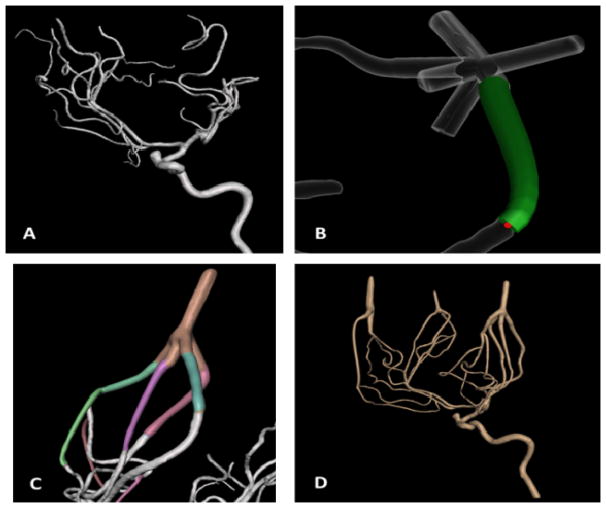
Smaller vessels, which were previously trimmed during segmentation to reduce the number of outlets, could negatively affect the reliability of a flow loop for contrast-based imaging, flow evaluation, or device testing. Using a new approach, these smaller vessels can be merged distally from their bifurcations into one another using an STL file shown in Figure 2. The ‘add tube’ function in Meshmixer easily allows the user to join up to five vessels into a single flow outlet, reducing the number of vessels removed and contributing to a more accurate representation of the patient anatomy. This function lets the user choose the start and end radius of the added tube and the degree of curvature in between. Reducing the number of flow outlets is not only more practical in the sense of connecting the model to a flow loop, but it also maintains the flow through even the smallest vessels within the phantom. By adjusting the widths of the joined vessels, the resistance in each vessel is manipulated to create a steady flow loop.
Figure 2.
(A) The unedited STL file of a left internal carotid artery. (B) ‘Add tube’ function for merging vessels. (C) A completed flow outlet. (D) The edited mesh before adding a thickness and support.
The segmented STL files initially need to be cleaned and edited to remove fragments, smooth inconsistencies in the mesh, and separate joined vessels. Once this is completed, the single-layer mesh needs a thickness and a support structure depending on the type of model. Previous methods for completing these tasks required extensive post-extrusion cutting and stitching at numerous locations in the model.
The use of Boolean operations, namely Boolean unions, makes this process much more efficient. Previously, to create a vessel wall thickness, the initial mesh layer needed to be duplicated and extruded to the desired thickness, usually 2.0 mm. The extrusion caused significant overlaps and self-intersections of the mesh at the location of bifurcations and neighboring vessels1. The 3D printer is unable to account for these errors and cannot print the file. 4 to 8 hours would be required to cut and re-stitch the mesh, depending on the complexity of the geometry. The ‘make solid’ function in Meshmixer creates a separate STL mesh of the desired thickness using Boolean unions to correct these errors all in a single step. The creation of a separate mesh is also beneficial to combining the outer thickness to support structures in a single step. The outer mesh of the vessel geometry and the mesh of the support structure were required to be cut out and then re-stitched in order to create a continuous surface that the 3D printer could print. Boolean unions allow us to take the outer mesh of the vessel geometry and combine it with the support structure in a single step.
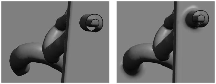
The Boolean operators are also beneficial in the sense that they re-mesh the surfaces that are being joined, maintaining the shapes of the involved meshes. A rectangular support structure, for example, has very few triangles and when cut and stitched to another structure, the mesh will deform and the support structure will require additional mesh manipulations. Figure 3 shows an example of the Boolean union method that efficiently combines the vascular model with the support structure. This quick step process greatly reduces the time required to merge the desired vascular model with a scaffold that ultimately allows for ease of use during flow and imaging testing.
Figure 3.
The before (left) and after (right) result of using a Boolean union for adjoining the outer layer of the vascular mesh to the support structure. The Boolean union smoothly combines the two meshes without affecting the inner layer of the vascular mesh.
In addition to Boolean operations and outlet manipulations, there is a need to preserve the anatomical positions of the 3D printed models. The support structures mentioned above are sufficient for holding the inlets and outlets, but due to the flexibility of the TangoPlus material, the vessels in between are pulled down by gravity. For cerebral and coronary arteries in a patient, there is a significant amount of soft tissue that keeps these structures from being drastically pushed such as the navigation of a catheter. Support structures are added during the mesh manipulation to keep the anatomical accuracy of the models for contrast imaging testing and treatment planning. Due to the currently high, although falling costs of 3D printing material, these structures are minimalized in size.
2.2 Post-Print Processing
The phantoms are printed with a support material, SUP705, which must be manually cleaned out before the phantoms can be used. A combination of water and ethanol is used to loosen the material, while applied force, catheters and guidewires are used to physically break apart the support material within the deeper vascular structures. Despite thorough cleaning, residual support material still remains within the lumen of the models, increasing the hydraulic resistance when the models are connected to a flow loop.
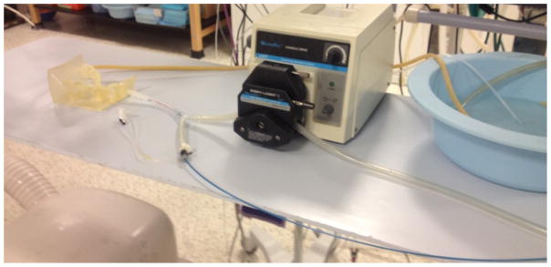
A device testing prototype was set up which consisted of a breadboard with two pressure sensors powered by a 6V power supply. LabVIEW was used to acquire the readings from these sensors which were interfaced to the NI USB-6211 Multifunction DAQ. Figure 4 shows the setup of the apparatus for the coronary model. The pressure sensors were calibrated to give a pressure reading in mmHg for a certain input voltage in mV. Coronary artery phantoms cleaned with water, 5% chloroform and a solution of sodium hydroxide were tested with water to get their respective hydraulic resistances. A motor was used to drive water through the phantoms and the flow rate of 0.22 L/min was measured using a transit time ultrasonic flowmeter. For a particular flow rate, the differential pressure at the two ends of the phantom was measured using the pressure sensors. Hydraulic resistance was calculated in (dynes-sec)/ cm5 by dividing the obtained differential pressure by the flow rate.
Figure 4.
Setup for acquiring the hydraulic resistances of three coronary phantom replicas.
2.3 Model Imaging
In order to image the models, rubber tubing is connected to the inlet and outlets of the model. A peristaltic pump is used to drive fluid through the system, simulating realistic circulatory conditions. A catheter is used to inject contrast agent into the model while the pump is in use. Figure 5 shows the setup of the system in an angiograph suite. X-ray images were taken at a rate of 6 frames per second and digital subtraction angiography was used to view the delivery of contrast agent through the vascular model.
Figure 5.
Closed flow loop setup for acquiring DSA images of the patient-specific vascular flow phantom.
3. RESULTS
3.1 Mesh Manipulation Results
The process of fabricating 3D printed, patient-specific phantoms has been streamlined in the past few years. Starting with the acquisition of patient geometries, the segmentation time using Vitrea has not changed drastically and still ranges from 0.5 – 2 hours, depending on the complexity, volume, and contrast within the vessels. The overall mesh manipulation period, which originally ranged from 10–30 hours, can now be completed in 1–12 hours, which again depends on the complexity, surface area, and errors of the original mesh.
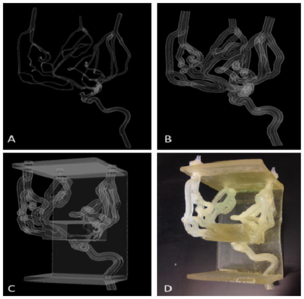
With these new advanced mesh-manipulation techniques, we have created models with more complex geometries. Figure 6 shows the stages of the mesh-manipulation process, from the completed single layer mesh STL to the printed and cleaned model of a right internal carotid artery including the anterior communicating and middle cerebral arteries extended to the superfluous arteries down to a diameter of 0.7 mm. The ability to employ patient-specific phantom use for pre-operative training and device testing before surgeries is becoming more feasible. A patient’s vascular anatomy can be segmented from medical imaging scans, modified using the aforementioned mesh-manipulation techniques, and 3D printed within a day.
Figure 6.
(A) Single layer mesh geometry (B) Vessel wall thickness and the inlet and outlets (C) Addition of the support structure (D) Printed and cleaned phantom
3.2 Post-Print Processing Results
The post-print processing of the vascular flow phantoms has made the use of these phantoms more than just a geometrical accuracy. When the support material is removed, there remains some residual material that water and ethanol cannot dissolve. Preliminary results showed that sodium hydroxide was the best solvent to the support material, SUP705. Scanning electron microscopy (SEM) showed that prolonged exposure of the inner lumen of the models to a solution of sodium hydroxide smoothed the surface. Figure 7 shows the SEM images of a TangoPlus slice after being flushed with sodium hydroxide for 1, 2, and 3 minutes. After 3 minutes, the surface of the inner lumen is smoother, leading to decreased hydraulic resistance.
Figure 7.
The SEM images of a TangoPlus slice flushed with sodium hydroxide after (A) 1 minute (B) 2 minutes and (C) 3 minutes
The average systemic arterial resistance in the body ranges from 700–1600 (dynes-sec)/cm5. The hydraulic resistances measured in the coronary phantoms treated with the three solvents, using water as the flow medium, were above this value, but the sodium hydroxide solution showed the most promising results. Table 1 outlines the results of the hydraulic resistance for the phantoms treated with the three different solvents. A flow rate of 0.22 L/min was used to simulate the cardiac output of blood to the coronary arteries. Sodium hydroxide treatment resulted in an average hydraulic resistance of 83% more than the maximum reported value for systemic arterial resistance. Water and chloroform treatment of the phantoms resulted in an increase in hydraulic resistance of almost 200% and 350%, respectively. Chloroform showed the maximum flow resistance, whereas sodium hydroxide showed the minimum. Hence, we can conclude the solvent used to post-process the surface of the phantoms has a significant effect on the differential pressure and the hydraulic resistance of the liquid flow.
Table 1.
Comparison of the hydraulic resistances in a coronary model treated with three solvents
| Liquid | Flow rate L/min | Hydraulic Resistance (dynes · sec)/cm5 | Percent Difference in Hydraulic Resistance |
|---|---|---|---|
| Reported Values | ~ 0.22 | 1600 | - |
| Sodium Hydroxide | 0.22 | 2925 ± 700 | ~ 83 % |
| Water | 0.22 | 4935 ± 800 | ~ 200 % |
| Chloroform | 0.22 | 7077 ± 900 | ~ 350% |
3.3 Model Imaging Results
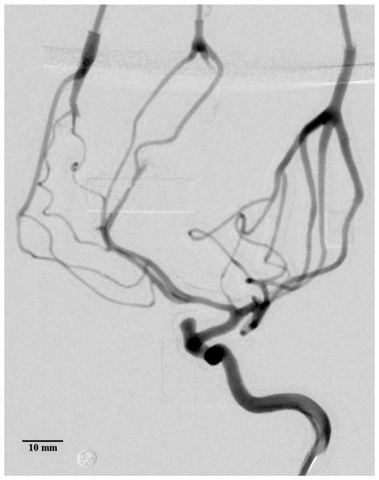
X-ray and DSA are used to verify the accuracy and compatibility of the small vessels in the 3D printed model. Contrast was injected into the model in conjunction to the peristaltic pump. The resulting geometry is almost identical to the geometry of the initial image segmentation. Figure 8 and Figure 9 show the patient-specific model geometry. The accuracy decreases towards the outlets as they are manipulated in order to reduce the total number of branches.
Figure 8.
Average DSA of the contrast bolus release in a 3D printed model of the left internal carotid artery. Inner vessel diameters as small as 0.45–0.50 mm were measured. Some of the support material in the distal regions could not be removed, blocking the flow of contrast. The circular marker has a diameter of 4.76 mm.
Figure 9.
DSA showing the arrival and dissipation of the contrast bolus. The circular marker has a diameter of 4.76 mm.
4. DISCUSSION
3D printed, patient-specific vascular flow phantoms provide unparalleled treatment planning and device testing opportunities for treating patients with vascular diseases. These models are accurate representations of patient anatomy and can be processed to further mimic physiological conditions. By optimizing the bench-top model testing to treat vascular disease, treatment planning, device testing, and interventionist training become more personalized to the patient, ultimately leading to fewer device failures in animal and clinical trials.
Advanced fabrication techniques allow us to manufacture patient-specific flow phantoms to greater detail in a shorter time period. Outlet manipulations for joining superfluous vessels reduces the number of flow outlets, includes a more accurate vascular anatomy, and removes flow-testing complications due to too many outlets. Boolean operations for adding a vessel wall thickness and support structure favorably reduce the STL mesh manipulation time. Support additions provide more accurate anatomical positioning for flow-testing and treatment planning.
The Boolean unions used in MeshMixer and described in this paper are explained in Schmidt’s thesis18, the groundwork written by the creator of the software. Polygon meshes are generated by defined vertices in 3D space and each continuous mesh is considered a part. In order for the software to perform a Boolean union of two parts, there must be an intersection of the parts, which is actually a multitude of intersections by each polygonal face of each part. The software employs a Boolean union operation without intersection, such that the intersecting and overlapping faces are deleted and then re-stitched to create one new part. Due to the deletion of the polygon faces of both parts at the intersection, the software uses a smoothing function that preserves the edges of the parts near the intersection.
After the necessary mesh manipulation and 3D printing of the patient-specific phantoms, the post-processing techniques we have developed add additional benefits to their use in treatment planning. Not only does the sodium hydroxide surface coating reduce hydraulic resistance, it also provides an expedited support material removal process by degrading the support material in smaller vessels that otherwise pose as a tedious and challenging task.
Phantoms with vessels as small as 450 um were created in order to explore the limitations of the TangoPlus material and the 3D printer. The 3D printer has a minimum resolution of 32 um which means it is feasible to print even smaller vessels. However, the challenge in printing vessels of such small sizes lies in the ability to clean out the support material after 3D printing. The new methods proposed in this paper using sodium hydroxide as a cleaning solution may allow us to create vascular phantoms with smaller vessel diameters.
By optimizing the development of 3D printed patient-specific vascular flow phantoms, complex endovascular surgeries can be performed with more information about challenging anatomies and device specifications without any additional patient testing.
5. CONCLUSIONS
Patient-specific vascular flow phantoms provide interventionists the ability to efficiently train pre-operatively and determine treatment solutions before operating on patients with complex vascular anatomies. These models are also a standardized experimental platform for device testing trials. Using advanced mesh-manipulation methods, such as outlet manipulations and Boolean unions with STL files, greatly reduces the manufacturing time of 3D printed patient-specific flow phantoms. The mesh-manipulation stage has been the most time-consuming and we significantly shortened it by 30– 80%, depending on the complexity and size of the patient geometry. Treatment of the models with sodium hydroxide reduces the hydraulic resistance of the phantoms, a difference of ~83% between the treated phantoms and physiological conditions. The DSA images of the 3D printed left internal carotid artery in this study prove that it is feasible to use this technology for vessels as small as 0.45 mm in diameter. Patient-specific phantoms represent a versatile benchtop tool and a unique learning opportunity for physicians and the endovascular field as a whole.
Acknowledgments
This work has been partially supported by NIH Grant R01EB002873
References
- 1.Ionita CN, Mokin M, Varble N, Bednarek DR, Xiang J, Snyder KV, et al. Challenges and limitations of patient-specific vascular phantom fabrication using 3d polyjet printing. Proc SPIE Int Soc Opt Eng. 2014;9038:90380M. doi: 10.1117/12.2042266. [DOI] [PMC free article] [PubMed] [Google Scholar]
- 2.Russ M, O’Hara R, Setlur Nagesh SV, Mokin M, Jimenez C, Siddiqui A, et al. Treatment planning for image-guided neuro-vascular interventions using patient-specific 3d printed phantoms. Proc SPIE Medical Imaging. 2015;9417:941726–941726. doi: 10.1117/12.2081997. [DOI] [PMC free article] [PubMed] [Google Scholar]
- 3.Go AS, Mozaffarian D, Roger VL, Benjamin EJ, Berry JD, Borden WB, et al. Heart disease and stroke statistics--2013 update: A report from the American heart association. Circulation. 2013;127:6–245. doi: 10.1161/CIR.0b013e31828124ad. [DOI] [PMC free article] [PubMed] [Google Scholar]
- 4.Mozaffarian D, Benjamin EJ, Go AS, Arnett DK, Blaha MJ, Cushman M, et al. Heart disease and stroke statistics--2015 update: A report from the american heart association. Circulation. 2015;131:29–322. doi: 10.1161/CIR.0000000000000152. [DOI] [PubMed] [Google Scholar]
- 5.Molyneux AJ, Kerr RS, Yu LM, Clarke M, Sneade M, Yarnold JA, et al. International subarachnoid aneurysm trial (isat) of neurosurgical clipping versus endovascular coiling in 2143 patients with ruptured intracranial aneurysms: A randomised comparison of effects on survival, dependency, seizures, rebleeding, subgroups, and aneurysm occlusion. Lancet. 2005;366:809–817. doi: 10.1016/S0140-6736(05)67214-5. [DOI] [PubMed] [Google Scholar]
- 6.Broadbent LP, Moran CJ, Cross DT, Derdeyn CP. Management of neuroform stent dislodgement and misplacement. AJNR. 2003;24:1819–1822. [PMC free article] [PubMed] [Google Scholar]
- 7.Lubicz B, Collignon L, Raphaeli G, De Witte O. Pipeline flow-diverter stent for endovascular treatment of intracranial aneurysms: Preliminary experience in 20 patients with 27 aneurysms. World Neurosurgery. 2011;76:114–119. doi: 10.1016/j.wneu.2011.02.015. [DOI] [PubMed] [Google Scholar]
- 8.Nuis RJ, Piazza N, Van Mieghem NM, Otten AM, Tzikas A, Schultz CJ, et al. In-hospital complications after transcatheter aortic valve implantation revisited according to the valve academic research consortium definitions. Catheterization and Cardiovascular Interventions: Official Journal of the Society for Cardiac Angiography & Interventions. 2011;78:457–467. doi: 10.1002/ccd.23018. [DOI] [PubMed] [Google Scholar]
- 9.Guinot PG, Depoix JP, Etchegoyen L, Benbara A, Provenchere S, Dilly MP, et al. Anesthesia and perioperative management of patients undergoing transcatheter aortic valve implantation: Analysis of 90 consecutive patients with focus on perioperative complications. Journal of Cardiothoracic and Vascular Anesthesia. 2010;24:752–761. doi: 10.1053/j.jvca.2009.12.019. [DOI] [PubMed] [Google Scholar]
- 10.Fiorella D, Levy EI, Turk AS, Albuquerque FC, Niemann DB, Aagaard-Kienitz B, et al. Us multicenter experience with the wingspan stent system for the treatment of intracranial atheromatous disease: Periprocedural results. Stroke: A Journal of Cerebral Circulation. 2007;38:881–887. doi: 10.1161/01.STR.0000257963.65728.e8. [DOI] [PubMed] [Google Scholar]
- 11.New G, Roubin GS, Iyer SS, Vitek JJ, Wholey MH, Diethrich EB, et al. Safety, efficacy, and durability of carotid artery stenting for restenosis following carotid endarterectomy: A multicenter study. Journal of Endovascular Therapy: An Official Journal of the International Society of Endovascular Specialists. 2000;7:345–352. doi: 10.1177/152660280000700501. [DOI] [PubMed] [Google Scholar]
- 12.Saia F, Bordoni B, Marrozzini C, Ciuca C, Moretti C, Branzi A, et al. Incidence, prognostic value and management of vascular complications with transfemoral transcatheter aortic valve implantation. Future Cardiology. 2011;7:321–331. doi: 10.2217/fca.11.16. [DOI] [PubMed] [Google Scholar]
- 13.Lange R, Bleiziffer S, Piazza N, Mazzitelli D, Hutter A, Tassani-Prell P, et al. Incidence and treatment of procedural cardiovascular complications associated with trans-arterial and trans-apical interventional aortic valve implantation in 412 consecutive patients. European Journal of Cardio-thoracic Surgery: Official Journal of the European Association for Cardio-thoracic Surgery. 2011;40:1105–1113. doi: 10.1016/j.ejcts.2011.03.022. [DOI] [PubMed] [Google Scholar]
- 14.Park HK, Horowitz M, Jungreis C, Genevro J, Koebbe C, Levy E, et al. Periprocedural morbidity and mortality associated with endovascular treatment of intracranial aneurysms. AJNR. 2005;26:506–514. [PMC free article] [PubMed] [Google Scholar]
- 15.Deng J, Zhao Z, Gao G. Periprocedural complications associated with endovascular embolisation of intracranial ruptured aneurysms with matrix coils. Singapore Medical Journal. 2007;48:429–433. [PubMed] [Google Scholar]
- 16.Mokin M, Setlur Nagesh SV, Ionita CN, et al. Comparison of Modern Stroke Thrombectomy Approaches Using an In Vitro Cerebrovascular Occlusion Model. AJNR. 2015;36(3):547–551. doi: 10.3174/ajnr.A4149. [DOI] [PMC free article] [PubMed] [Google Scholar]
- 17.Mokin M, Ionita CN, Setlur Nagesh SV, et al. Primary stentriever versus combined stentriever plus aspiration thrombectomy approaches: in vitro stroke model comparison. J Neurointerv Surg. 2015;7(6):453–7. doi: 10.1136/neurintsurg-2014-011148. [DOI] [PMC free article] [PubMed] [Google Scholar]
- 18.Schmidt R. PhD thesis. Comp. Sci., U of T; ON, Canada: 2011. Part-Based Representation and Editing of 3D Surface Models. [Google Scholar]


