

Abstract
Mitotic count is an important diagnostic factor in breast cancer grading and prognosis. Detection of mitosis in breast histopathology images is very challenging mainly due to diffused intensities along object boundary and shape variation in different stages of mitosis. This paper demonstrates an accurate technique for detecting the mitotic cells in Hematoxyline and Eosin stained images by step by step refinement of segmentation and classification stages. Krill Herd Algorithm-based localized active contour model precisely segments cell nuclei from background stroma. A deep belief network based multi-classifier system classifies the labeled cells into mitotic and nonmitotic groups. The proposed method has been evaluated on MITOS data set provided for MITOS-ATYPIA contest 2014 and also on clinical images obtained from Regional Cancer Centre (RCC), Thiruvananthapuram, which is a pioneer institute specifically for cancer diagnosis and research in India. The algorithm provides improved performance compared with other state–of–the-art techniques with average F-score of 84.29% for the MITOS data set and 75% for the clinical data set from RCC.
Keywords: Breast histopathology, mitosis, support vector machine, random forest, multi-classifier system, deep belief networks
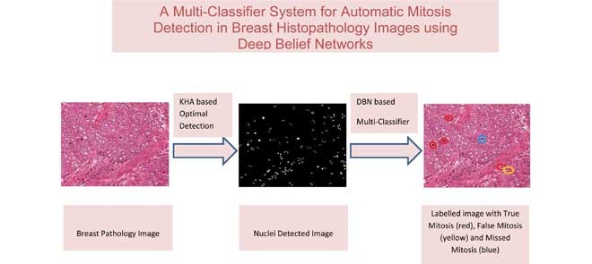
This paper presents a multi-classifier system for automatic mitosis detection in breast histopathology images using deep belief networks.
I. Introduction
Mitotic count is one of the most important prognostic factors in breast cancer [1] grading as it gives an assessment of the tumour proliferation. Usually, mitotic nuclei come out as hyper chromatic objects without a clear nuclear membrane in H & E stained breast histopathology images. Fig. 1 displays four main evolution phases in the mitosis, namely prophase, metaphase, anaphase, and telophase. The shape of nucleus is quite different in different phases, just as in the telophase a mitotic cell has two distinct nuclei. However, they need to be counted as one single mitosis since they are not separate cells. The detection process becomes time-consuming and extremely difficult due to large variety of shapes, size and low frequency of nuclei undergoing mitosis. In addition, irregular illumination, non-uniform stain variation, and presence of lymphocyte nuclei makes the detection process more challenging [2]. Currently, compared to conventional glass slides, Whole Slide Imaging (WSI) together with Computer-Aided Diagnosis (CAD) greatly improves the consistency and objectivity of histopathology analysis results [3]. The techniques already reported in the literature make use of hand crafted features which specifies morphology and intensity of mitotic nuclei. In such cases, accuracy of detection process is reduced due to large shape variation and indiscriminant nature of nuclei features. Though deep learning techniques provide good recall rate compared to other methods, training a CNN for a real world problem is very much computation intensive and GPU is become a necessity to speed up the training process [4]. Moreover, it demands huge samples of annotated images to learn massive number of parameters.
FIGURE 1.

Samples of cells in four mitotic phases. The images are snipped from the original image [5] acquired under 40X magnification.
The accuracy of mitotic evaluation depends up on specific nature of detection, segmentation and classification procedures employed in the processing framework [6]. This paper attempts to obtain better performance matrices, by careful design of algorithms at each stage starting from initial pre-processing to final classification stage. At the start of mitosis the chromosomes condense and the mitotic nucleus appears denser than the non-mitotic nucleus [7]. At the end of telophase, a furrow appears in the cell membrane which deepens and finally splits the cytoplasm into two, thus producing two new cells. But this changes can be manipulated as good features for classification only if the cells are precisely segmented. Hence, Localized Active Contour Model (LACM) [8] is used for segmentation of cells to exploit variation in cell size through the different phase of mitosis. Since the ACMs are susceptible to initial curve placement, an optimal multi thresholding technique based on Krill Herd Algorithm (KHA) [9] is utilized for initializing the nuclear region for accurate contour segmentation. The KHA exhibits superior performance in optimizing nuclei regions by fast convergence. Moreover, a Multi Classifier System (MCS) further improves the predictions from various individual classifiers. Though MCS has been applied for various applications [10], they are seldom used for mitotic detection.
The organization of the paper is in such a way that Section II gives a review of recent literature on mitosis detection. Section III presents an illustration of MCS. The proposed methodology in detail is conveyed in section IV. Experimental results are presented in section V followed by conclusion in section VI.
II. Literature Review
The earliest methods for mitosis detection were reported more than two decades ago in Feulgen stained breast cancer sections with a semi-automatic algorithm [11]. With the use of digital slides, a statistical approach was proposed in [12] which model mitotic regions by a Gamma distribution and non-mitotic regions by a Gaussian distribution. But it demands a context based tuning in the classification stage to reduce the number of false positives. In [13] Tek et al. have used an ensemble of Adaboost classifier after rough localization of cells with simple thresholding. The performance is affected by illumination and chromatic filters since it uses color based features. In [14], a graph-based multi-resolution algorithm is developed for mitosis extraction driven by unsupervised clustering of domain specific features. Ilastik software is used to segment candidate cells in [15]. Sertel et al. [16] proposed an algorithm to identify mitotic nuclei in neuro images based on probability based likelihood functions along with binary thresholding. Simple thresholding provides very poor detection due to diffusion of nuclei and background regions. Intensity, morphology, and texture features were utilized for the mitosis prediction in [17]. Irshad et al. [18] incorporated combination of texture and SIFT features for mitosis detection. The number of colour channels and redundant feature values result in poor classification performance. Moreover, the similarity in color and shape attributes of other nuclei are mistakenly recognized as mitoses by these features. S. Doyle et al. [19] utilized gabor features along with statistical and texture features for automatic grading of breast cancer. In [20], stain normalized R component is used for nuclei detection in breast pathology images. Veta et al. [21] segmented candidate objects by the level set method and reported a true positive rate of 59.5%. Fuzzy C-means (FCM) clustering algorithm is used to detect mitosis index in [22], which is very slow for large histopathology images. Hysteresis thresholding and morphological top-hat reconstruction is used for nuclei detection in neuro images [23] as well as in breast histology [24] images. This may detect almost all significant nuclei, but allows too many false positives. Recently Paul and Mukherjee [25] reported mitotic detection based on intensity features with an average F-score of 73%.
Multispectral imaging, also has been used to detect mitosis in breast histopathology images [26], [27]. Lu and Mandal [26] utilized linear discriminant analysis for spectral band selection. Bayesian modeling and local region thresholding is utilized to detect and segment the nuclei regions. Mitotic nuclei are detected by using a multi expert system with F-score of 47%. In [27] Irshad et al. selected the spectral bands with relatively higher Mutual Information (MI) for candidate detection. For each candidate in selected spectral bands, they compute morphological & multispectral statistical features for object classification. Wang et al. [28] performed initial segmentation of candidate objects by computing Laplacian of Gaussian (LOG) response of blue ratio images followed by local thresholding. Both CNN and handcrafted features were extracted for each candidate region and independent classifiers were trained using the two feature set. A third classifier, trained on the combination of handcrafted features and CNN based features classify the regions on which the two individual classifiers disagree. Weighted averages of all the classifier outputs provide the final prediction on mitotic cells.
In recent years mitotic detection is carried out with high level features provided by deep learning networks [3], [4], [29]. It requires a large number of labelled samples and parameters for training the network that further increases the computational complexity of the algorithm. Even though a number of works have been published, there is still progress to be made to achieve clinically acceptable results. Because of divergent inputs and inadequate samples in biomedical domain it is difficult to derive accurate detection procedures with usual pattern recognition techniques. Researchers are trying to reach highest quantitative results with hybrid techniques. In this paper, one such model is introduced, where the idea is to incorporate local information for detection, and segmentation techniques along with a multi-classifier system for accurate labelling of mitotic cells.
III. Multi Classifier System
The Multi Classifier System (MCS) is a potential way to upgrade the performance of various individual classifiers. It integrates different models by ensemble learning and provides improved predictive accuracy. According to Kuncheva [30] an effective MCS system is governed by the architecture, the fusion technique employed to combine the individual classifiers and accurate selection of diverse classifiers. The combination function should reflect the power of the individual classifiers, side step their limitations, and improve classification accuracy.
The architecture includes serial topology in which classifiers are applied in sequence and parallel topology, which involves parallel operation of multiple classifiers. However, research is focused on parallel architecture since MCS based on serial architecture is very specific to the particular application. In parallel architecture, a combination function merges the output of the individual classifiers. There are mainly two approaches for combining different individual classifiers: fixed rule and trained rule fusion [31]. The fixed rule strategy includes the product rule, sum rule, min rule, max rule, median rule, and majority voting. The trained rule strategy signifies the fusion as a classification problem and takes the outcomes of the individual classifiers as features to the fusion technique.
Let  be a set of classifiers and
  be the label set of
  classes as given in [10]. For a given feature vector
  , the outcome of the
  classifier is represented as
 |
where  is the grade provided by the classifier
  to the hypothesis that
  comes from the class
  . The classifier outcomes are arranged in a matrix as follows
 |
Matrix row represents classifier outcome  and column represents class j from classifiers
  . The combined output
  of the
  base classifiers is obtained as
 |
where  is the fusion rule. Among the fixed fusion technique majority voting is the easiest rule to design and implement.
1) Majority Voting (MV)
As per majority voting the classifier outcome is given by eqn.(3).
 |
To generate the final outcome, the grade chosen by more than half of the classifiers are selected. MV requires no prior training but is never optimal. Hence, to optimize the fusion process trained fusion strategy is utilized.
2) Trained Fusion Technique
In trained fusion technique, the fusion itself is regarded as a classification problem. The outputs of various classifiers are computed in vector form and given as input to the fusion technique. In Fig.2, consider  as the weights given to each classifier model in
  , and
, and  as their predictions. In order to build a powerful combination function, the weights given to the
  classifier models have to be adjusted. Objective function is formulated as
 |
subject to the constraints
 |
where  is the label for the observations. This paper proposes a fusion technique, which further decides the right combination of classifier weights using Deep Belief Network (DBN) based deep architecture.
FIGURE 2.

Schematic representation of trained fusion technique.
A. Deep Belief Networks
DBN is a learning model constructed by stacking more than one Restricted Boltzmann machines (RBMs) [33]. The greedy training approach is used to train the DBN, by training each of the RBMs, one layer at a time. Normally, back propagation is utilized to train neural networks with randomly initialized weights. During the training process all weights are updated from output layer to the input layer. The quality of weight updation is reduced by the vanishing gradient [34] problem. Hence, in order to initialize the weights, unsupervised pre-training is carried out by using Restricted Boltzmann machine (RBM) as discussed in the following subsection.
1). Restricted Boltzmann Machine
RBM contains only two identifiable layers, one visible layer and one hidden layer. No connection exists between nodes on the same layer that enables simultaneous updates of hidden and visible units. The visible and hidden units together has an energy function  as given in [32].
 |
where  and
and  represents binary state of visible unit
  and hidden unit
  , respectively.
  is the weight between units i and j. Similarly,
  is the
  bias attached with visible layer and
  is the
  bias attached with hidden layer. This energy is related to their probabilities as per eq. (8)
 |
For  visible units and
  hidden units,
 |
Similarly,
 |
Individual activation probabilities for hidden layer units can be expressed as
 |
Similarly, for visible layer units
 |
As first step of the algorithm, input is mapped to the visible layer of the first RBM. Then the RBM is trained using contrastive divergence method [33] as shown in Algorithm 1. After training, the weight matrix  is fixed for all the connections of first RBM. The second stack of RBM is attached over the previous stack by adding a new hidden layer. Then a new RBM machine is formed with hidden layer of previous RBM as input layer and repeats the same process of learning. After that a fine tuning process is applied to tune all the weights in the connection. The parameters
  = 0.1 and
  = 0.0001 are set by empirical estimation.
Algorithm 1 Training of RBM by Contrastive Divergence Method
-
1:
procedure :RBM Training
-
2:
Step 1. Set the state of the visible units with first sample of training data
-
3:
Step 2. Update all the hidden units in parallel by eq.11
-
4:
Step 3. Reconstruct the visible units by using eq.12
-
5:Step 4. Update weights using the following equation

-
6:
 positive
 =
= 
-
7:
 negative
 =
= 
-
8:
 is the learning rate
-
9:Step 5. Repeat steps 2 to 4 until required threshold accuracy
 is reached for all weights.
-
10:
Step 6. Repeat steps 1 to 5 with all samples from the training data.
-
11:
end procedure
IV. Methodology
The proposed method involves mainly two stages such as
-
•
Nuclei segmentation
-
•
MCS based nuclei classification
A. Nuclei Segmentation
Significant stain variations exist between tissue samples of the MITOS data set [5] and the clinical data set from RCC, Thiruvananthapuram. Hence, stain normalization is done as a pre-processing step before doing segmentation. An image with ideal stain characteristics is selected as a reference image for the stain normalization process. The algorithm modifies the RGB color distribution of the input image to that of the reference image by an image specific color deconvolution method [34]. A good contrast exists between the cell nuclei and other cell structures in the R component of the stain normalized image. Hence, it is selected for further processing after color space decomposition. Adaptive Wiener filtering [35] enhances the nuclei with feeble edges in the R component. Algorithm 2 presents major steps in the pre-processing stage. Precise segmentation may not achieve with the shattered nuclear membrane. Hence, Localized Active Contour Model (LACM) carries out segmentation of individual nuclei. Since the nuclear membrane starts to disappear in early stages of mitosis, nuclei and background regions diffuse each other, which makes it difficult to find a valid threshold for the detection of cell nuclei.
Algorithm 2 Pre-Processing
-
1:
procedure Stain Normalization [34]
-
2:
 where G is the RGB color space, Ĝ is the new color space and S is the stain matrix (absorption factors related with each stain used on the tissue).
-
3:
 the intensity of a pixel
  in the new color space
  and
and  is the optical density
-
4:
-
5:
(
 ,
,  ,
,  )
)  color component selection
 -
6:
 Wiener filtering
 -
7:
end procedure
The KHA based optimal thresholding provides a mask image, which specifies the centroids of the nuclei regions. Three threshold levels such as  ,
,  and
and  are selected to discriminate nuclei from cytoplasm, background stroma and vacuoles. The binary image,
  is obtained by quantising the lower threshold values into one and others to zero. Algorithm 3, given in appendix illustrates the key steps involved in the multi thresholding process based on Kapur’s entropy criteria [36] by mimicking motion characteristics of the krill individuals. The bi-level image
  serve as a mask which provides an initial contour to segment nuclei with their exact boundaries by Localised ACM segmentation. The LACM computes local energy along the nuclei neighborhood with a specific radius
  . Final segmentation is obtained by fixing the optimal energy points around the nuclear region. A detailed description of the LACM is given in appendix.
Algorithm 3 KHA Based Multi Thresholding
-
1:
procedure Krill Heard Algorithm
-
2:
KHA based multi thresholding
-
3:
Step 1. Parameter Initialization.
-
4:
Initialize the number of threshold values equal to the number of Krill individuals.
-
5:
Initialize KHA motion parameters & lower and upper boundaries of the threshold.
-
6:
Maximum number of iterations.
-
7:
Step 2. Position Calculation.
-
8:
Position of the krill individuals were set by the threshold values between 0 & 255.
-
9:
Step 3. Objective Function Evaluation
-
10:Fitness of current position is calculated using Kapur’s objective function as in [36]
where,
 are the optimal thresholds and
  are corresponding entropy values.
 -
11:Step 4. Update threshold values using position of the Krill individuals through the interval
 [9]
[9]
where,
 is the motion induced by the presence of other individuals,
  - Foraging activity and
  - Random diffusion.
 -
12:
Step 5. If maximum iterations reached, select the best thresholds and generate binary mask image
 .
. -
13:
Otherwise, repeat the process from Step 3.
-
14:
end procedure
B. Nuclei Classification
Classification phase mainly involves three stages such as
-
•
Feature computation
-
•
Feature selection
-
•
Decision fusion of individual classifiers using multi classifier frame work
1). Feature Computation
The different stages of mitosis exhibit significant variation in texture, size and shapes. Fig. 3(a) shows the example of an input image and Fig. 3(b) displays zoomed version of a selected LACM segmented region. Useful features that relate the size, shape and internal complexity of the cells are extracted from the segmented nucleus patch shown in Fig. 3(c). The intensity-based features include Median (M), Variance (V), Kurtosis (K) and Skewness (S). The features such as Area (A), Perimeter (P) and Solidity (SL) are the shape-based features considered along with fourteen Haralick texture features [37]. The algorithm computes texture features from the Gray Level Co-occurrence Matrix (GLCM) which describe how often pairs of a pixel with specific values occur in an image. However, the GLCM matrices can be estimated by taking any direction. Since adjacency occur in horizontal (0°), vertical (90°), along 45° & 135°, the texture features are computed typically along the four directions. By taking the average in all the four directions, fourteen texture features are computed that include Angular Second Moment (ASM), Contrast (C), Correlation (CR), Sum of Squares (SoS), Inverse Difference Moment (IDM), Sum Average (SA), Sum Variance (SV), Sum Entropy (SE), Entropy (E), Difference Variance (DV), Difference Entropy (DV), Information Measure of Correlation (IMoC) and Cluster Tendency (CT). For many nuclei, the CT takes considerable time for computation and the mean of SV equals zero. Hence, these two features are excluded in later stages of analysis. The final feature vector contains 31 features which include mean and range of the 12 texture features and 7 statistical features. With all computed features, classifier outcomes were very poor. Hence, a classifier subset evaluator finds best possible subsets among all the features.
FIGURE 3.

(a) Input Image, (b) Zoomed version of a selected patch of segmented nuclei region, (c) Nucleus patch.
2). Feature Selection
The classifier subset evaluator selects a small subset of features that give best discriminant information. In this technique, a greedy hill-climbing search [38] is performed in the feature space for possible feature subset. Each new subset is used to train a Random Forest (RF) classifier model, which is tested on a holdout set. For each subset, the algorithm computes a score based on the miscalculations made when tested on the holdout set. Finally, the algorithm stops when all the features are evaluated or when it achieves a certain limit of random forest runs. The subset of features with the highest score is selected as the best feature subset. Here the selected subset includes 20 features as shown in Table 1. The differences in the dynamic range of computed features are solved by normalizing the feature values within a uniform range. The normalized value  is given by eq. (13)
 |
where  is the actual feature value,
  and
and  represents minimum and maximum feature values, respectively. Fig.4 shows a box plot of the normalized feature set displaying the distribution of features for a set of 100 non-mitotic and mitotic nuclei. To show the discriminant nature of nuclei features, first 10 features are considered in the box plot.
TABLE 1. Selected Subset of Features Extracted From the Nuclei Regions.
| Feature Type | Feature Name | Dimension |
|---|---|---|
| Intensity-Based | Median, Variance, Kurtosis and Skewness | 4 |
| Shape-Based | Area (A), Perimeter (P) and Solidity (SL) | 3 |
| Texture-Based | Haralick features | 13 |
FIGURE 4.

Box Plot of the normalized feature set for non mitotic (blue) and mitotic nuclei (green).
3). Decision Fusion Using MCS
The Decision fusion consists of two stages. First, perform classification with four traditional classifiers and two ensemble classifiers separately. The traditional classifiers such as Neural Network (NN) [39], Decision Trees (DT) [40], Linear Discriminant (LD) [41] classifier, Nonlinear Support Vector Machine (NLSVM) [42] and ensemble classifiers like Robust Boost (RB) [43] and Random Forest (RF) [44] are used to train nuclei features. The learned models predict the probable class of detected nuclei in the test set. Several classifiers give equal sensitivity but variable precision values. In such cases, the proposed MCS combines the individual responses and train a second-stage classifier, which provides improved detection performance by regularizing the weights of initial classifiers.
V. Experimental Results and Discussion
A. Data Set
The proposed technique uses the MITOS dataset [5] and the clinical data set from Regional Cancer (RCC), Thiruvananthapuram, India, for evaluation. The MITOS dataset includes high power field (HPF) images of breast tissue scanned at 40X magnification by Aperio (AP) and Hamamatsu (HM) scanners, with a resolution of  per pixel. Location of mitotic nuclei are marked by senior pathologists and provided along with the dataset. H & E stained breast biopsy samples of three specimens from RCC are also used for clinical evaluation. They are taken through Leica digital image acquisition system attached with the microscope. All images in the MITOS data set (MD) are of
  size and that of clinical data (CD) are of
  size. An experienced pathologist manually assessed mitotic nuclei in clinical images. Out of 242 HPF images (399 mitosis), 170 images (278 mitosis) are used for training, remaining 72 HPF images (121 mitosis) are used for testing. Since mitotic nuclei are less in number, selective sampling of non-mitotic nuclei and random up sampling of mitotic nuclei are carried out to reduce the skewness of data. Training set is prepared with 800 mitosis and 3075 non-mitosis. Test set consist of 105 mitosis and 1000 non-mitosis from MITOS data set and 16 mitosis and 268 non-mitosis from the clinical data set, respectively. The experiments are simulated by using Matlab 2016 environment.
B. Performance Measures
A detected mitosis is counted as correct detection if it is located within a range of  from the centroid of a ground truth mitosis [45]. The well-known validation measures such as Sensitivity, Precision and F-score as given in eq. (14)–(16) are used to assess the detection process by comparing with manual detection done by the pathologists.
 |
where  represents number of True Positives (TP-correctly detected Mitosis),
  number of False Positives (FP- wrongly detected Mitosis) and
  number of False Negatives (FN- missed mitosis). We compare the proposed method with recently reported approaches in [4] and [25].
C. Segmentation
The stain normalization improves the contrast between cell nuclei and other cell structures. Fig. 5 displays sample images with stain variation from original data set and corresponding normalized images along with the reference image. Three threshold levels such as T1, T2 and T3 provided by KHA based optimal detection discriminates cell nuclei from other cell structures. This image act as a mask for initial curve placement in the LACM segmentation. Fig. 6. (a) & (b) shows example of an original image and corresponding labelled nuclei by the LACM technique. In Fig. 6. (c) & (d) green contour denotes the segmented region boundary realized by the proposed technique, which is very close to the manually labelled one as shown in doted blue contour. The technique reported a segmentation accuracy of 93.79% with a Maximum Absolute Distance (MAD) of 1.05 [46].
FIGURE 5.

(a1), (a2) Sample images from Mitos data set and RCC data set with stain variation, (b1) & (b2) Reference image, (c1) & (c2) Stain normalized images.
FIGURE 6.

Visual results of Segmentation. (a) Original image, (b) Labelled nuclei by LACM segmentation, (c) & (d) Samples of the segmented nuclear boundary (shown in Green contour) compared to manually labelled nuclear boundary (Blue contour).
D. Classification
The proposed framework results in 100% accuracy in 5-fold cross validation using the training sets. The trained classifiers detect new unknown instances of mitotic and non-mitotic classes from the evaluation set. With all computed features, nonlinear SVM and Random Forest classifiers perform better in terms of less number of False Positives (FP), but with less number of True Positives (TP) as well. When selected subset of features has used all classifiers offer better TP values and result in a high value of F-score. The nonlinear SVM uses the quadratic kernel and Sequential Minimal Optimization (SMO) algorithm to map the training data into higher dimensional kernel space. The RF classifier generates a group of 500 trees that inspect  random features, (
 - the number of features) for training. Table 2 presents classification performance of nonlinear SVM and RF classifier with all the computed features and selected subset of features. Table 3 shows the performance of all other selected classifiers on MITOS dataset.
TABLE 2. Performance of NLSVM and RF Classifier.
| Classifier | Features |  |
 |
 |
 |
Sensitivity | Precision | F-score |
|---|---|---|---|---|---|---|---|---|
| NLSVM | All Features | 79 | 43 | 206 | 26 | 75.24 | 64.75 | 69.6 |
| Selected Features | 94 | 46 | 203 | 11 | 89.52 | 67.14 | 76.73 | |
| RF | All Features | 65 | 28 | 221 | 40 | 61.9 | 69.89 | 65.65 |
| Selected Features | 98 | 32 | 217 | 7 | 93.33 | 75.38 | 83.4 |
TABLE 3. Performance by Individual Classifiers.
| Classifier |  |
 |
Sensitivity | Precision | F-Score |
|---|---|---|---|---|---|
| Discriminant Analysis | 97 | 51 | 92.38 | 65.54 | 76.67 |
| Robust Boost | 97 | 62 | 92.38 | 61.01 | 73.48 |
| Neural Network | 94 | 56 | 89.52 | 62.66 | 73.72 |
| Decision Trees | 99 | 66 | 94.28 | 60 | 73.33 |
| Random Forest | 97 | 36 | 92.38 | 72.93 | 81.51 |
At first, majority voting takes all individual classifier outcomes together but results in poor detection performance. When classifiers such as RF, DT, NLSVM and LD classifiers are combined, results are close to the best classifier, RF. The same combination is selected for DBN based MCS (DBN-MCS) which outperformed the voting rule in all trials. Fig. 7 shows comparison of the proposed MCS based classification as well as majority voting based classification on MITOS data set. The DBN architecture uses the learning rate as 0.2 and number of hidden layers as five. When DBN-MCS is used, there is a substantial improvement in sensitivity compared to precision, which is preferred in biomedical applications. In Fig.8, (a1) and (a2) shows the original images from clinical data and MITOS data set, respectively. Fig.8 (b1), (b2) displays the mask image given by the KHA based multi-thresholding and c1, c2 show rightly detected mitotic nuclei (TP) in red circles. One nucleus in the blue circle shows the missed mitotic nuclei (FN) and nuclei shown in yellow circles represents false mitosis (FP). The missed mitosis looks small and is very similar to lymphocytes. Table. 4 shows enhanced sensitivity and precision obtained with clinical images by the proposed DBN based MCS. Since Mitotic nuclei are very less compared to normal nuclei in clinical images, there is skewness in the test data. MV based MCS also shows increased performance in clinical data. Hence, MCS is a superior technique for improving the performance of individual classifiers.
FIGURE 7.

Comparative results by the proposed MCS and the classifier RF.
FIGURE 8.

Visual results. (a1), (a2) Original image from clinical and MITOSIS data set, (b1), (b2) Initial contour provided by KHA, (c1), (c2) Classification results (nuclei shown in Red circles: TP, Yellow circles: FP, Blue circles: FN).
TABLE 4. Performance of the Proposed MCS and the Classifier RF on the Clinical Dataset.
| Classifier |  |
 |
Sensitivity | Precision | F-Score |
|---|---|---|---|---|---|
| RandomForest | 11 | 10 | 68.75 | 52.38 | 59.46 |
| Majority Voting | 11 | 9 | 68.75 | 55 | 61.11 |
| DBN-MCS | 15 | 9 | 93.75 | 62.50 | 75.0 |
Fig. 9 shows comparison of the proposed technique with two recently reported techniques in the literature. The sensitivity rate is low for the two techniques considered. All the experiments in this work provide better results compared to the detection results reported by Chen et al. [4], and Paul and Mukherjee [25] who have implemented their algorithm using the same MITOS data set. Use of LACM based optimal segmentation provides accurate labelling of nuclei regions and results in substantial improvement of all the classifiers used in the algorithm. Moreover, careful computation of the Haralick features and selection of feature subset also contribute to the detection performance. Finally, the combination of different classifiers by DBN MCS further enhances the sensitivity of the algorithm, which can assists the pathologist in biopsy analysis.
FIGURE 9.

VI. Conclusion
The paper proposes an effective and accurate framework to carry out segmentation and classification of mitotic nuclei in breast histopathology images. Since mitosis are generally rare and seen well separated, they are very hard to discriminate from non-mitotic nuclei. The proposed technique first utilizes stain normalization process to reduce the complexity in segmenting exact nuclei boundary in large clinical images. The difficulty in segmenting exact nuclei boundary is treated in an optimal way by the KHA based LACM. A multi classifier based on deep belief network is utilized to detect mitotic candidates from the contour segmented nuclei regions. Sequential feature selection and feature normalization also aid in enhancing the individual classifier outcomes. The DBN-MCS significantly improves the sensitivity score compared to majority voting based MCS, by optimizing the weights of individual classifiers during the training period. The proposed technique is evaluated on a publicly available standard dataset and also on a clinical data set obtained from a premier cancer research institute, Regional Cancer Centre (RCC), Thiruvananthapuram, India. Senior pathologists verified the results obtained by the proposed technique on both data sets. Compared to the existing techniques, the proposed framework results in better performance with high sensitivity make it more realistic in clinical applications. Future analyses aim to improve the precision of the detection process by including more discriminant features extracted by deep architectures and subsequent classification with GPU optimization.
Acknowledgement
The authors acknowledge the support rendered for this work by RCC Thiruvananthapuram, India. The authors also thank Dr. Sujathan, Dr. Jayasree, Dr.Abitha and Dr.Anju for their timely guidance and help in the evaluation process.
Biographies

K. Sabeena Beevi received the B.Tech. degree in electrical and electronics engineering from the College of Engineering Trivandrum, Kerala, India, in 1997, and the M.Tech. degree in computer science, with specialization in digital image computing, from the Department of Computer Science, University of Kerala, Thiruvananthapuram, India, in 2009, where she is currently pursuing the Ph.D. degree. She is currently an Assistant Professor of Electrical and Electronics Engineering with the Thangal Kunju Musaliar College of Engineering, Kollam, India. Her research interests include pattern recognition, machine learning, medical image analysis, and computer vision.

Madhu S. Nair received the B.C.A. and M.C.A. degrees (Hons.) from Mahatma Gandhi University in 2000 and 2003, respectively, the M.Tech. degree (Hons.) in computer science, with specialization in digital image computing, from the University of Kerala in 2008, and the Ph.D. degree in computer science (image processing) from Mahatma Gandhi University in 2013. He has authored around 72 research papers in reputed International Journals and Conference Proceedings published by the IEEE, Springer, Elsevier, Wiley, and IOS Press. His research interests include digital image processing, pattern recognition, computer vision, data compression, and soft computing. He is a member of the ACM, an Associate Life Member of the Computer Society of India, and a member of the International Association of Engineers. He is serving as a Reviewer for around 40 International Journals published by the IEEE, Elsevier, Springer, and Wiley. He also served as a Technical Program Committee Member/Reviewer for several reputed International Conferences. He is currently an Associate Editor of the prestigious IEEE Access Journal and also the Editorial Board Member of the International Arab Journal of Information Technology.

G. R. Bindu received the Ph.D. degree from the University of Kerala, India, in 2006. She is currently a Professor of Electrical Engineering with the College of Engineering Trivandrum (CET), Thiruvananthapuram, Kerala, India. She has served as an Engineer with Kerafed and as a Faculty Member in various engineering colleges. She has guided several master’s and Ph.D. level dissertations. She serves as an Evaluator of Ph.D. thesis for various Indian universities. She has a number of research publications to her credit, including in the prestigious IEEE Transactions. Her current research interests are digital signal processing, electromagnetic field theory, the control and condition monitoring of electric drives.
Appendix A. Localised Active Contour Model
For a curve  , the level set function,
  , satisfies the following conditions as given in [47]
 , if (x,y) is inside the curve
 , if (x,y) is outside the curve
where  and
and  are spatial variables representing a single point in the image. The zero level of
  is taken as the contour as given in eq. (17)
 |
A characteristic function,  , is used to identify local regions in terms of a radius parameter
  .
.
 |
Based on the localization radius  , a window N of size 2r X 2r is selected for each pixel in the initial contour. LACM computes local energy as local interior and local exterior energy along the nuclei neighborhood. The energy functional
  for the curve
  , can be written as
 |
where  is curvature of the closed curve
  and
and  is a positive fixed parameter which determines the smoothness of the contour. Local energies are computed by splitting the local neighborhoods
  into local interior and local exterior by the evolving contour as given in [48].
 |
where,  and
and  are average intensity value inside and outside the object region. If
  and
and  are areas of the regions inside and outside
  , respectively, the gradient of external force
  is expressed as
 |
The optimal energy points around the nulear region in time  is given by eq. (23)
 |
Appendix B. KHA Based Multi Thresholding Algorithm
References
- [1].Elston E. W. and Ellis I. O., “Method for grading breast cancer,” J. Clin. Pathol., vol. 46, no. 2, pp. 189–190, 1993. [DOI] [PMC free article] [PubMed] [Google Scholar]
- [2].Dundar M. M., et al. , “Computerized classification of intraductal breast lesions using histopathological images,” IEEE Trans. Biomed. Eng., vol. 58, no. 7, pp. 1977–1984, Jul. 2011. [DOI] [PMC free article] [PubMed] [Google Scholar]
- [3].Malon C. D. and Cosatto E., “Classification of mitotic figures with convolutional neural networks and seeded blob features,” J. Pathol. Inform., vol. 4, no. 1, p. 9, 2013. [DOI] [PMC free article] [PubMed] [Google Scholar]
- [4].Chen H., Dou Q., Wang X., Qin J., and Heng P. A., “Mitosis detection in breast cancer histology images via deep cascaded networks,” in Proc. 13th AAAI Conf. Artif. Intell., 2016, pp. 1160–1166. [Google Scholar]
- [5].(2014). MITOS, ICPR 2014 Contest, IPAL UMI CNRS Lab Std. [Online]. Available: http://ipal.cnrs.fr/ICPR2014 [Google Scholar]
- [6].Roux L., et al. , “Mitosis detection in breast cancer histological images An ICPR 2012 contest,” J. Pathol. Inform., vol. 4, no. 1, p. 8, 2013. [DOI] [PMC free article] [PubMed] [Google Scholar]
- [7].Barlow P. W., “Changes in chromatin structure during the mitotic cycle,” Protoplasma, vol. 91, no. 2, pp. 207–211, Jun. 1977. [DOI] [PubMed] [Google Scholar]
- [8].Lankton S. and Tannenbaum A., “Localizing region-based active contours,” IEEE Trans. Image Process., vol. 17, no. 11, pp. 2029–2039, Nov. 2008. [DOI] [PMC free article] [PubMed] [Google Scholar]
- [9].Gandomi A. H. and Alavi A. H., “Krill herd: A new bio-inspired optimization algorithm,” Commun. Nonlinear Sci. Numer. Simul., vol. 17, no. 12, pp. 4831–4845, Dec. 2012. [Google Scholar]
- [10].Buxton B. F., Langdon W. B., and Barrett B. J., “Data fusion by intelligent classifier combination,” Meas. Control-London Inst. Meas. Control, vol. 34, no. 8, pp. 229–234, Oct. 2001. [Google Scholar]
- [11].Beliën J. A. M., Baak J. P. A., van Diest P. J., and Van Ginkel A. H. M., “Counting mitoses by image processing in Feulgen stained breast cancer sections: The influence of resolution,” Cytometry A, vol. 28, no. 2, pp. 135–140, Jun. 1997. [PubMed] [Google Scholar]
- [12].Khan A. M., El-Daly H., and Rajpoot N. M., “A Gamma-Gaussian mixture model for detection of mitotic cells in breast cancer histopathology images,” in Proc. 21st Int. Conf. Pattern Recognit. (ICPR), Nov. 2012, pp. 149–152. [Google Scholar]
- [13].Tek F. B., et al. , “Mitosis detection using generic features and an ensemble of cascade adaboosts,” J. Pathol. Inform., vol. 4, no. 1, p. 12, 2013. [DOI] [PMC free article] [PubMed] [Google Scholar]
- [14].Roullier V., Lézoray O., Ta V.-T., and Elmoataz A., “Multi-resolution graph-based analysis of histopathological whole slide images: Application to mitotic cell extraction and visualization,” Comput. Med. Imag. Graph., vol. 35, nos. 7–8, pp. 603–615, Oct-Dec 2011. [DOI] [PubMed] [Google Scholar]
- [15].Sommer C., Fiaschi L., Hamprecht F. A., and Gerlich D. W., “Learning-based mitotic cell detection in histopathological images,” in Proc. 21st Int. Conf. Pattern Recognit. (ICPR), Nov. 2012, pp. 2306–2309. [Google Scholar]
- [16].Sertel O., Catalyurek U. V., and Gurcan M. N., “Computer-aided prognosis of neuroblastoma: Detection of mitosis and karyorrhexis cells in digitized histological images,” in Proc. Int. Conf. IEEE Eng. Med. Biol. Soc. (EMBC), Sep. 2009, pp. 1433–1436. [DOI] [PubMed] [Google Scholar]
- [17].Beevi K. S., Nair M. S., and Bindu G. R., “Detection of mitotic nuclei in breast histopathology images using localized ACM and random kitchen sink based classifier,” in Proc. IEEE 38th Annu. Int. Conf. Eng. Med. Biol. Soc. (EMBC), Aug. 2016, pp. 2435–2439. [DOI] [PubMed] [Google Scholar]
- [18].Irshad H., et al. , “Automated mitosis detection using texture, SIFT features and HMAX biologically inspired approach,” J. Pathol. Inform., vol. 4, no. 2, p. 12, 2013. [DOI] [PMC free article] [PubMed] [Google Scholar]
- [19].Doyle S., Agner S., Madabhushi A., Feldman M., and Tomaszewski J., “Automated grading of breast cancer histopathology using spectral clustering with textural and architectural image features,” in Proc. 5th IEEE Int. Symp. Biomed. Imag., Nano Macro (ISBI), May 2008, pp. 496–499. [Google Scholar]
- [20].Beevi K. S. and Bindu G. R., “Analysis of nuclei detection with stain normalization in histopathology images,” Indian J. Sci. Technol., vol. 8, no. 23, Sep. 2015, pp. 547–551. [Google Scholar]
- [21].Veta M., van Diest P. J., and Pluim J. P. W., “Detecting mitotic figures in breast cancer histopathology images,” Proc. SPIE, vol. 8676, pp. 867607-1–867607-7, Mar. 2013. [Google Scholar]
- [22].Anari V., Mahzouni P., and Amirfattahi R., “Computer-aided detection of proliferative cells and mitosis index in immunohistichemically images of meningioma,” in Proc. 6th Iranian Conf. Mach. Vis. Image Process., Oct. 2010, pp. 1–5. [Google Scholar]
- [23].Gurcan M. N., Pan T., Shimada H., and Saltz J., “Image analysis for neuroblastoma classification: Segmentation of cell nuclei,” in Proc. 28th Annu. Int. Conf. IEEE Eng. Med. Biol. Soc. (EMBS), Aug./Sep. 2006, pp. 4844–4847. [DOI] [PubMed] [Google Scholar]
- [24].Beevi S., Nair M. S., and Bindu G. R., “Automatic segmentation and classification of mitotic cell nuclei in histopathology images based on active contour model,” in Proc. Int. Conf. Contemp. Comput. Inform. (IC3I), Nov. 2014, pp. 740–744. [Google Scholar]
- [25].Paul A. and Mukherjee D. P., “Mitosis detection for invasive breast cancer grading in histopathological images,” IEEE Trans. Image Process., vol. 24, no. 11, pp. 4041–4054, Nov. 2015. [DOI] [PubMed] [Google Scholar]
- [26].Lu C. and Mandal M., “Toward automatic mitotic cell detection and segmentation in multispectral histopathological images,” IEEE J. Biomed. Health Inform., vol. 18, no. 2, pp. 594–605, Mar. 2014. [DOI] [PubMed] [Google Scholar]
- [27].Irshad H., Gouaillard A., Roux L., and Racoceanu D., “Multispectral band selection and spatial characterization: Application to mitosis detection in breast cancer histopathology,” Comput. Med. Imag. Graph., vol. 38, no. 5, pp. 390–402, Jul. 2014. [DOI] [PubMed] [Google Scholar]
- [28].Wang H., et al. , “Cascaded ensemble of convolutional neural networks and handcrafted features for mitosis detection,” J. Med. Imag., vol. 1, no. 3, p. 90410B, Mar. 2014. [DOI] [PMC free article] [PubMed] [Google Scholar]
- [29].Cireşan D. C., Giusti A., Gambardella L. M., and Schmidhuber J., “Mitosis detection in breast cancer histology images with deep neural networks,” in Proc. Int. Conf. Med. Image Comput. Comput.-Assist. Intervent., 2013, pp. 411–418. [DOI] [PubMed] [Google Scholar]
- [30].Kuncheva L. I., Bezdek J. C., and Duin R. P. W., “Decision templates for multiple classifier fusion: An experimental comparison,” Pattern Recognit., vol. 34, no. 2, pp. 299–314, Feb. 2001. [Google Scholar]
- [31].Kittler J., Hatef M., Duin R. P. W., and Matas J., “On combining classifiers,” IEEE Trans. Pattern Anal. Mach. Intell., vol. 20, no. 3, pp. 226–239, Mar. 1998. [Google Scholar]
- [32].Hinton G., “A practical guide to training restricted Boltzmann machines,” Momentum, vol. 9, no. 1, p. 926, 2010. [Google Scholar]
- [33].Bengio Y., Lamblin P., Popovici D., and Larochelle H., “Greedy layer-wise training of deep networks,” in Advances in Neural Information Processing Systems, vol. 19 Cambridge, MA, USA: MIT Press, 2007, p. 153. [Google Scholar]
- [34].Khan A. M., Rajpoot N., Treanor D., and Magee D., “A nonlinear mapping approach to stain normalization in digital histopathology images using image-specific color deconvolution,” IEEE Trans. Biomed. Eng., vol. 61, no. 6, pp. 1729–1738, Jun. 2014. [DOI] [PubMed] [Google Scholar]
- [35].Haykin S. and Widrow B., Eds., Least-Mean-Square Adaptive Filters, vol. 31 Hoboken, NJ, USA: Wiley, 2003. [Google Scholar]
- [36].Sahoo P. K., Soltani S., and Wong A. K. C., “A survey of thresholding techniques,” Comput. Vis., Graph., Image Process., vol. 41, no. 2, pp. 233–260, Feb. 1988. [Google Scholar]
- [37].Haralick R. M., Shanmugam K., and Dinstein I., “Textural features for image classification,” IEEE Trans. Syst., Man, Cybern., vol. SMC-3, no. 6, pp. 610–621, Nov. 1973. [Google Scholar]
- [38].Blum A. L. and Langley P., “Selection of relevant features and examples in machine learning,” Artif. Intell., vol. 97, pp. 245–271, Dec. 1997. [Google Scholar]
- [39].Cho S.-B., “Neural-network classifiers for recognizing totally unconstrained handwritten numerals,” IEEE Trans. Neural Netw., vol. 8, no. 1, pp. 43–53, Jan. 1997. [DOI] [PubMed] [Google Scholar]
- [40].Swain P. H. and Hauska H., “The decision tree classifier: Design and potential,” IEEE Trans. Geosci. Electron., vol. 15, no. 3, pp. 142–147, Jul. 1977. [Google Scholar]
- [41].Liu C. and Wechsler H., “Gabor feature based classification using the enhanced Fisher linear discriminant model for face recognition,” IEEE Trans. Image Process., vol. 11, no. 4, pp. 467–476, Apr. 2002. [DOI] [PubMed] [Google Scholar]
- [42].Lu S.-X. and Wang X.-Z., “A comparison among four SVM classification methods: LSVM, NLSVM, SSVM and NSVM,” in Proc. Int. Conf. Mach. Learn. Cybern., vol. 7 Aug. 2004, pp. 4277–4282. [Google Scholar]
- [43].Dietterich T. G., “Ensemble methods in machine learning,” in Proc. Int. Workshop Multiple Classifier Syst., 2000, pp. 1–15. [Google Scholar]
- [44].Liaw A. and Wiener M., “Classification and regression by randomforest,” R News, vol. 2, no. 3, pp. 18–22, 2002. [Google Scholar]
- [45].Roux L., et al. , “Mitos & atypia,” Image Pervasive Access Lab (IPAL), Agency Sci, Technol. & Res. Inst. Infocom Res, Singapore, Tech. Rep.1, 2014. [Google Scholar]
- [46].Beevi S. Nair K, M. S., and Bindu G. R., “Automatic segmentation of cell nuclei using Krill Herd optimization based multi-thresholding and localized active contour model,” Biocybern. Biomed. Eng., vol. 36, no. 4, pp. 584–596, 2016. [Google Scholar]
- [47].Soman K. P. and Ramanathan R., Digital Signal and Image Processing—The Sparse Way. New Delhi, India: ISA Publication, 2012. [Google Scholar]
- [48].Yezzi A. Jr., Tsai A., and Willsky A., “A fully global approach to image segmentation via coupled curve evolution equations,” J. Vis. Commun. Image Represent., vol. 13, nos. 1–2, pp. 195–216, Mar. 2002. [Google Scholar]