Abstract
Temporal focusing (TF) microscopy is a wide-field two-photon excitation fluorescence (2PEF) microscopy technique, the optical sectioning capability of which is lower than that of point-scanning 2PEF microscopy. Here we demonstrate TF microscopy using three-photon excitation fluorescence (3PEF), which enhances the optical sectioning capability. As an excitation light source for the 3PEF, we developed an Yb-fiber chirped pulse amplifier, which produces 92-fs 9.0-μJ 1060-nm pulses at a repetition rate of 200 kHz. The optical sectioning capability was improved by a factor of 1.3 compared with that of 2PEF-TF microscopy. We also demonstrate dual-color imaging with both 2PEF and 3PEF.
OCIS codes: (180.4315) Nonlinear microscopy; (140.3510) Lasers, fiber
1. Introduction
Temporal focusing (TF) microscopy is a wide-field two-photon excitation fluorescence (2PEF) microscopy technique that is capable of optical sectioning [1,2]. The observation of a large field of view with TF microscopy requires high excitation power, and excitation with a high average power may induce sample heating. This problem can be solved by utilizing an amplifier that produces pulses with high peak power and ultrashort pulse duration at a low repetition rate (< 1 MHz) as the excitation light source. Because TF microscopy does not require laser scanning, even repetition rates of 10 kHz are sufficient for video-rate imaging. Recently, TF microscopies using amplified pulses with a low average power have been employed to obtain a large field of view (5000–20000 μm2) in 2PEF video-rate imaging [3,4]. However, because the optical sectioning capability of 2PEF-TF microscopy is lower than that of point-scanning 2PEF microscopy, the background fluorescence generated at out-of-focus regions is larger for 2PEF-TF microscopy compared with that for point-scanning 2PEF microscopy. TF microscopy can be combined with structured illumination microscopy to reject the out-of-focus background fluorescence, which is eliminated by post-processing after the data acquisition [5,6]. Nevertheless, because the background fluorescence still enters the detector, it limits the dynamic range of the detector. The use of line illumination by combining TF and spatial focusing provides an axial resolution equivalent to that of point-scanning 2PEF microscopy [7], but the line illumination must be mechanically scanned to get the full two-dimensional field. Thus, to shorten the image acquisition time, the pulse repetition rate of more than tens of megahertz is required. The time multiplexing technique [8,9] can be used to suppress the out-of-focus excitation in TF microscopy, but it requires a complex setup [10,11]. Here, we demonstrate a simple way to reduce the excitation volume along the axial direction by utilizing three-photon excitation fluorescence (3PEF) with TF microscopy (3PEF-TF). The cubic dependence of the 3PEF signal on the excitation intensity allows the excitation volume in TF microscopy to be further confined in a similar manner to point-scanning 3PEF microscopy [12]. Third harmonic generation, the intensity of which is proportional to the cubic of the excitation intensity, has been applied to TF microscopy with line illumination [13]. However, to our knowledge, there have been no reports of 3PEF-TF microscopy thus far.
The excitation light source used in 3PEF-TF must meet several requirements. To induce three-photon excitation, a high-power laser must be used because three-photon excitation cross-sections are on the order of 10−83 cm6(s/photon)2, which is much smaller than the typical two-photon excitation cross-sections of 10−49 cm4s/photon [14]. Ultrashort pulses around 100 fs are suitable for TF microscopy [1]. This is because the magnification telescope, which is used to image the dispersive grating in the sample, must be large for long pulses, and the bandwidth of overly short pulses may exceed the absorption bandwidth of the fluorophore and suffers from significant material dispersion. Low repetition rate systems avoid photobleaching related to triplet state formation because the pulse period, which is longer than the triplet-state lifetime of fluorophores, enables the molecule to relax back to the ground state before the next pulse arrives [15]. The repetition rate of a few hundred kHz is often suitable because the triplet-state lifetime of most fluorophores including green fluorescence protein and Rhodamine dye is a few μs [15,16]. Due to the low repetition rate, the pulse energy must be on the order of a few μJ to provide sufficient fluorescence intensity. If the repetition rate is too low, a higher peak intensity may exceed the damage threshold of biological samples. The ablative damage threshold for biological tissues ranges from 1.5 to 2.2 J/cm2 in the wavelength region of from 800 nm to 1450 nm [17]. High average power is also required in TF microscopy. Since the lowest optical absorption band between 400 and 2400 nm in a biological tissue is the 1050–1100 nm region [18], pulses in this spectral region are desirable to avoid sample heating. In this paper, we report on the development of an Yb-fiber CPA system for 3PEF-TF microscopy that produces 92-fs pulses with an energy of 9.0 μJ at a repetition rate of 200 kHz and a center wavelength of 1060 nm. Output of commercial optical parametric amplifiers (OPAs) are close to those of our fiber laser system. However, fiber laser systems have a big advantage of very compact and excellent stability compared with the OPA systems.
An Yb-fiber chirped pulse amplifier (CPA), provides gain in the 1050–1100 nm region and a broad fluorescence bandwidth [19]. In order to generate 100-fs pulses with an energy on the order of a few μJ, we must manage the nonlinear phase shift accumulated in the Yb-fiber CPA amplifier system. The nonlinear phase shift can be minimized by increasing the core diameter of the gain fiber. By using an Yb-doped rod fiber with a core diameter of 400 μm, an Yb-fiber CPA producing 270-fs pulses with an energy of 100 μJ has been reported [20]. Even at a gain of 23 dB, the pulse duration has been limited to 120 fs due to the gain-narrowing effect during amplification in the linear regime, in which the nonlinear phase shift is less than 1 rad [21]. By compensating for gain narrowing using multiple dielectric layers, 65-fs pulses with an energy of 100 nJ at a gain of 21 dB have been generated [22]. Shorter pulses have been generated through nonlinear amplification by the interplay of gain narrowing and spectral broadening by self-phase modulation [23]. Although the distortion of the spectral phase can be compensated by the use of a 4-f pulse shaper [24], the compensable distortion is limited by the spectral resolution of the shaper. Thus, it is difficult to perfectly compensate the spectral phase of the broadened pulse of which spectrum is broadened by strong self-phase modulation. However, Fourier transform-limited (FTL) pulses are required in TF microscopy because spectral phase distortion results in degradation of the optical sectioning capability.
In this study, by compensating for gain narrowing using a long-pass filter and for higher-order dispersion using a 4-f pulse shaper [24], an FTL pulse duration of 92 fs is obtained at a gain of 48 dB. Using this Yb-fiber laser system, we demonstrate 3PEF-TF microscopy as well as dual-color imaging of a blue fluorophore and a red fluorophore. The significantly different excited-state energies of two different fluorescence species can be simultaneously accessed by two-photon excitation and three-photon excitation using a single wavelength of 1060 nm. In general, the emission spectra of the two fluorophores are also significantly different. Thus, dual-color imaging can be achieved by a combination of two-photon excitation and three-photon excitation. In Sect. 2, we introduce and characterize the experimental setup for our Yb-fiber CPA system. In Sect. 3, we describe our experimental setup for TF microscopy using the custom-built Yb-fiber CPA system and report imaging results. In Sect. 4, we summarize the paper.
2. Yb-fiber CPA
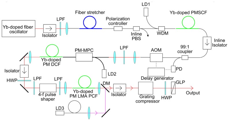
Figure 1 shows a schematic diagram of the Yb-fiber chirped-pulse amplifier (CPA) system. A custom-built 45-Mhz Yb-fiber oscillator, which is similar to a typical mode-locked Yb-fiber laser based on nonlinear polarization rotation [25], was employed as the seed source in the CPA system. The 0.24-nJ (11-mW average power) seed pulses were stretched using a fiber stretcher with a group delay dispersion (GDD) of 7.5 ps2 and a third-order dispersion (TOD) of –0.087 ps3. The stretched pulses were amplified to 4.1 nJ (185-mW average power) by a single-mode Yb-fiber amplifier with a core diameter of 6 μm and a length of 75 cm, which was forward pumped through a wavelength-division multiplexer (WDM) by a single-mode fiber-coupled, wavelength-stabilized laser diode (LD) with a wavelength of 976 nm. Around 1% of the output power from the first amplifier was picked off and sent to a fast photodiode (PD). The output from the PD was sent into a delay generator (Stanford Research Systems, DG645), which was used to drive an acousto-optic modulator (AOM) used to reduce the repetition rate from 45 MHz to 200 kHz. The AOM was placed after the first amplifierbecause amplified spontaneous emission (ASE) in the fiber amplifier increases as the input seed power decreases. The output pulses from the AOM were amplified to 600 nJ (120-mW average power) using a 1.5-m-long Yb-doped double-clad (DC) fiber with a core diameter of 10 μm and a cladding diameter of 125 μm, which was forward pumped through a multimode power combiner (MPC) by a multimode fiber-coupled, wavelength-stabilized laser diode (LD) with a wavelength of 976 nm. The output pulses from the second amplifier were passed through a 4-f pulse shaper with a liquid-crystal spatial light modulator (LC-SLM). To further increase the pulse energy, we used a 1.8-m-long Yb-doped large-mode-area (LMA) photonic crystal fiber (PCF) amplifier with a core diameter of 40 μm and a cladding diameter of 200 μm, which was counter-pumped by a wavelength-stabilized LD with a wavelength of 976 nm. When the pumping power was 10 W, a pulse energy of 13.5 μJ (2.7-W average power) was obtained after the isolator. Since spatiotemporal coupling induced by the 4-f pulse shaper affects on the spatial beam profile [26], the spatial filtering within the fiber in the third amplifier placed after the shaper was also utilized for cleaning up the beam profile. The other reason for placing the 4-f pulse shaper before the third amplifier is that the output power from the third amplifier can increase in excess of the damage threshold of the LC-SLM, which limits the output power from the second amplifier. In a quasi-three-level fiber amplifier, the ASE noise for backward pumping is higher than that for forward pumping, while a power conversion efficiency for backward pumping is higher than that for forward pumping [27]. Thus, the first and second amplifiers in which the input seed powers are low were forward pumped, while the third amplifier with sufficient seed input power was backward pumped. The amplified pulse was compressed by the combined use of the 4-f pulse shaper and a grating compressor with a pair of 1600-lines/mm transmission gratings. The grating compressor was employed for simultaneous GDD and TOD compensation, whereas the 4-f pulse shaper was used to compensate for the higher-order dispersion of the system. Before each amplification, the seed pulses were passed through long-pass filters (LPFs) with a cut-on wavelength of 1050 nm and a gradual edge (Edmund Optics, #48-564), which were used to compensate for gain narrowing in the CPA system. The spectral bandwidth of the CPA system was also limited to 1045–1087 nm at the output window of the LC-SLM in the pulse shaper. A combination of a half-wave plate (HWP) and a Glan laser polarizer (GLP) was employed to control the output power from the CPA system. The maximum output energy from the CPA system was 9.0 μJ (1.8-W average power).
Fig. 1.
Schematic of Yb-fiber CPA system. LPF: longpass filter, PBS: polarizing beamsplitter, PMSCF: polarization-maintaining single-clad fiber, PM-DCF: polarization-maintaining double-clad fiber, DM: dichroic mirror, LD: laser diode, WDM: wavelength-division multiplexer, PD: photodiode, GLP: Glan laser polarizer, AOM: acousto-optic modulator. HWP: halfwave plate, PM-MPC: polarization-maintaining multimode power combiner, PM LMA PCF: polarization-maintaining large-mode-area photonic crystal fiber.
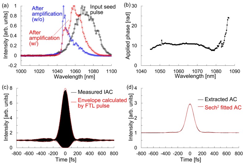
Figure 2(a) shows the spectra of the input seed pulse to the CPA system and the output pulses from the CPA system with and without the LPFs, which were measured using a spectrometer (Ocean Photonics, HR4000). We found that the gain narrowing was compensated by the LPFs. The optimized phase mask used to compensate the higher-order dispersion, which was applied to the LC-SLM in the pulse shaper, was created using a simulated annealing (SA) algorithm. In the SA method, the output of the CPA system was focused into a rhodamine B solution using a water-immersion objective lens (Olympus UPLSAPO60 × W) with a numerical aperture (NA) of 1.2, and the resultant 2PEF was detected by a photomultiplier tube (PMT: Hamamatsu Photonics, R4220) [24]. Figure 2(b) shows the optimized phase mask for maximizing the resultant 2PEF signal. After the optimization, we recorded the second-order interferometric autocorrelation (IAC) trace. Figure 2(c) shows the measured IAC trace and the upper and lower envelopes of the IAC trace obtained by the FTL pulse, which were calculated from the output pulse from the CPA system with the LPFs in Fig. 2(a). Since the IAC trace obtained from the experiment is in good agreement with that from the calculation, we concluded that the pulse at the focal plane was an FTL pulse. As shown in Fig. 2(d), we extracted the intensity autocorrelation (AC) trace from the IAC trace. The full width at half maximum (FWHM) of the intensity AC trace was 142 fs. Assuming a sech2 pulse shape, the pulse duration at the focal plane was estimated to be 92 fs.
Fig. 2.
(a) Spectra of the input seed pulse (black) to the CPA system and the output pulse from the CPA system with (red) and without (blue) the LPFs. (b) Optimized phase mask to compensate for the higher-order dispersion. (c) Measured IAC trace (black) and the upper and lower envelopes of the IAC trace calculated by the FTL pulse. (d) Extracted AC trace from the measured IAC trace in c and Sech2 fitted AC trace.
3. 3PEF-TF microscopy
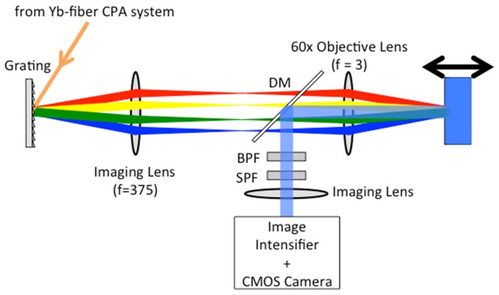
Figure 3 shows a schematic diagram of the TF microscope. The output from the Yb-fiber CPA system described in previous section was diffracted by an 830-grooves/mm grating. To avoid the tilt of the TF plane on the sample, the incident angle on the grating was adjusted to about 62° so that the diffraction angle of the pulse central frequency was zero. The beam diameter at 1/e2 on the grating was about 5.0 mm. The grating was imaged in the sample using the combination of an imaging lens with a focal length of 375 mm and a water-immersion objective lens (Olympus UPLSAPO60 × W) with a focal length of 3 mm and a numerical aperture (NA) of 1.2. The chromatic aberration of the objective lens was optimized for the spectral region from the visible to the near-infrared wavelength. The back aperture of the objective lens was overfilled in the spectrally-dispersed direction. The imaging lens was assembled from two achromatic doublets (Thorlabs, AC508-750-C) placed symmetrically around a small air gap, which is known as the Plössl eyepiece [28]. The generated fluorescence signal was collected using the same objective lens and separated from the excitation pulses using a dichroic mirror (DM; Thorlabs, DMLP900). To remove the residual excitation pulses, a short-pass filter (SPF, Semrock, FF01-890/SP-25) and a band-pass filter (BPF; Semrock, FF01-550/88-25 for 2PEF, FF02-435/40-25 for 3PEF, respectively) were used. The fluorescence images were transferred on an image intensifier (II: Hamamatsu Photonics, C9546) by an imaging lens, which was a visible achromatic doublet (Thorlabs, AC508-1000-A) with a focal length of 1 m. The chromatic aberration of the imaging lens was optimized for the visible region and the focal length of the imaging lens was long enough to neglect the aberration. The images amplified using the image intensifier were recorded by a CMOS camera (Hamamatsu Photonics, ORCA-Flash4.0). By scanning the sample in the axial (z) direction with a stepping motor-driven stage with a step size of 100 nm, the 3D image was obtained.
Fig. 3.
Schematic of the TF microscope. DM: dichroic mirror, SPF: short-pass filter, BPF: bandpass filter.
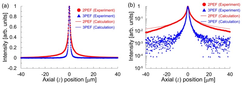
To estimate the excitation volume along the axial direction, we measured the signal distribution of one layer of 200-nm fluorescent beads (Molecular Probes, F8809 for 2PEF and F8805 for 3PEF). Figure 4 shows the measured signal distributions for the 2PEF-TF and 3PEF-TF microscopies, which were recorded using the PMT. The input powers for 2PEF-TF and 3PEF-TF microscopies were 5.5 mW and 55 mW, respectively. The exposure times were 100 ms. The FWHMs of the signal distributions for 2PEF-TF and 3PEF-TF were 2.1 µm and 1.6 µm, respectively. Thus, we found that the optical sectioning capability could be improved by a factor of 1.3 for 3PEF-TF. We evaluated the out-of-focus excitation for 2P-TF and 3P-TF from the full width at 1/100 maxima of the signal distributions, which were 69.2 µm and 11.8 µm, respectively. We were able to successfully suppress the out-of-focus excitation by a factor of 5.9.
Fig. 4.
Signal distribution of one layer of 200-nm fluorescent beads with (a) a linear scale and (b) a semi-logarithmic scale.
We also calculated the axial response of TF microscopy based on m-photon excitation. The axial response for 2PEF-TF microscopy is given by [29]
| (1) |
where z is the distance from the focal plane, and τ(z) is the pulse duration at z. The Rayleigh length zR is related to the optical sectioning capability provided by the TF effect, which depends on the NA of the objective lens, the spectrum of the excitation pulses, and the filling factor at the back focal plane of the objective lens. Since the 3PEF intensity is proportional to the cube of the excitation intensity I(z,t), the axial response for 3PEF-TF microscopy can be expressed as
| (2) |
where the excitation peak intensity Ipeak(z) is inversely proportional to the pulse duration τ(z). Figure 4 also shows the calculated axial responses for 2PEF-TF and 3PEF-TF microscopies with zR = 0.61 µm, which were determined using the FWHM of 2.1 µm for 2PEF-TF microscopy in the experiment. The axial responses obtained from the experiment are in good agreement with the calculated values. Therefore, we were able to confirm that the cubic dependence of the 3PEF intensity on the excitation intensity allowed for the further confinement of the excitation volume along the axial direction.
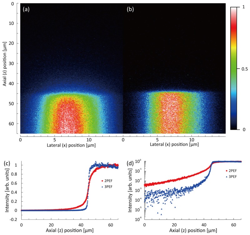
In order to confirm the suppression of the out-of-focus background fluorescence, we also measured the signal distribution along the axial direction around the interface between a cover slip and a fluorescent dye solution using 2PEF-TF and 3PEF-TF microscopies. The sample was rhodamine B for 2PEF-TF microscopy and coumarin 1 for 3PEF-TF microscopy. Solutions of rhodamine B and coumarin 1 in ethanol were diluted in glycerine to achieve a 50% glycerine-ethanol mixture. Figures 5(a) and 5(b) show measured x-z fluorescence images acquired with a 50-ms exposure time and input powers of 5.5 mW for 2PEF-TF microscopy and 110 mW for 3PEF-TF microscopy. Figure 5(c) shows the signal distribution along the axial (z) direction, which was obtained by taking the averages of signal intensities at 1024-neighboring pixels (32 × 32 pixels) around the center region in Figs. 5(a) and 5(b). Figure 5(d) shows a plot of the same data presented in Fig. 5(c) but on a semi-logarithmic scale. We can see that 3PEF-TF microscopy allows the background fluorescence to be suppressed significantly, and the edge in the fluorescence distribution is sharper than that for 2PEF-TF microscopy. We found that the signal intensity for 3PEF-TF microscopy slightly decreased at deeper positions. The signal reduction may be caused by the reabsorption of fluorescence and/or the spherical aberration caused by refractive-index mismatch between the immersion water and the dye solution. Compared with the 2PEF signal intensity, the 3PEF signal intensity is more sensitive to pulse duration change due to the spherical aberration as shown in Eqs. (1) and (2). Thus, we considered that the signal intensity at a deeper position for 3PEF-TF microscopy slightly decreased, while that for 2PEF-TF microscopy was maintained.
Fig. 5.
(a, b) x-z cross-sectional images of the interface between a cover slip and fluorescent dye solution measured by (a) 2PEF-TF and (b) 3PEF-TF microscopies. (c, d) Comparison of signal distribution along the axial (z) direction recorded using 2PEF-TF and 3PEF-TF microscopies plotted on (c) a linear scale and (d) a semi-logarithmic scale.
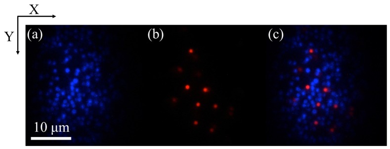
Next, we performed dual-color imaging of 1-μm orange (Molecular Probes, F8820) and blue (Molecular Probes, F8815) fluorescent beads using a combination of 2PEF-TF and 3PEF-TF microscopies. The emission wavelengths of the blue and orange beads were 440 nm and 560 nm, respectively, and the blue and orange beads were visualized by 3PEF-TF and 2PEF-TF microscopies, respectively. Figure 6 shows the dual-color images of the mixed beads sample, which were obtained by switching the band-pass filters. The images were acquired with an exposure time of 100 ms and input powers of 5.5 mW for 2PEF-TF microscopy and 83 mW for 3PEF-TF microscopy, respectively. As shown in Fig. 6, both beads could be easily recognized from the observed image, thus demonstrating successful dual-color imaging.
Fig. 6.
x-y cross-sectional images of 1-µm beads obtained using (a) 3PEF-TF, (b) 2PEF-TF microscopies, and (c) merged image of (a) and (b).
Finally, a combination of 2PEF-TF and 3PEF-TF microscopies was applied to dual-color imaging of a biological sample. Figure 7 shows images of the nucleus of fixed mouse brain tissue, which was stained with DAPI or SYTO83. The fluorescence images of DAPI-stained nuclei and SYTO83-stained nuclei were obtained by 3PEF-TF and 2PEF-TF microscopies, respectively. The exposure times were 30 ms, and the input powers were 83 mW for 2PEF-TF and 275 mW for 3PEF-TF microscopies, respectively. We obtained the dual-color images of the biological sample. DAPI and SYTO83 bind to RNA as well as DNA. However, fluorescence from DAPI-RNA is much weaker than from DAPI-DNA [30]. Thus, we cannot precisely compare the image obtained using 3PEF-TF microscopy with that obtained using 2PEF-TF microscopy. However, it was confirmed that the out-of-focus background fluorescence was lower for 3PEF-TF microscopy compared with that for 2PEF-TF microscopy.
Fig. 7.
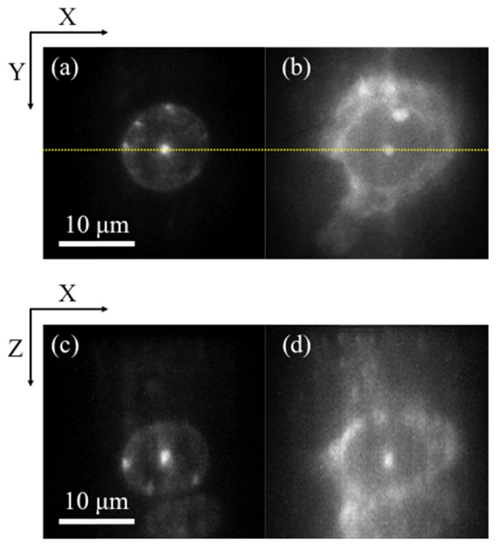
Dual-color images of fixed mouse brain tissue stained with DAPI and SYTO83. (a, b) x-y cross-sectional (a) 3PEF and (b) 2PEF images acquired at a depth of 30 µm. (c, d) x-z cross-sectional (c) 3PEF and (d) 2PEF images along the dotted lines indicated in (a, b).
4. Conclusions
We have demonstrated 3PEF-TF microscopy using a custom-built Yb-fiber CPA system at 1060 nm as the excitation light source. By compensating for gain narrowing with long-pass filters at 1050 nm and for higher-order dispersion with a 4-f pulse shaper, 92-fs FTL pulses with an energy of 9.0 μJ were generated at a repetition rate of 200 kHz. The optical sectioning capability of 3PEF-TF microscopy with an NA of 1.2 was improved from 2.1 μm to 1.6 μm compared with that of 2PEF-TF microscopy. The out-of-focus excitation, which was evaluated from the full width at 1/100 maximum intensity of the axial response, was also significantly suppressed by a factor of 5.9. We also successfully performed dual-color imaging of fluorescent beads with both 2PEF and 3PEF. By replacing the grating for TF with a digital micromirror device, 3PEF-TF microscopy can be easily combined with structured illumination microscopy [31]. In the future, we will apply this system to carry out dual-color super-resolution deep imaging of biological tissue. The 4-f pulse shaper with the LC-SLM could be used to compensate for the spectral phase distortion of the excitation pulse caused by the inhomogeneous refractive index distribution of biological tissue.
Acknowledgments
This work was supported by RIKEN Junior Research Associate Program.
Funding
Research Foundation for Opto-Science and Technology; JST/PRESTO (JPMJPR14F2).
References and links
- 1.Oron D., Tal E., Silberberg Y., “Scanningless depth-resolved microscopy,” Opt. Express 13(5), 1468–1476 (2005). 10.1364/OPEX.13.001468 [DOI] [PubMed] [Google Scholar]
- 2.Zhu G., van Howe J., Durst M., Zipfel W., Xu C., “Simultaneous spatial and temporal focusing of femtosecond pulses,” Opt. Express 13(6), 2153–2159 (2005). 10.1364/OPEX.13.002153 [DOI] [PubMed] [Google Scholar]
- 3.Therrien O. D., Aubé B., Pagès S., Koninck P. D., Côté D., “Wide-field multiphoton imaging of cellular dynamics in thick tissue by temporal focusing and patterned illumination,” Biomed. Opt. Express 2(3), 696–704 (2011). 10.1364/BOE.2.000696 [DOI] [PMC free article] [PubMed] [Google Scholar]
- 4.Cheng L.-C., Chang C.-Y., Lin C.-Y., Cho K.-C., Yen W.-C., Chang N.-S., Xu C., Dong C. Y., Chen S.-J., “Spatiotemporal focusing-based widefield multiphoton microscopy for fast optical sectioning,” Opt. Express 20(8), 8939–8948 (2012). 10.1364/OE.20.008939 [DOI] [PubMed] [Google Scholar]
- 5.Isobe K., Takeda T., Mochizuki K., Song Q., Suda A., Kannari F., Kawano H., Kumagai A., Miyawaki A., Midorikawa K., “Enhancement of lateral resolution and optical sectioning capability of two-photon fluorescence microscopy by combining temporal-focusing with structured illumination,” Biomed. Opt. Express 4(11), 2396–2410 (2013). 10.1364/BOE.4.002396 [DOI] [PMC free article] [PubMed] [Google Scholar]
- 6.Choi H., Yew E. Y. S., Hallacoglu B., Fantini S., Sheppard C. J. R., So P. T. C., “Improvement of axial resolution and contrast in temporally focused widefield two-photon microscopy with structured light illumination,” Biomed. Opt. Express 4(7), 995–1005 (2013). 10.1364/BOE.4.000995 [DOI] [PMC free article] [PubMed] [Google Scholar]
- 7.Tal E., Oron D., Silberberg Y., “Improved depth resolution in video-rate line-scanning multiphoton microscopy using temporal focusing,” Opt. Lett. 30(13), 1686–1688 (2005). 10.1364/OL.30.001686 [DOI] [PubMed] [Google Scholar]
- 8.Egner A., Hell S. W., “Time multiplexing and parallelization in multifocal multiphoton microscopy,” J. Opt. Soc. Am. A 17(7), 1192–1201 (2000). 10.1364/JOSAA.17.001192 [DOI] [PubMed] [Google Scholar]
- 9.Fittinghoff D., Wiseman P., Squier J., “Widefield multiphoton and temporally decorrelated multifocal multiphoton microscopy,” Opt. Express 7(8), 273–279 (2000). 10.1364/OE.7.000273 [DOI] [PubMed] [Google Scholar]
- 10.Vaziri A., Shank C. V., “Ultrafast widefield optical sectioning microscopy by multifocal temporal focusing,” Opt. Express 18(19), 19645–19655 (2010). 10.1364/OE.18.019645 [DOI] [PubMed] [Google Scholar]
- 11.Song Q., Nakamura A., Hirosawa K., Isobe K., Midorikawa K., Kannari F., “Two-dimensional spatiotemporal focusing of femtosecond pulses and its applications in microscopy,” Rev. Sci. Instrum. 86(8), 083701 (2015). 10.1063/1.4927532 [DOI] [PubMed] [Google Scholar]
- 12.Horton N. G., Wang K., Kobat D., Clark C. G., Wise F. W., Schaffer C. B., Xu C., “In vivo three-photon microscopy of subcortical structures within an intact mouse brain,” Nat. Photonics 7(3), 205–209 (2013). 10.1038/nphoton.2012.336 [DOI] [PMC free article] [PubMed] [Google Scholar]
- 13.Oron D., Silberberg Y., “Harmonic generation with temporally focused ultrashort pulses,” J. Opt. Soc. Am. B 22(12), 2660–2663 (2005). 10.1364/JOSAB.22.002660 [DOI] [Google Scholar]
- 14.Cheng L.-C., Horton N. G., Wang K., Chen S.-J., Xu C., “Measurements of multiphoton action cross sections for multiphoton microscopy,” Biomed. Opt. Express 5(10), 3427–3433 (2014). 10.1364/BOE.5.003427 [DOI] [PMC free article] [PubMed] [Google Scholar]
- 15.Donnert G., Eggeling C., Hell S. W., “Major signal increase in fluorescence microscopy through dark-state relaxation,” Nat. Methods 4(1), 81–86 (2007). 10.1038/nmeth986 [DOI] [PubMed] [Google Scholar]
- 16.Widengren J., Mets U., Rigler R., “Fluorescence correlation spectroscopy of triplet states in solution: a theoretical and experimental study,” J. Phys. Chem. 99(36), 13368–13379 (1995). 10.1021/j100036a009 [DOI] [Google Scholar]
- 17.Olivié G., Giguère D., Vidal F., Ozaki T., Kieffer J.-C., Nada O., Brunette I., “Wavelength dependence of femtosecond laser ablation threshold of corneal stroma,” Opt. Express 16(6), 4121–4129 (2008). 10.1364/OE.16.004121 [DOI] [PubMed] [Google Scholar]
- 18.Ritz J.-P., Roggan A., Isbert C., Müller G., Buhr H. J., Germer C.-T., “Optical properties of native and coagulated porcine liver tissue between 400 and 2400 nm,” Lasers Surg. Med. 29(3), 205–212 (2001). 10.1002/lsm.1134 [DOI] [PubMed] [Google Scholar]
- 19.Pask H. M., Carman R. J., Hanna D. C., Tropper A. C., Mackechnie C. J., Barber P. R., Dawes J. M., “Ytterbium-doped silica fiber lasers: versatile sources for the 1-1.2 μm region,” IEEE J. Sel. Top. Quantum Electron. 1(1), 2–13 (1995). 10.1109/2944.468377 [DOI] [Google Scholar]
- 20.Zhao Z., Kobayashi Y., “Ytterbium fiber-based, 270 fs, 100 W chirped pulse amplification laser system with 1 MHz repetition rate,” Appl. Phys. Express 9(1), 012701 (2016). 10.7567/APEX.9.012701 [DOI] [Google Scholar]
- 21.Kuznetsova L., Wise F. W., Kane S., Squier J., “Chirped-pulse amplification near the gain-narrowing limit of Yb-doped fiber using a reflection grism compressor,” Appl. Phys. B 88(4), 515–518 (2007). 10.1007/s00340-007-2699-2 [DOI] [Google Scholar]
- 22.Chiba Y., Takada H., Torizuka K., Misawa K., “65-fs Yb-doped fiber laser system with gain-narrowing compensation,” Opt. Express 23(5), 6809–6814 (2015). 10.1364/OE.23.006809 [DOI] [PubMed] [Google Scholar]
- 23.Zhao J., Li W., Wang C., Liu Y., Zeng H., “Pre-chirping management of a self-similar Yb-fiber amplifier towards 80 W average power with sub-40 fs pulse generation,” Opt. Express 22(26), 32214–32219 (2014). 10.1364/OE.22.032214 [DOI] [PubMed] [Google Scholar]
- 24.Isobe K., Suda A., Tanaka M., Hashimoto H., Kannari F., Kawano H., Mizuno H., Miyawaki A., Midorikawa K., “Nonlinear optical microscopy and spectroscopy employing octave spanning pulses,” IEEE J. Sel. Top. Quantum Electron. 16(4), 767–780 (2010). 10.1109/JSTQE.2009.2037439 [DOI] [Google Scholar]
- 25.Zhou X., Yoshitomi D., Kobayashi Y., Torizuka K., “Generation of 28-fs pulses from a mode-locked ytterbium fiber oscillator,” Opt. Express 16(10), 7055–7059 (2008). 10.1364/OE.16.007055 [DOI] [PubMed] [Google Scholar]
- 26.Tanabe T., Kannari F., Korte F., Koch J., Chichkov B., “Influence of spatiotemporal coupling induced by an ultrashort laser pulse shaper on a focused beam profile,” Appl. Opt. 44(6), 1092–1098 (2005). 10.1364/AO.44.001092 [DOI] [PubMed] [Google Scholar]
- 27.Desurvire E., “Analysis of gain difference between forward- and backward-pumped erbium-doped fiber amplifiers in the saturation regime,” IEEE Photonics Technol. Lett. 4(7), 711–714 (1992). 10.1109/68.145247 [DOI] [Google Scholar]
- 28.A. Nagler, “Plossl type eyepiece for use in astronomical instruments,” US Patent 4,482,217 (1984).
- 29.Durst M. E., Zhu G., Xu C., “Simultaneous spatial and temporal focusing for axial scanning,” Opt. Express 14(25), 12243–12254 (2006). 10.1364/OE.14.012243 [DOI] [PubMed] [Google Scholar]
- 30.Kapuściński J., Yanagi K., “Selective staining by 4’, 6-diamidine-2-phenylindole of nanogram quantities of DNA in the presence of RNA on gels,” Nucleic Acids Res. 6(11), 3535–3542 (1979). 10.1093/nar/6.11.3535 [DOI] [PMC free article] [PubMed] [Google Scholar]
- 31.Isobe K., Toda K., Song Q., Kannari F., Kawano H., Miyawaki A., Midorikawa K., “Temporal focusing microscopy combined with three-dimensional structured illumination,” Jpn. J. Appl. Phys. 56(5), 052501 (2017). 10.7567/JJAP.56.052501 [DOI] [Google Scholar]


