Abstract
Fiber-optic endomicroscopes open new avenues for the application of non-linear optics to novel in vivo applications. To achieve focus scanning in vivo, shape memory alloy (SMA) wires have been used to move optical elements in miniature endomicroscopes. However, this method has various limitations, making it difficult to achieve accurate and reliable depth scanning. Here we present a feedback-controlled SMA depth scanner. With a Hall effect sensor, contraction of the SMA wire can be tracked in real time, rendering accurate and robust control of motion. The SMA depth scanner can achieve up to 490 µm travel and with open-loop operation, it can move more than 350 µm within one second. With the feedback loop engaged, submicron positioning accuracy was achieved along with superior positioning stability. The high-precision positioning capability of the SMA depth scanner was verified by depth-resolved nonlinear endomicroscopic imaging of mouse brain samples.
OCIS codes: (110.0110) Imaging systems, (170.2150) Endoscopic imaging, (180.0180) Microscopy, (190.0190) Nonlinear optics
1. Introduction
Fiber-optic nonlinear endomicroscopy allows several potential in vivo applications of nonlinear microscopy technologies, such as assessing the cervical consistency during pregnancy [1] and mapping neuronal activity in the brains of freely moving animals [2]. In an endomicroscopic imaging setting, two-dimensional lateral beam scanning has been accomplished by various methods, including the use of a piezo-based scanner to perform spiral scan [3], Lissajous scan [4] or raster scan [5], and the use of a miniature MEMS mirror [6, 7]. To fully utilize the three-dimensional imaging capability of nonlinear microscopy, a depth or focus scan mechanism is needed. Conventionally, depth scanning has been achieved by mounting the endomicroscope on a translational stage, or using a pull-back mechanism at the proximal end [8]. However, these methods have distinct limitations, as they increase the size of the instrument or have low accuracy, making them unsuitable for in vivo applications. In addition, the size and weight limit posed by mounting devices on the heads of small mammals such as mice for brain imaging, requires a mechanism that allows for accurate and reliable depth scanning, while maintaining a small form factor.
One way to achieve depth scanning is to vary the focal length of a lens directly with tunable lens technology [9, 10]. However, for nonlinear endomicroscopy, a high numerical aperture (NA) lens with superior achromaticity is required [1, 11, 12], and this is particularly challenging for a tunable lens [13]. Another way to achieve depth scanning is to directly translate the endomicroscope optics, using technologies such as shape memory alloys (SMA) [14], voice coil motors (VCM) [15], or pneumatic actuation [16]. Among the various technologies, SMA wires have shown promise in extending 2D endoscopic imaging to 3D; by Joule heating, the SMA wire contracts and moves the endomicroscope optics to change the beam focus [14]. However, this method suffers from hysteresis, and is susceptible to changes in ambient temperature, making it difficult to achieve accurate and reliable depth scanning.
In this paper, we describe a feedback-controlled SMA depth scanner which addresses these challenges. The core of the feedback loop was a Hall effect sensor. By measuring the magnetic flux density from a tiny magnet attached to the SMA wire, the contraction distance of the SMA wire could be accurately tracked in real time. The measured displacement was then fed to the PID algorithm running on a microprocessor, which computed the error between the command position and the current position of the depth scanner. The electrical current running through the SMA wire was then adjusted accordingly. This feedback-controlled SMA depth scanner had a tube shape with an outer diameter of 6.5 millimeters, and was designed to house a 2.1 mm endomicroscope inside. The SMA depth scanner can travel up to 490 µm, and with an open-loop operation, it can move more than 350 µm within a second. With the feedback loop engaged, submicron positioning accuracy was achieved along with superior long term positioning stability. The high-precision positioning capability of the SMA depth scanner was further verified by depth-resolved nonlinear endomicroscopic imaging of biological samples.
2. Methods
2.1 SMA and its hysteresis
SMA is a special kind of alloy that has memory of its original shape. When heated above the transition temperature, SMA will restore to its original shape if deformed [17]. In this work, we employed the commercially available FLEXINOL® wire, which was made from nickel-titanium shape memory alloy. SMA wire is compact, lightweight, and easy to use. By passing electrical current through the wire, Joule heating can cause the SMA wire to contract 3-5% of its total length, and to generate sufficient pull force. Table 1 shows the key parameters of the SMA wire used in this work.
Table 1. Key Parameters of the SMA Wire.
| Parameters | Value |
|---|---|
| Diameter | 125 μm |
| Activation temperature | 90 °C |
| Resistance | 75 Ω/m |
| Recommended current | 320 mA |
| Pull force | 223 g |
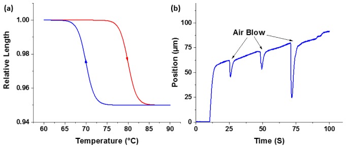
It is well known that shape memory alloy suffers from hysteresis; when heated or cooled, the SMA wire does not have the same response upon temperature change [18]. As shown in Fig. 1(a), when an SMA wire is heated, it follows the upper red contraction curve, but when it is cooling down, the wire follows the bottom blue relaxation curve. In addition to hysteresis, the SMA wire is susceptible to changes in ambient temperature. As shown in Fig. 1(b), a constant current was applied to an SMA wire, and it contracted in response to the rise in temperature. The contraction could be easily perturbed by slight cooling (Air Blow), as depicted as ‘dips’ in the curve. The hysteresis response of the SMA wire, as well as its susceptibility to temperature perturbations posed major challenges in precise and robust control of its contraction and relaxation.
Fig. 1.
(a) Hysteresis response of the SMA wire. (b) Susceptibility of the SMA wire to ambient temperature change.
2.2 Feedback loop
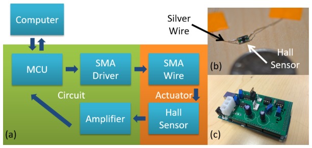
To address these challenges, a feedback loop was introduced to actively stabilize the contraction or relaxation of the SMA wire. The feedback loop consisted of (1) a position sensor, (2) a microcontroller unit (MCU), and (3) the corresponding driving and amplification circuitry. The position sensor measured the SMA wire displacement. The measured displacement was then amplified and fed into the MCU. The MCU compared the measured position with the desired position set by the user (denoted as command position) and adjusted the electrical current in the SMA wire accordingly to deform the SMA further and bring the scanner to the command position. The block diagram of the feedback loop is shown in Fig. 2(a).
Fig. 2.
(a) Block diagram of the feedback loop. (b) Photo of a Hall effect sensor. (c) Photo of the MCU and circuitry.
The position sensor consists of a Hall effect sensor and a neodymium magnet. The Hall effect sensor was fixed in position with the magnet attached to the moving part of the SMA depth scanner. The displacement of SMA wire leads to a change in magnetic flux density around the Hall effect sensor. This change in magnetic field was further translated into voltages per the Hall effect. The small Hall voltage output from the sensor was then amplified and passed on to the digitizer of the MCU. In this way, contraction of the SMA wire could be accurately measured by the MCU. A photo of the Hall effect sensor is shown in Fig. 2(b).
The driving and amplification circuitry allows the MCU to track the displacement and control the SMA wire in real time. Figure 2(c) shows a photo of the MCU, and its driving and amplification circuitry. The driving circuitry was a current source that can be turned on and off at a high frequency via the pulse width modulation (PWM) functionality of the MCU. The PWM cycle period was set to 64 µs, orders of magnitude below the heating response time of the SMA wire, so that the wire was heated as if a constant current was applied. In addition, by changing the duty cycle of the on-off current, the heating power in the SMA wire could be accurately controlled. The amplification circuitry increased the small Hall sensor output. To ensure maximum sensitivity, this circuitry enhanced the Hall sensor output by subtracting the output voltage from a preset zero which was then amplified by 12 times to match the 5V input range of the MCU digitizer. The preset zero-point voltage was to ensure a zero output from the amplifier when the SMA wire was relaxed. The MCU digitizer was running at a sampling rate of 100 Hz, and every 100 milliseconds, an average of 10 latest samples was used as the input to the control algorithm.
The final link of the feedback loop was the PID algorithm running on the MCU. The MCU (Arduino Mega 2560) received the user-defined desired voltage from a computer and stored it in its memory. Then it compared the desired voltage with the current averaged voltage readout from its digitizer, computed the error between the two, and adjusted the heating power in the SMA wire based on PID algorithm [19].
2.3 Construction of the SMA depth scanner
To adapt the scanner for use with an endomicroscope, we modified the components to achieve a compact design with reasonable positioning precision. Figure 3(a) is the functional illustration of the depth scanner: an SMA wire and a rubber band are installed in an antiparallel fashion, pulling the endomicroscope to opposite directions. They both have one end attached to the endomicroscope, and the other end fixed in space. When a current is applied, the SMA wire heats up and contracts, pulling the endomicroscope to the left in Fig. 3 (towards the imaged sample). Conversely, when the current is turned off, the SMA wire cools and relaxes; the rubber band then pulls the endomicroscope back to the right (away from the imaged sample), as indicated by the two red arrows. The magnet is attached to the moving endomicroscope, and the Hall effect sensor is fixed. The Hall effect sensor and the magnet are kept as close as possible to each other, ensuring maximum sensitivity.
Fig. 3.
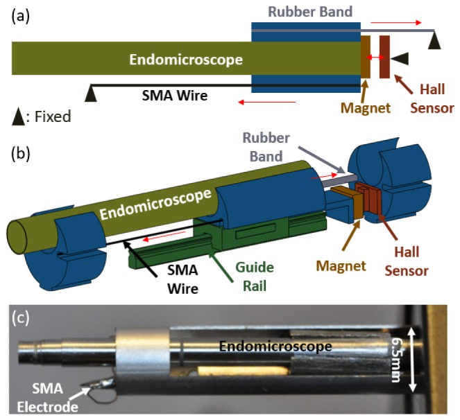
(a) Functional illustration of the depth scanner. (b) Perspective view of the depth scanner without the outer housing. (c) Picture of the SMA depth scanner with the encased endomicroscope.
Since only a single SMA wire was used in the design, the pull force was not balanced and the endomicroscope had the tendency to twist itself during translation. To address this problem and minimize friction, a miniature guide rail with ball bearing was introduced, as shown in Fig. 3(b). The endomicroscope was mounted on the moving carriage of the guide rail. The SMA wire and the rubber band were also attached to the moving carriage, pulling the endomicroscope to opposite directions. The whole assembly was housed inside a gauge-3 hypodermic tube, with an outer diameter of 6.5 mm (Fig. 3(c)). In this proof-of-concept design, the outer diameter of the depth scanner was primarily determined by the guide rail, which was purchased from available materials rather than constructed in house. We foresee that with proper design and customization, the outer diameter of the depth scanner can be potentially reduced to half of the current size.
2.4 Calibration of the Hall effect sensor
With the feedback loop, movement of the SMA wire could be stabilized with a user-defined digitized voltage. Calibration was performed to establish the relationship between the digitized voltage and the actual displacement. We first calculated the exact size of individual pixels of a given camera. Then we captured on the same camera the displacement of the SMA scanner once it was steady in position at each command voltage. The photographed SMA travel was then translated into actual distance in microns. In this way, the relationship between the digitized voltage and the actual displacement was established, and the data points were fit to a 2nd order polynomial (Fig. 4). Submicron positioning accuracy could be achieved with the feedback loop engaged. As shown in Fig. 4, the 400 µm travel range corresponds to 900 digitized voltage readout levels of the Hall effect sensor by the analog-to-digital converter (ADC) on the MCU of a 10-bit resolution, which gives ~0.44 µm step size on average. A better step size resolution can be achieved by using an MCU featuring a finer resolution ADC.
Fig. 4.
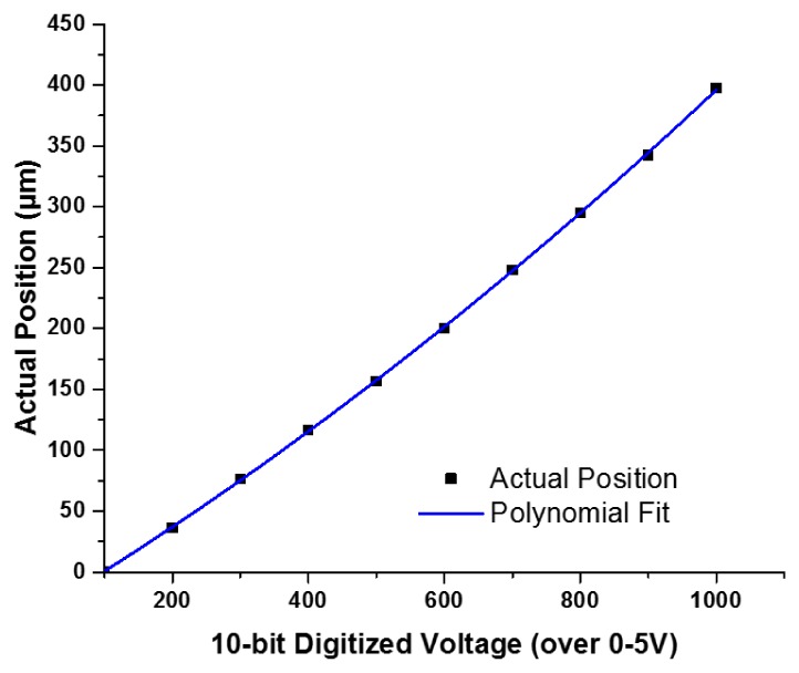
Hall effect sensor calibration curve
2.5 3D Endomicroscopic imaging system
Figure 5 shows the schematic of the 3D endomicroscopic imaging system used in this study. The details of the nonlinear endomicroscope were described elsewhere [3]. A Ti:Sapphire laser pre-chirped by a grating pair (GP) was coupled into the endomicroscope through the core of a double-clad fiber (DCF) for excitation. The nonlinear optical signals from the samples were collected both by the core and inner clad of the DCF, and directed to a photomultiplier tube (PMT). The fiber-optic resonant scanner (FRS) created a spiral scanning pattern of ~200 µm in diameter. Depth-resolved images were taken as the SMA depth scanner accurately moved the endomicroscope up and down.
Fig. 5.
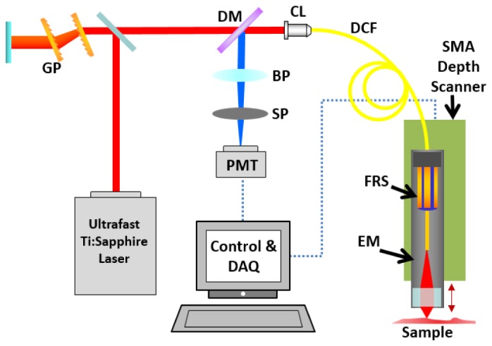
Schematic of the 3D endomicroscopic imaging system. GP: Grating Pair; DM: Dichroic Mirror; BP: Band-pass Filter; SP: Short-pass Filter; PMT: Photomultiplier Tube; CL: Coupling Lens; DCF: Double-clad Fiber; FRS: Fiber-optic Resonant Scanner; EM: Endomicroscope.
3. Results and discussions
3.1 Positioning performance
To test the range of the depth scanner, the SMA wire was driven to its limit with the maximum heating current. The maximum heating current was set to 320 mA to prevent the SMA wire from burning, and a 490 µm scanning range was achieved. This corresponded to 3% of the total lengths of the 1.6 cm long SMA wire used in our system, which agreed well with the 3% to 5% contraction range specified by the manufacturer. Even with maximum current applied to the SMA wire and the SMA wire reaching the actuation temperature of 90 degree Celsius, no obvious rise of temperature could be detected on the outer surface of the depth scanner housing. The reason was that there was little voltage drop across the SMA wire, yielding a heating power of merely 122 mW.
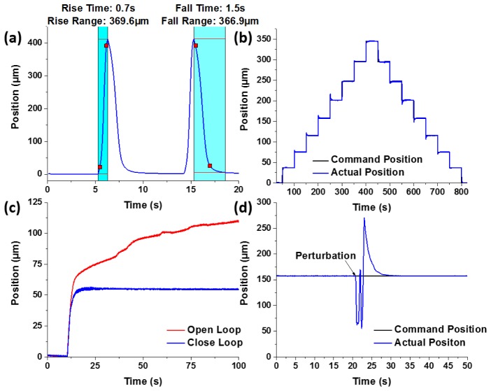
The actuation speed was tested under open-loop conditions where the SMA wire was given an instant jump (step drive function) of drive current to its maximum value (320 mA), and the movement was tracked in real time with the calibrated Hall sensor. As shown in Fig. 6(a), it took the SMA depth scanner 0.7 seconds to move about 369.6 µm in contraction, and 1.5 seconds to move 366.9 µm in relaxation. This open-loop movement was rapid and continuous, and the position of the scanner could be tracked in real time by the Hall effect sensor. This open-loop operation mode can be used in depth-priority scanning for imaging modalities with sufficiently high frame rate.
Fig. 6.
(a) Open-loop rapid operation of the SMA depth scanner. (b) Close-loop operation of the SMA depth scanner. (c) Stability of the SMA scanner in open/close-loop operations. (d) Perturbation test for close-loop operation of the SMA scanner.
With the feedback loop engaged, the arbitrary positioning capability of the SMA depth scanner was tested by setting different command positions in the MCU, while tracking the change of the position over time. Figure 6(b) shows the change of position over time when given a series of different command positions at different times, and the actual positions closely followed the command positions. The positioning accuracy was defined as the root-mean-square (RMS) of the deviation between the actual position and the command position at a given steady state, and it was calculated to be 0.45 µm.
The positioning stability is crucial for imaging modalities with a relatively low frame rate, such as nonlinear endomicroscopy. Sharp images can only be acquired when the endomicroscope position is stabilized. Figure 6(c) shows the stability of the depth scanner in close-loop operation as opposed to the open-loop constant current operation. In the close-loop case, the feedback loop locked the position of the depth scanner for a long time with negligible fluctuations. However, in the open-loop case, the depth scanner drifted dramatically and constantly, and it was unable to stabilize itself even after 100 seconds. Note that after a command was given to the feedback-controlled depth scanner, it took about 10 seconds for the SMA wire to stabilize at a target position, this was due to the conservative PID parameters chosen for better stability and accuracy. And this conservative PID tuning lead to an underdamped motion with a slow oscillation of about half a micron in amplitude. Since the response of the SMA wire is highly nonlinear, it is rather challenging to find a set of PID parameters that allowed for high speed actuation and superior accuracy at the same time. And this problem can be potentially addressed with more advanced nonlinear control algorithms [20].
Another unique feature of the feedback-controlled SMA depth scanner is that it can easily recover from perturbations. As demonstrated in Fig. 6(d), when the SMA wire was in a steady state for a given command position, a strong blow of cold air from a compressed-gas duster was applied. This caused a sudden drop in the SMA temperature, and hence the elongation of its length. Shortly afterwards, the SMA depth scanner managed to recover itself to the previous steady state by the feedback loop.
3.2 Depth-resolved nonlinear endomicroscopy imaging
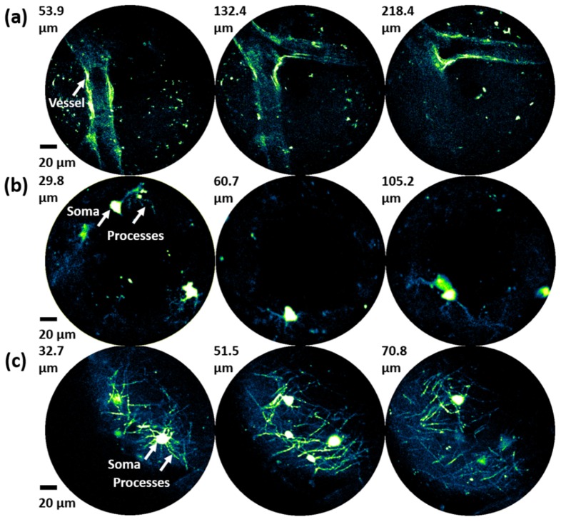
The precision positioning capability of the SMA depth scanner was further verified by depth-resolved two-photon imaging of mouse brain samples with the 3D endomicroscopy imaging system shown in Fig. 5. The endomicroscope was first manually focused onto the surface of the sample to locate a region of interest, and then the SMA depth scanner was activated to move the endomicroscope up and down to different focal depths. Imaging was performed using brain samples from three different lines of transgenic mice. The first was a mouse brain that underwent CUBIC optical clearing [21]. Figure 7(a) shows the two-photon fluorescence images of a region in the brain in which a large branching blood vessel with autofluorescence is visible. The second brain sample was from a mouse that was bred by crossing Pdgfra-creER mice (JAX 018280) [22] with RCE:loxP mice (MMRRC 32037-JAX), where EGFP is expressed in oligodendrocyte precursor cells (OPCs). Our endomicroscopic imaging setup was able to resolve individual somata as well as the fine processes of OPCs at different depths (Fig. 7(b)). The third brain sample was from an MOBP-EGFP mouse (MGI 4847238), in which EGFP is expressed in mature oligodendrocytes. As shown in Fig. 7(c), the somata of the oligodendrocytes and the individual myelin sheaths (internodes) formed by their processes are clearly resolved at different depths.
Fig. 7.
(a) Depth-resolved blood vessel in the CUBIC mouse brain. (b) Depth-resolved somata and processes of OPCs in the Pdgfra-creER; RCE:loxP brain. (c) Depth-resolved somata and processes (myelin sheath internodes of oligodendrocytes) in the MOBP-EGFP brain. OPC: oligodendrocyte precursor cell.
4. Conclusion
In conclusion, we developed a feed-back controlled SMA depth scanner. The depth scanner had a small form factor with an outer diameter of 6.5 mm. It could travel up to 490 µm in distance. With open-loop operation, it could move more than 350 µm within one second. With the feedback loop engaged, submicron positioning accuracy was achieved along with superior positioning stability. It is expected that the size of the depth scanner can be further reduced by special customization, and the close-loop actuation speed can be improved by using more advanced nonlinear control algorithms. This design greatly extends the capabilities of miniature endomicroscopes by allowing stable, depth resolved imaging in biological tissues.
Funding
National Institutes of Health (R01CA153023); National Science Foundation (CBET-1430040); Johns Hopkins Synergy/Discovery Fund.
Reference and links
- 1.Zhang Y., Akins M. L., Murari K., Xi J., Li M.-J., Luby-Phelps K., Mahendroo M., Li X., “A compact fiber-optic SHG scanning endomicroscope and its application to visualize cervical remodeling during pregnancy,” Proc. Natl. Acad. Sci. U.S.A. 109(32), 12878–12883 (2012). 10.1073/pnas.1121495109 [DOI] [PMC free article] [PubMed] [Google Scholar]
- 2.Helmchen F., Fee M. S., Tank D. W., Denk W., “A miniature head-mounted two-photon microscope. high-resolution brain imaging in freely moving animals,” Neuron 31(6), 903–912 (2001). 10.1016/S0896-6273(01)00421-4 [DOI] [PubMed] [Google Scholar]
- 3.Myaing M. T., MacDonald D. J., Li X., “Fiber-optic scanning two-photon fluorescence endoscope,” Opt. Lett. 31(8), 1076–1078 (2006). 10.1364/OL.31.001076 [DOI] [PubMed] [Google Scholar]
- 4.Liang W., Murari K., Zhang Y., Chen Y., Li M.-J., Li X., “Increased illumination uniformity and reduced photodamage offered by the Lissajous scanning in fiber-optic two-photon endomicroscopy,” J. Biomed. Opt. 17(2), 021108 (2012). 10.1117/1.JBO.17.2.021108 [DOI] [PMC free article] [PubMed] [Google Scholar]
- 5.Rivera D. R., Brown C. M., Ouzounov D. G., Pavlova I., Kobat D., Webb W. W., Xu C., “Compact and flexible raster scanning multiphoton endoscope capable of imaging unstained tissue,” Proc. Natl. Acad. Sci. U.S.A. 108(43), 17598–17603 (2011). 10.1073/pnas.1114746108 [DOI] [PMC free article] [PubMed] [Google Scholar]
- 6.Fu L., Jain A., Xie H., Cranfield C., Gu M., “Nonlinear optical endoscopy based on a double-clad photonic crystal fiber and a MEMS mirror,” Opt. Express 14(3), 1027–1032 (2006). 10.1364/OE.14.001027 [DOI] [PubMed] [Google Scholar]
- 7.Tang S., Jung W., McCormick D., Xie T., Su J., Ahn Y.-C., Tromberg B. J., Chen Z., “Design and implementation of fiber-based multiphoton endoscopy with microelectromechanical systems scanning,” J. Biomed. Opt. 14(3), 034005 (2009). 10.1117/1.3127203 [DOI] [PMC free article] [PubMed] [Google Scholar]
- 8.Mavadia J., Xi J., Chen Y., Li X., “An all-fiber-optic endoscopy platform for simultaneous OCT and fluorescence imaging,” Biomed. Opt. Express 3(11), 2851–2859 (2012). 10.1364/BOE.3.002851 [DOI] [PMC free article] [PubMed] [Google Scholar]
- 9.Campbell K., Fainman Y., Groisman A., “Pneumatically actuated adaptive lenses with millisecond response time,” Appl. Phys. Lett. 91(17), 171111 (2007). 10.1063/1.2801983 [DOI] [Google Scholar]
- 10.Zeng X., Jiang H., “Tunable liquid microlens actuated by infrared light-responsive hydrogel,” Appl. Phys. Lett. 93(15), 151101 (2008). 10.1063/1.2996271 [DOI] [Google Scholar]
- 11.Wu Y., Xi J., Cobb M. J., Li X., “Scanning fiber-optic nonlinear endomicroscopy with miniature aspherical compound lens and multimode fiber collector,” Opt. Lett. 34(7), 953–955 (2009). 10.1364/OL.34.000953 [DOI] [PMC free article] [PubMed] [Google Scholar]
- 12.Wu Y., Li X., “Combined influences of chromatic aberration and scattering in depth-resolved two-photon fluorescence endospectroscopy,” Biomed. Opt. Express 1(4), 1234–1243 (2010). 10.1364/BOE.1.001234 [DOI] [PMC free article] [PubMed] [Google Scholar]
- 13.Grewe B. F., Voigt F. F., van ’t Hoff M., Helmchen F., “Fast two-layer two-photon imaging of neuronal cell populations using an electrically tunable lens,” Biomed. Opt. Express 2(7), 2035–2046 (2011). 10.1364/BOE.2.002035 [DOI] [PMC free article] [PubMed] [Google Scholar]
- 14.Wu Y., Zhang Y., Xi J., Li M.-J., Li X., “Fiber-optic nonlinear endomicroscopy with focus scanning by using shape memory alloy actuation,” J. Biomed. Opt. 15(6), 060506 (2010). 10.1117/1.3523234 [DOI] [PMC free article] [PubMed] [Google Scholar]
- 15.Liu C. S., Lin P. D., Lin P. H., Ke S. S., Chang Y. H., Horng J. B., “Design and characterization of miniature auto-focusing voice coil motor actuator for cell phone camera applications,” IEEE Trans. Magn. 45(1), 155–159 (2009). 10.1109/TMAG.2008.2006564 [DOI] [Google Scholar]
- 16.Lim Y. M., Lee J., Park J., Kim B., Park J. O., Kim S. H., Hong Y. S., “A self-propelling endoscopic system,” IEEE International Conference on Intelligent Robots and Systems 2, 1117–1122 (2001). [Google Scholar]
- 17.Otsuka K., Ren X., “Recent developments in the research of shape memory alloys,” Intermetallics 7(5), 511–528 (1999). 10.1016/S0966-9795(98)00070-3 [DOI] [Google Scholar]
- 18.Dutta S. M., Ghorbel F. H., “Differential hysteresis modeling of a shape memory alloy wire actuator,” IEEE/ASME Trans. Mechatron. 10(2), 189–197 (2005). 10.1109/TMECH.2005.844709 [DOI] [Google Scholar]
- 19.Åström K. J., Hägglund T., PID Controllers: Theory, Design, and Tuning (Instrument Society of America, 1995). [Google Scholar]
- 20.Su C.-Y., Stepanenko Y., Svoboda J., Leung T.-P., “Robust adaptive control of a class of nonlinear systems with unknown backlash-like hysteresis,” IEEE Trans. Automat. Contr. 45(12), 2427–2432 (2000). 10.1109/9.895588 [DOI] [Google Scholar]
- 21.Susaki E. A., Tainaka K., Perrin D., Yukinaga H., Kuno A., Ueda H. R., “Advanced CUBIC protocols for whole-brain and whole-body clearing and imaging,” Nat. Protoc. 10(11), 1709–1727 (2015). 10.1038/nprot.2015.085 [DOI] [PubMed] [Google Scholar]
- 22.Kang S. H., Fukaya M., Yang J. K., Rothstein J. D., Bergles D. E., “NG2+ CNS glial progenitors remain committed to the oligodendrocyte lineage in postnatal life and following neurodegeneration,” Neuron 68(4), 668–681 (2010). 10.1016/j.neuron.2010.09.009 [DOI] [PMC free article] [PubMed] [Google Scholar]


