Abstract
In this paper, we demonstrate the ability of structured illumination microscopy to enhance the ability of fluorescence lifetime imaging to resolve fluorescence lifetimes in relatively thick samples that possess distinct but spectrally overlapping fluorescent layers. Structured illumination fluorescent lifetime imaging microscopy (SI-FLIM) is shown to be able to accurately reconstruct lifetime values in homogenous fluorophore samples (POPOP, NADH, and FAD) as well as accurately measure fluorescent lifetime in two layer models that are layered with NADH/FAD over POPOP, where NADH/FAD and POPOP have spectral overlap. Finally, the ability of SI-FLIM was demonstrated in a hamster cheek pouch ex vivo to show that more accurate lifetimes could be measured for each layer of interest in the oral mucosa (epithelium and submucosa).
OCIS codes: (110.0180) Microscopy, (110.6880) Three-dimensional image acquisition, (170.3880) Medical and biological imaging
1. Introduction
Fluorescence lifetime imaging microscopy (FLIM) is a widely studied imaging modality that is most commonly used for its ability to distinguish multiple fluorophores of similar spectral characteristics, thus allowing for the chemical analysis of microscopy samples via both their fluorescence spectral and temporal properties. It is particularly attractive because it allows for high resolution spatial analysis of chemical distributions with little to no dependence on the intensity or concentration of the fluorophores under scrutiny [1]. Several techniques exist for measuring lifetimes such as time correlated single photon counting (TCSPC), direct decay via high bandwidth photomultiplier tube (PMT), and wide-field imaging via intensified CCD (ICCD) [2]. When considering biomedical applications, it is important to choose a FLIM modality that can function effectively in vivo. The wide-field imaging approach is well suited for this task because it allows for the rapid measurement of fluorescent lifetimes at greater than 2 frames per second, while maintaining a relatively large field of view [3]. In contrast to other FLIM methods that are typically based on laser scanning techniques, wide-field imaging decouples field of view from imaging speed, allowing for faster acquisition that is less susceptible to motion artifacts, a necessity for in vivo FLIM.
However, FLIM suffers adversely from the effects of out of focus light where background contributions to the intensity can lower the measured fluorescence lifetime contrast between layers and lead to incorrectly calculated lifetime values [4]. Multiple exponential fitting methods exist to alleviate the problems that occur with spatially overlapping intensities, but these generally lengthen acquisition by requiring more than two gates and complicate the lifetime calculation processes [5]. A potentially simpler method is to separately image the intensities in the focal plane while minimizing contributions from the background with the use of optical sectioning techniques. Several optical sectioning techniques have been implemented in conjunction with FLIM such as two-photon, confocal, and structured illumination microscopy [2, 6]. We utilize structured illumination instead of other sectioning alternatives as it provides a means to optically section with a wide-field imaging modality, an important consideration for in vivo application. Structured illumination microscopy (SIM) provides sectioning by spatially modulating the in-focus content of the focal plane by using a modulated illumination source. Using single side band demodulation and reconstruction theory, the sample can be illuminated with a sinusoidally varying pattern at multiple phase positions and be recombined to retain in-focus content and reject out-of-focus content [7]. Although SIM has been shown to be able to provide accurate lifetime measurements when used in conjunction with FLIM, accurately resolving multiple layers with different lifetimes in thick samples such as tissue has yet to be demonstrated. A major aim of the research presented herein is to be able to differentiate the fluorescence signal originating from the oral epithelium, where the bulk of the fluorescence signal is known to be associated with FAD and NADH, from that of the underlying collagen-containing submucosa. We aim to demonstrate that this technique can be used for imaging fluorescence lifetime in relatively thick tissue samples such as oral epithelium.
2. Materials and methods
2.1 SI-FLIM system design
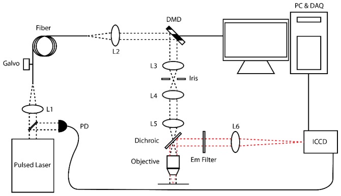
To measure fluorescence lifetimes with sectioning capability, we constructed a standard wide-field epi-fluorescence microscope. Figure 1 shows the layout of the SI-FLIM system. An 800 ps pulse width, 355 nm wavelength, laser (AOT-YVO-100QSP/MOPA) operated at 6.25 kHz is coupled into a 400 μm core fiber via a 100 mm focal length lens (LA4380, Thorlabs). The laser delivered an average power of 1 mW to the sample with a peak power of 176 mW. The 400 μm core fiber was chosen because it allowed a pseudo flat-top super Gaussian illumination profile. The fiber is attached to a galvanometer scanner motor and vibrated to reduce the effects of laser speckle and mode patterns. A 50 mm lens (LA4765, Thorlabs) is used to collimate the output of the fiber to fill the full aperture of a DMD, digital micro mirror device, (DLi D4100, DLi) window with 1024x768 resolution and 13.68 μm pixel pitch. Using 24 pixels per line, this resulted in modulation frequency of 30.45 lines per mm at the sample. Light from the DMD is then spatially filtered using two 50 mm focal length lenses (65-976, Edmund Optics) and an iris to pass only the 1st diffraction order; this helps maintain good contrast of the DMD pattern. A 100 mm field lens (65-979, Edmund Optics) then relays the illumination intensity to the rear focal plane of the 20 × objective (N20X-PF, Thorlabs). The objective is placed so that the DMD is in a conjugate image plane relative to the objective focal plane, while the image of the light source is in a Fourier plane.
Fig. 1.
SI-FLIM system schematic. L1: fiber coupling lens; L2: collection/collimation lens; L3/L4: 1:1 spatial filter lens pair; L5: field lens; L6: tube lens; ICCD: intensified CCD camera; PD: photodiode. Black dashed lines represent the field; red dotted lines represent the image.
A dichroic beam splitter (FF365-Di01-25x36, Semrock) is used in conjunction with three different emission filters to separate the image intensities into three separate spectral bands: 390 nm +/− 20 nm (86-348, Edmund Optics), 450 +/− 20 nm (FB450-40, Thorlabs), and 550 +/− 16 nm (BrightLine550-32, Semrock). The fluorophores associated with these emission bands are collagen/POPOP, NADH, and FAD, respectively. The emission filters are mounted in a slip mount (SMQ1P, Thorlabs) so that they can be quickly swapped with one another into the beam path. The tube lens (ITL200, Thorlabs) then forms an image on the ICCD camera (4Picos, Stanford Computer Optics). The ICCD camera can be gated and delayed with at temporal resolution of 200 ps. The gates chosen were specific to the expected lifetimes being measured with the gates for POPOP, NADH, and FAD being 1.3 ns, 0.5 ns, and 2.5 ns, respectively. The camera is set to trigger off of a high speed photodiode (SV2, Thorlabs) that reads light from a ~95/5 beam splitter (BSF10-UV, Thorlabs) pick off placed just after the laser output and before the coupling lens. This method ensures that the camera is always triggered relative to the actual output of the laser pulse and helps to minimize the effects of jitter.
2.2 SI-FLIM computational methods
For our system, we use the rapid lifetime determination (RLD) method, where two gates are used to determine the lifetime of the sample [8]. The RLD method functions by integrating the area under the lifetime decay curve, which yields an intensity image. If two gates are taken with one starting from the peak of the decay curve and the other delayed by the width of the gate, the lifetime can be calculated using Eq. (1),
| (1) |
where τ refers to the lifetime, Δt refers to the gate width of the ICCD, and G1 and G2 refer to the first and delayed gated intensity images, respectively. Certain limitations apply to this method, i.e. one must know the general lifetime ranges trying to be measured to appropriately set the gate width and minimize noise [8]. In addition, if multiple lifetimes are present in a single pixel, RLD will yield an average lifetime value; however, implementing optical sectioning techniques would potentially reduce these effects.
Structured illumination provides optical sectioning capabilities by using a spatially modulated illumination profile. Generally, a sinusoidally varying bar pattern, S(x,y), is projected onto the sample as shown in Eq. (2), where m is the modulation contrast, ν is the spatial frequency of the grid pattern, and ϕ is the phase of the pattern.
| (2) |
This is approximated as a binary bar pattern using a simple Ronchi ruling in the illumination path, or in this system, a DMD. The DMD offers the benefits of being able to digitally control the phase of the grid pattern with a level precision not easily accessible to analog devices such as linear stages. Equation (3) represents an image, Imod, with the grid pattern from the modulated illumination projected onto the sample plane, where the sample plane fluorescence is F(x,y) and the spatially varying background is IB(x,y).
| (3) |
The fluorescence signal from the sample plane can be reconstructed by using a three phase demodulation technique where each grid pattern in the series of three is shifted a third of a period relative to the preceding one (0, 2π/3, 4π/3). By employing Eq. (4), the term F(x,y) can be recovered without any modulation pattern, S(x,y), while also eliminating IB(x,y).
| (4) |
I1, I2, and I3 correspond to the first, second, and third phase shifted images needed compute a sectioned image using Eq. (4). It should be noted that the modulation contrast, m, influences the measured brightness of the section. This value is known to vary between samples due to scattering effects and sample inhomogeneity, effectively making SIM a qualitative imaging technique [9]. However, because RLD uses the ratio of two delayed images from the same sample where the second image intensity is essentially scaled by a multiplicative factor, the modulation contrast remains relatively constant and cancels out of the lifetime calculation if there is good signal level in both images. To calculate lifetimes using SI-FLIM, a sectioned SIM image was taken at each gate and then used in Eq. (1) to create a lifetime image. Each SIM image requires three modulated and phase shifted images to form a sectioned imaged for a minimum of six images when using two gates. Depending on sample quality the number of images may need to be increased so that noise can be reduced via averaging. This averaging can significantly increase the acquisition time. Preliminary imaging in tissue has shown that between 27 and 48 images per gate are needed. The minimum time for a single SI-FLIM gate is 5.5 seconds with a total SI-FLIM acquisition time of approximately 11 seconds for two gates. Although these times would be too slow for in vivo clinical applications, in vivo experiments using tissue immobilization mechanisms can provide a proof of concept system. Further improvements in hardware and processing can help reduce acquisition times to clinically relevant levels.
2.3 Methods of validation
To validate that SI-FLIM can generate accurate lifetime images, the results were compared with the standard wide-field RLD FLIM method. Both SI-FLIM and FLIM were co-validated by using three fluorophores with known fluorescence spectra and lifetime values (NADH, FAD, and POPOP). NADH and FAD were chosen because of their known importance as fluorescent biochemical markers of oral cancer progression [10, 11]. POPOP was chosen for its spectral similarities to collagen, another important and clinically relevant fluorescent biomarker [3]. In a homogenous solution the lifetimes of NADH in water, FAD in water, and POPOP in ethanol are 0.3-0.5 ns, 2-3 ns, and 1.2-1.5 ns, respectively [3, 12, 13]. These were tested separately in homogenous solutions contained in 400 μm diameter quartz capillary tubes (CV4055, Vitrocom). After it was shown that SI-FLIM produced valid lifetime results, the method was tested on layered phantoms. The phantoms were made by stacking 50 μm inner diameter, 80 µm outer diameter, quartz capillary tubes (CV0508, Vitrocom). This thickness was chosen to represent 3-6 cell layers and show that our method is viable for oral epithelium, where it is desirable to isolate axially the fluorescence contributions of NADH and FAD in the epithelium from the submucosal collagen fluorescence (substituted by POPOP on these phantoms). The system was then tested on fixed hamster oral epithelium ex vivo from a previous study.
3. Results and discussion
3.1 SI-FLIM system characterization
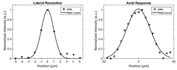
The SI-FLIM system was validated in multiple steps with both the FLIM and SIM components being validated independently. After both the components were tested, the system’s capability to measure the fluorescence lifetime with optical sectioning was evaluated. The lateral resolution of the system was tested using a line spread function and a Ronchi ruling. Taking the derivative of a “knife-edge” region, and measuring the FWHM yields a good approximation of the system lateral resolution [14]. The FOV was also measured using a Ronchi ruling. The axial response, or sectioning strength of the system, was measured by imaging a fluorescent layer of highlighter marker ink with ~15 µm thickness, verified by a confocal microscope with known axial resolution, 3-5 µm, as it was translated axially through the focus of the system. The average intensity of several pixels within individual SIM images was then plotted and fitted to a Gaussian to approximate the FWHM of the axial response. The theoretical lateral resolution is calculated by taking the spatial Nyquist sampling rate of the camera pixels (2-3 pixels) that are imaged into the sample plane. The theoretical axial response is calculated by evaluating the optical transfer function for the frequency of the grid pattern being used to modulate the illumination source [15]. The theoretical field of view is simply the sensor size imaged into the sample plane. Both the measured and theoretical values for field of view, lateral resolution, and axial response are shown in Table 1. Figure 2 shows the respective plots of the lateral resolution and the axial response with Gaussian estimations fitted to them.
Table 1. Field of view, lateral resolution, and axial response (theoretical and measured).
| Theoretical (μm) | Measured (mean/st.dev 5 samples) (μm) | |
|---|---|---|
| FOV | 900 | 902 |
| Lateral resolution | 1.86-2.79 | 2.02/0.14 |
| Axial response | 32.12 | 34.53/1.07 |
Fig. 2.
(A) Lateral resolution plot from “knife-edge” Ronchi ruling with Gaussian fit. (B) Axial response plot generated by translating a fluorescent planar sample through focus and plotting SIM image pixel intensity with Gaussian fit.
3.2 Fluorescent standard validation
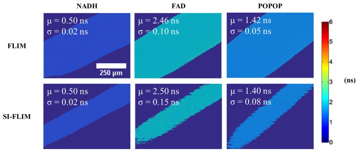
SI-FLIM images were compared to standard wide-field FLIM images that were acquired using the same system by switching all of the DMD mirrors to the on position. The lifetime values as observed in literature and the average lifetime values as measured by wide-field FLIM and SI-FLIM are listed in Table 2. Figure 3 shows representative images of each fluorophore for both FLIM and SI-FLIM where each image is taken from a 5 image set. The mean and standard deviation across each of the images in Fig. 3 is shown as an overlay. The measurements for Table 2 are taken as the average and standard error of the mean lifetime values over the FOV for five images of the same sample. The capillary tubes in Fig. 3 appear to be different sizes, however, this is a result of optical sectioning. Only the portion seen in the SI-FLIM sections is in focus. The wide-field FLIM tubes that appear larger have more measured fluorescence from the out-of-focus planes. Because these tubes contain homogenous solutions, the out-of-focus or background fluorescence does not significantly alter the measured lifetime. For validation purposes, our reported values consist of the mean of the means for five measurements and the standard error of the mean. This data helps show that the system can make repeatable and reliable fluorescence lifetime measurements. This is shown by the small standard errors, signifying our imaging system was able to maintain very good accuracy when repeating measurements. The variability within a homogenous fluorophore sample, such as the one shown in Fig. 3, is low at acceptable signal levels. The standard deviations for wide-field FLIM images ranges from 0.01 to 0.1 ns and 0.01-0.2 for SI-FLIM images. This is fairly typical and is controlled mainly by the gain being used on the ICCD and the gate width to life time ratio, but also by the contrast of the grid pattern in the sample for SI-FLIM. The noise in SI-FLIM is generally larger and is an inherent property of SIM when compared to wide-field imaging. Using the average of the standard deviation values above, 0.05 for wide-field FLIM and 0.1 for SI-FLIM, we define our temporal resolution to be +/− one standard deviation, thus giving 0.1 ns and 0.2 ns, respectively.
Table 2. Wide-field FLIM and SI-FLIM lifetimes in quartz capillary tubes (theoretical and measured means and standard error values for 5 samples).
| FLIM |
SI-FLIM |
||
|---|---|---|---|
| Literature (ns) | Measured (mean/std. error 5 samples) (ns) | ||
| NADH | 0.4-0.5 | 0.50/0.001 | 0.50/0.004 |
| FAD | 2-3 | 2.46/0.004 | 2.52/0.011 |
| POPOP | 1.2-1.4 | 1.43/0.004 | 1.39/0.013 |
Fig. 3.
FLIM and SI-FLIM image comparison, color bar in nanoseconds. The capillary tubes in the SI-FLIM images appear to be smaller; however, this is a result of optical sectioning rejecting the out of focus blur that contributes to a larger perceived size in the wide-field FLIM images. Only the portion of the tube seen in the SI-FLIM images is actually in focus.
3.3 Stacked two layer fluorescent model
Two layer phantoms were used to demonstrate that SI-FLIM can measure the lifetimes of spectrally and spatially overlapping fluorophores that are separated along the axial dimension. Phantoms were created by stacking 50 μm diameter capillary tubes to produce two layers. The top layer tube was filled with either NADH or FAD to simulate the biochemical makeup of oral epithelium, and a bottom layer tube was filled with POPOP to approximate the spectral properties of the collagen-containing lamina propria. A second empty capillary tube in the bottom layer used as a support to keep the planes of the top and bottom tubes parallel. The tubes were arranged in a cross pattern so that each layer was evenly supported and parallel with the imaging plane. Figure 4 shows a 3D representation of the phantom construction. The inner diameter of the tubes is 50 µm and the outer diameter is 80 µm to ensure that the center-to-center spacing of the tubes in the axial imaging dimension is ~80 µm.
Fig. 4.
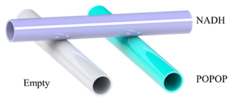
Schematic of the stacked capillary model. The top purple tube represents NADH/FAD and the bottom teal tube represents POPOP.
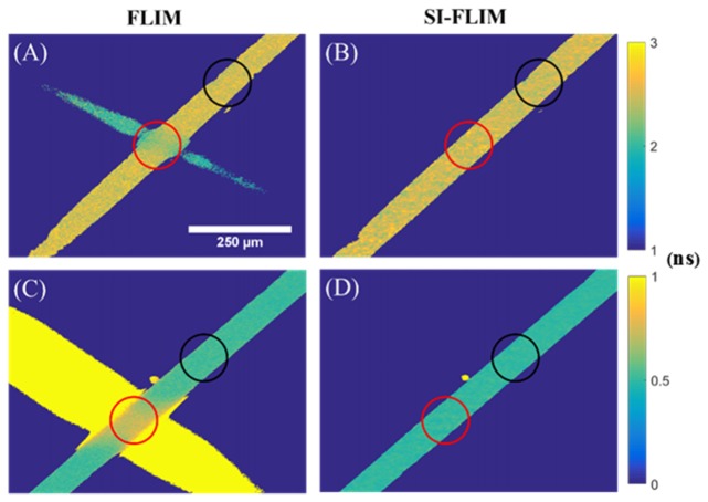
The phantoms were tested by focusing on the center of the top capillary tube which contained either NADH or FAD. The stack was imaged with both wide-field FLIM and SI-FLIM. All sectioned images were compared against non-sectioned FLIM to show that the stacked capillary tube phantoms reduce the measurement accuracy considerably if no sectioning is used. To quantitatively compare sectioning versus non-sectioning, the region of tube overlap where FAD/NADH are being imaged over the top of POPOP is compared against the areas of the image where there is no overlap. Table 3 summarizes the values measured and includes measurements of the average lifetime of NADH, FAD, and POPOP in single layer phantoms as well as the average lifetime measurements for NADH, FAD, and POPOP in the multi layered phantoms. The single layer measurements are referring to both the literature values and the measurements in Fig. 5 where the tubes do not overlap, whereas the double layer measurements refer to the areas of overlap. The five measurements used in computing the mean and standard error are five repeated measurements of the same sample. Figure 5 shows both top down views of the optical phantoms focused on the center of the top capillary tubes. The lifetime data summary for Fig. 5 is shown in Table 3 and the percent error summary is shown in Table 4. Equation (5) defines the percent error term used in Table 4.
Table 3. Comparison of wide-field FLIM and SI-FLIM measurements from overlaid quartz capillary tubes containing NADH or FAD in the foreground and POPOP in the background.
| Overlapping section (red circle) | Non overlapping section (black circle) | |||||
|---|---|---|---|---|---|---|
|
|
||||||
| FLIM | SI-FLIM | FLIM | SI-FLIM | |||
|
| ||||||
| Literature (ns) | Measured (mean/std. error 5 samples) (ns) | |||||
| NADH POPOP |
0.4-0.5 1.2-1.4 |
0.74/0.004 | 0.50/0.005 | 0.53/0.004 | 0.50/0.004 | |
| FAD POPOP |
2-3 1.2-1.4 |
2.39/0.025 | 2.50/0.010 | 2.49/0.017 | 2.48/0.013 | |
Fig. 5.
Top down view of optical phantoms with focus positioned at the middle of the top capillary tube. Top row: FAD overlaid on top of POPOP imaged with (A) wide-field FLIM and (B) SI-FLIM. POPOP is teal in A and B while FAD is orange-yellow. Bottom row: NADH overlaid on top of POPOP imaged with (C) wide-field FLIM and (D) SI-FLIM. POPOP is yellow for C and D while NADH is teal. The color bar for A and B is adjacent to B while the color bar for C and D is adjacent to D. Both color bars are in nanoseconds. Red circles indicate the region of capillary tube overlap that is measured while black circles represent the area of the capillary tubes without overlap that is measured.
Table 4. Percent Error between expected lifetime values with no overlapping fluorophore intensities and lifetime values with overlapping fluorophore intensities.
| FLIM | SI-FLIM | |
|---|---|---|
|
|
||
| Percent Error | ||
| NADH POPOP | 38.8 | 0.64 |
| FAD POPOP | 4.22 | 0.71 |
| (5) |
Because the lifetime of collagen, ranging from 3 ns or greater, is generally longer than that of either NADH or FAD, we expect SI-FLIM to create a net decrease on the measured lifetimes of NADH and FAD in the epithelium in comparison to wide-field FLIM [16]. However, because POPOP’s lifetime is between NADH’s and FAD’s lifetimes, we expect the lifetime for the overlapping section of NADH and POPOP to be > 0.5 ns and the overlapping region of FAD and POPOP < 2.5 ns. Figure 5 shows the effects of these overlapping fluorophores. The red circles in the figure indicate the region of overlap between the POPOP capillary tubes on the bottom and the NADH or FAD capillary tubes on the top. The black circles indicate a region with no overlap and should consist of only a homogenous fluorescence signal. The lifetimes from each region, black and red, were averaged and compared to one another. The percent error for wide-field FLIM images in Table 4 shows that the red circles had a significant difference from the expected lifetime values obtained from the black circles. When looking at the SI-FLIM images, there was very little error between the lifetimes within the black and red circled regions, thus indicating that the method is successfully rejecting the out of focus light and minimizing effects on lifetime.
3.4 Ex vivo tissue validation
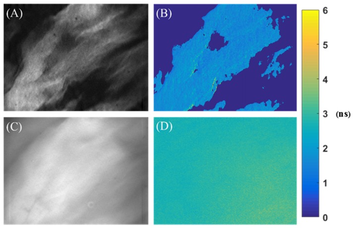
Ex vivo hamster check pouch mucosa preserved in formalin was imaged to show the efficacy of the method in tissue. Ex vivo imaging was performed to show that SI-FLIM can mitigate the effects of collagen in the lamina propria on the measured lifetime of NADH and, to a lesser extent, FAD in the oral epithelium. As predicted, the average lifetime for the NADH channel in the hamster cheek decreased when sectioning was used, which is attributed to the rejection of the collagen signal. It should be noted that the emission filter for these lifetime measurements was changed to a filter with the same 450 nm center wavelength but a broader 65 nm bandwidth (HQ450/65M, Chroma). This was done to increase our signal level while still maintaining a similar spectral band. A series of five SI-FLIM and wide-field FLIM images were taken at five different locations and compared to verify that the collagen rejection effect can be observed at many different locations. Figure 6 shows the effects of sectioning on the ex vivo hamster cheek pouch oral epithelium for the NADH spectral window. A non-parametric Wilcoxon rank sum test was used to verify that the SI-FLIM images and wide-field FLIM images are from statistically different (p < 0.008) populations. For each measurement, FLIM and SI-FLIM, five different locations were imaged. The mean lifetime/standard error for FLIM was 2.76/0.05 ns and for SI-FLIM it was 1.70/0.13 ns. Although we did not validate our system in a scattering phantom, results from our ex vivo experiments indicate that SI-FLIM should provide meaningful information in scattering samples such as tissue.
Fig. 6.
Optical images of 450 nm spectral channel (targeting NADH) in preserved ex vivo hamster cheek pouch oral epithelium. (A) Sectioned image used as the first gate for the lifetime image in B. (B) SI-FLIM map of hamster cheek pouch. (C) Wide-field image used as the first gate for the lifetime image in D. (D) Wide-field FLIM map of hamster cheek pouch. As expected, the lifetime for the sectioned map is less than the wide-field map indicating removal of submucosa collagen fluorescence.
At 355 nm excitation, collagen has a notable overlap in its emission spectra with NADH. This can potentially confound and reduce one’s ability to accurately resolve the fluorescence lifetime of NADH [4, 17]. Optical sectioning techniques that can remove the influence of the spectral overlap via spatial separation would theoretically be able to improve the accuracy of the NADH lifetime measurements. Both Fig. 6 and Table 4 show that SI-FLIM has the effect of lowering the measured lifetime in the NADH (450 nm) channel. This was the predicted effect optical sectioning was expected to have due to NADH possessing a much shorter lifetime than that of collagen [3, 18]. This theory is also supported by the data shown in Fig. 5 and Tables 3 and 4 where the effects of NADH overlaid on POPOP, a collagen substitute, are minimized and it is shown that the NADH lifetime is completely recovered without any influence from POPOP. This phenomenon can potentially be utilized to enhance the sensitivity of in vivo lifetime imaging systems for cancer diagnostics where the fluorescence signal from the collagen autofluorescence may dominate the NADH channel and reduce the ability to accurately measure the change in NADH lifetime [18]. Our technique has the potential to enable resolution of relatively small changes in NADH lifetimes in epithelial tissue by removing the effects of collagen on NADH. This increased ability to detect more minute changes in NADH lifetimes could lead to the ability to detect pre-cancerous tissue earlier and may also allow to differentiate between benign and malignant tissue.
In addition to collagen, keratinized epithelial tissue presents a similar challenge [19]. Keratin has a fairly large spectral overlap with NADH fluorescence lifetime similar to that of collagen, which can also confound the NADH measurement and reduce accuracy [17, 20]. Unlike collagen, the keratinized epithelium is superficial to the NADH containing epithelium. By using SI-FLIM, it may also be possible to image a section of the epithelial tissue that rejects the fluorescence signal from the keratinized epithelium superficial to it as well as the collagen containing connective tissue below it, leaving only fluorescence from the epithelium that contains NADH. This is supported by the observation of background rejection using structured illumination and by considering the symmetrical shape of the axial response function.
4. Summary
We have shown that SI-FLIM can produce accurate lifetime measurements in homogenous samples as well as in multi-layered phantoms where each layer has spectrally overlapping fluorophores. In addition to demonstrating SI-FLIM’s ability to accurately reconstruct lifetimes in three dimensions, we demonstrated that it greatly reduced the effects of the collagen/POPOP that confounds the measurements of NADH and FAD’s lifetimes in oral epithelium. Being able to measure these fluorophores independently is of great interest to those researching optical oral cancer detection. NADH and FAD are important metabolic cofactors that exist in either a protein bound state or free state where their fluorescence lifetime depends on the state [1, 21]. Tissue undergoing carcinogenesis has a marked change in the states of both FAD and NADH due to changes in cellular metabolism [11]. We believe that measuring these lifetimes without the influence of the collagen signal will potentially give the ability to create a significantly larger contrast between benign and malignant tissue. We are currently working to test our SI-FLIM system on hamster cheek pouch model of oral carcinogenesis in vivo.
Acknowledgment
This research was supported by National Institutes of Health (R01 CA138653, R03 CA191860). This work was also supported by NPRP grant # [8-1606-3-322] from the Qatar National Research Fund which is a member of Qatar Foundation. The statements made herein are solely the responsibility of the authors.
References and links
- 1.Lakowicz J. R., Szmacinski H., Nowaczyk K., Johnson M. L., “Fluorescence lifetime imaging of free and protein-bound NADH,” Proc. Natl. Acad. Sci. U.S.A. 89(4), 1271–1275 (1992). 10.1073/pnas.89.4.1271 [DOI] [PMC free article] [PubMed] [Google Scholar]
- 2.van Munster E. B., Gadella T. W. J., “Fluorescence Lifetime Imaging Microscopy,” Microscopy Techniques 95, 143–175 (2005). [DOI] [PubMed] [Google Scholar]
- 3.Cheng S., Rico-Jimenez J. J., Jabbour J., Malik B., Maitland K. C., Wright J., Cheng Y. -S., Jo J. A., “Flexible endoscope for continuous in vivo multispectral fluorescence lifetime imaging,” Opt. Lett. 38(9), 1515–1517 (2013). 10.1364/OL.38.001515 [DOI] [PMC free article] [PubMed] [Google Scholar]
- 4.Squire A., Bastiaens P. I., “Three dimensional image restoration in fluorescence lifetime imaging microscopy,” J. Microsc. 193(1), 36–49 (1999). 10.1046/j.1365-2818.1999.00427.x [DOI] [PubMed] [Google Scholar]
- 5.Sharman K. K., Periasamy A., Ashworth H., Demas J. N., “Error Analysis of the Rapid Lifetime Determination Method for Double-Exponential Decays and New Windowing Schemes,” Anal. Chem. 71(5), 947–952 (1999). 10.1021/ac981050d [DOI] [PubMed] [Google Scholar]
- 6.Cole M. J., Siegel J., Webb S. E. D., Jones R., Dowling K., Dayel M. J., Parsons Karavassilis D., French P. M. W., Lever M. J., Sucharov L. O. D., Neil M. A. A., Juskaitis R., Wilson T., “Time-domain whole-field fluorescence lifetime imaging with optical sectioning,” J. Microsc. 203(3), 246–257 (2001). 10.1046/j.1365-2818.2001.00894.x [DOI] [PubMed] [Google Scholar]
- 7.Bozinovic N., Ventalon C., Ford T., Mertz J., “Fluorescence endomicroscopy with structured illumination,” Opt. Express 16(11), 8016–8025 (2008). 10.1364/OE.16.008016 [DOI] [PubMed] [Google Scholar]
- 8.Moore C., Chan S. P., Demas J. N., DeGraff B. A., “Comparison of Methods for Rapid Evaluation of Lifetimes of Exponential Decays,” Appl. Spectrosc. 58(5), 603–607 (2004). 10.1366/000370204774103444 [DOI] [PubMed] [Google Scholar]
- 9.Hagen N., Gao L., Tkaczyk T. S., “Quantitative sectioning and noise analysis for structured illumination microscopy,” Opt. Express 20(1), 403–413 (2012). 10.1364/OE.20.000403 [DOI] [PMC free article] [PubMed] [Google Scholar]
- 10.Banerjee S., Bhatt D. K., “Histochemical studies on the distribution of certain dehydrogenases in squamous cell carcinoma of cheek,” Indian J. Cancer 26(1), 21–30 (1989). [PubMed] [Google Scholar]
- 11.Gulledge C. J., Dewhirst M. W., “Tumor oxygenation: a matter of supply and demand,” Anticancer Res. 16(2), 741–749 (1996). [PubMed] [Google Scholar]
- 12.Thomas P., Pande P., Clubb F., Adame J., Jo J. A., “Biochemical Imaging of Human Atherosclerotic Plaques with Fluorescence Lifetime Angioscopy,” Photochem. Photobiol. 86(3), 727–731 (2010). 10.1111/j.1751-1097.2010.00707.x [DOI] [PubMed] [Google Scholar]
- 13.Kristoffersen A. S., Erga S. R., Hamre B., Frette Ø., “Testing Fluorescence Lifetime Standards using Two-Photon Excitation and Time-Domain Instrumentation: Rhodamine B, Coumarin 6 and Lucifer Yellow,” J. Fluoresc. 24(4), 1015–1024 (2014). 10.1007/s10895-014-1368-1 [DOI] [PMC free article] [PubMed] [Google Scholar]
- 14.Smith S. W., The Scientist and Engineer's Guide to Digital Signal Processing (California Technical Publishing, 1997), p. 625. [Google Scholar]
- 15.Chasles F., Dubertret B., Boccara A. C., “Optimization and characterization of a structured illumination microscope,” Opt. Express 15(24), 16130–16140 (2007). 10.1364/OE.15.016130 [DOI] [PubMed] [Google Scholar]
- 16.Coda S., Thompson A. J., Kennedy G. T., Roche K. L., Ayaru L., Bansi D. S., Stamp G. W., Thillainayagam A. V., French P. M. W., Dunsby C., “Fluorescence lifetime spectroscopy of tissue autofluorescence in normal and diseased colon measured ex vivo using a fiber-optic probe,” Biomed. Opt. Express 5(2), 515–538 (2014). 10.1364/BOE.5.000515 [DOI] [PMC free article] [PubMed] [Google Scholar]
- 17.Zheng W., Wu Y., Li D., Qu J. Y., “Autofluorescence of epithelial tissue: single-photon versus two-photon excitation,” J. Biomed. Opt. 13, 054010 (2008). [DOI] [PubMed] [Google Scholar]
- 18.Cheng S., Cuenca R. M., Liu B., Malik B. H., Jabbour J. M., Maitland K. C., Wright J., Cheng Y.-S. L., Jo J. A., “Handheld multispectral fluorescence lifetime imaging system for in vivo applications,” Biomed. Opt. Express 5(3), 921–931 (2014). 10.1364/BOE.5.000921 [DOI] [PMC free article] [PubMed] [Google Scholar]
- 19.Pavlova I., Williams M., El-Naggar A., Richards-Kortum R., Gillenwater A., “Understanding the Biological Basis of Autofluorescence Imaging for Oral Cancer Detection: High-Resolution Fluorescence Microscopy in Viable Tissue,” Clin. Cancer Res. 14(8), 2396–2404 (2008). 10.1158/1078-0432.CCR-07-1609 [DOI] [PMC free article] [PubMed] [Google Scholar]
- 20.Wu Y., Qu J. Y., “Combined depth- and time-resolved autofluorescence spectroscopy of epithelial tissue,” Opt. Lett. 31(12), 1833–1835 (2006). 10.1364/OL.31.001833 [DOI] [PubMed] [Google Scholar]
- 21.Maeda-Yorita K., Aki K., “Effect of Nicotinamide Adenine Dinucleotide on the Oxidation-Reduction Potentials of Lipoamide Dehydrogenase from Pig Heart,” J. Biochem. 96(3), 683–690 (1984). [DOI] [PubMed] [Google Scholar]


