Abstract
Robotic needle steering will improve percutaneous radio-frequency ablation (RFA) in the liver by performing distributed ablations without requiring multiple punctures of the liver capsule, thus enabling the treatment of large or multifocal tumors. However, state-of-the-art asymmetric-tip robotic needle steering systems do not yet achieve clinically relevant curvature. This work presents the design and development of a highly articulated needle that enables distributed RFA in liver tissue under ultrasound (US) image guidance. Our new needle design attains the target curvature required for liver procedures while meeting important clinical requirements, such as the use of fixed diameter needle introducers, presence of a free needle working channel, robustness for repeated insertions, and conductivity for the delivery of RF current for tissue ablation. The new needle tip includes two important design features: A tendon-actuated Nitinol asymmetric flexure joint, which allows for an active amplification of the needle steering force, and a steel back-bevel tip profile, which decreases the risk of needle jamming. The needle’s resulting curvature was evaluated in both phantom and ex vivo liver tissues using segmented US images. The average radius of minimum curvature in ex vivo liver tissue was found to be 33.6 mm, the smallest reported to date. Furthermore, RFA in ex vivo porcine liver tissue tests were performed to demonstrate that distributedablation with a single puncture of the liver capsule is possible via robotic needle steering.
Index Terms: Medical robots and systems, surgical robotics: steerable catheters/needles
I. Introduction
A. Motivation
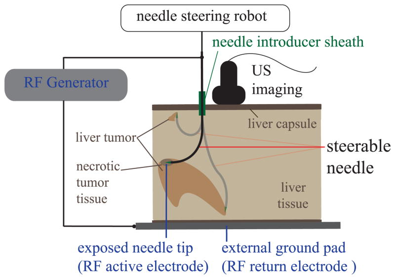
Hundreds of thousands of new cases of primary and metastatic liver cancer are diagnosed worldwide each year. Patient survival often depends on eradication of those tumors; while surgery has historically been considered the most effective option, still many patients are not surgical candidates because of tumor size, type, or location; inadequate liver reserve; or other co-morbidities [1]. Percutaneous radio-frequency ablation (RFA) is an effective, well-tolerated, minimally invasive treatment of liver cancer for such patients [2]. Percutaneous RFA procedures use electric current, delivered through tip of the needle, to destroy cancer cells with heat. Most existing RFA systems use straight, needle-like probes under ultrasound or computed tomography (CT) guidance [3]. Unfortunately, the use of RFA is limited to small, isolated tumors because of the high risk of bleeding that comes from puncturing the liver capsule multiple times [2]. For this reason, just 12% of hepatocellular carcinoma patients and a smaller fraction of patients with liver metastases are currently eligible for RFA treatment [4]. We propose that robotic needle steering will enable tissue ablations in multiple locations of the liver (distributed ablation) with one puncture of the liver capsule (Fig. 1). With this technique, a flexible needle is inserted through a single access point and then guided along controlled curved paths within the tissue [5]. This approach would potentially enable destruction of large and multifocal liver tumors (Fig. 1), significantly increasing the number of patients that can be effectively treated via this minimally invasive approach.
Fig. 1.
Percutaneous radio-frequency ablation (RFA) of liver tissue via needle steering using ultrasound (US) imaging (overview scheme of the system). The needle is steered to several locations in the liver under ultrasound guidance from a single puncture site. RF current is passed from the RF generator through the needle and heating occurs at the needle tip. Needle steerability is important for both the reachable liver workspace from a single insertion site and shaped ablations of irregular tumors.
B. Background
Several methods for achieving controlled deflections of a needle have been described in literature [6]. DiMaio and Salcudean [7] demonstrated small deflections of a needle from a straight line path through manipulation of the needle’s base. Alternatively, the needle can be steered by manipulating the tissue surrounding the needle itself [8], [9]. Concentric tube robots can act as steerable needles when controlled in a follow-the-leader manner [10], [11]. These robots use overlapping pre-curved sections of flexible tubes that can be progressively advanced with respect to one another to achieve steering behavior in free space. Burdette et al. [12] integrated a concentric tube robot with an ultrasonic ablator. Preliminary ex vivo tests were performed with the device, which demonstrated the possibility of ablating a large volume of tissue with a single puncture to the liver perenchymia. However, concentric tube robots typically exceed the maximum size (15 gauge, or more than 1.8 mm outer diameter) that is clinically desirable for percutaneous RFA in the liver [13].
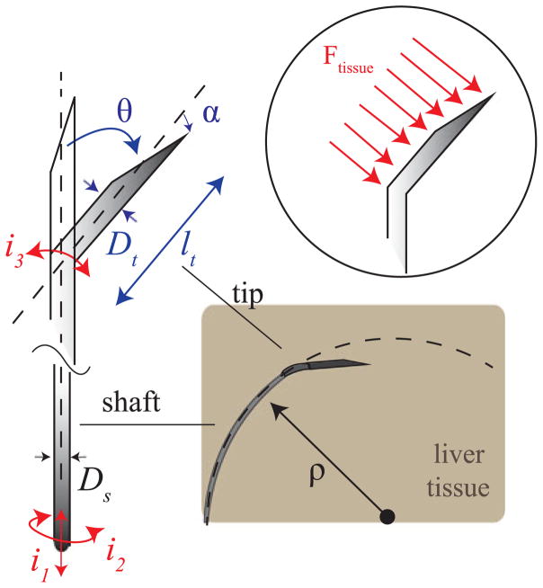
In this work we focus on an alternative approach, which uses an asymmetric needle tip and relies on interaction with tissue to steer the needle. As the needle is inserted, tip asymmetry results in a net lateral force on the needle tip (Fig. 2). The section of the needle shaft following the tip ideally follows a path with constant radius of curvature ρ. This steering technique uses two control inputs: insertion and rotation (spinning) of the needle base (i1 and i2 in Fig. 2). Although pure insertion leads to maximum curvature, curvature can be varied from maximum curvature to zero curvature via duty-cycle control [5]. Tip-steerable needle shafts are traditionally made of Nitinol, a super-elastic material [5]. Nitinol can withstand up to 8% strain before yield. This allows the needle shaft to curve tightly without permanently deforming inside the tissue. The needle material, shaft outer diameter, and shaft wall thickness determine the bending stiffness and torque transmission from the base to the tip of the needle. Tip asymmetries may consist of a bevel angle α and/or tip pre-bend angle θ (Fig. 2). Tip bevel angle plays an important role for tissue rupture and needle steering force [14], [15]. However, no significant effects in curvature were found by varying bevel angle in ex vivo tissue, as well as in in vivo tests [16]. We previously investigated the steerability of pre-bent tip steerable needles and found that bend angle, θ, and tip size parameters, l and Dt , play a significant role in the achievable curvatures (Fig. 2) [13]. Various needle curvatures have been reported in literature of pre-bent steerable needles in artificial phantom tissue: 67 mm [13], 121 mm [17], and 128 mm [18]. By experimenting with tip parameters θ and l, Adebar et al. achieved an average radius of curvature of 41.7 mm of pre-bent tip steerable needles in ex vivo liver tissue [13]. Others have reported 51.4 mm [16], 137 mm [17], 176 mm [19], 200 mm [20], and 400 mm [18]. In the only reported in vivo test, pre-bent tip steerable needles followed curved paths with radii of curvature from 104 mm to 143 mm in canine kidney and liver [20].
Fig. 2.
Asymmetric-tip needle steering working principle: during the needle insertion, tip asymmetry results in net lateral force Ftissue on the needle tip, which causes the needle shaft to bend along a curved path of radius ρ. The asymmetric tip may incorporate a bevel with angle α and a bent section defined by the angle θ, formed with the central needle axis, and the length lt . i1 , i2 , i3 are the inputs to the needle steering system (needle insertion, needle rotation and needle’s tip articulation angle).
The remainder of this letter is organized as follows: Section II firstly provides a description of the clinical challenges and the general approach of state-of-the-art solutions to increase the needle steering force; secondly the design requirements for an effective robotic needle steering system which enables percutaneous RFA of liver tumors are presented. Section III gives an overview of the needle steering robotic system used in this work; while Section IV focuses on the innovative design of the needle tip, describing the design choices and main features use to increase the steering force and avoid needle jamming in liver tissue. Section V presents needle curvature tests in both phantom tissue and ex vivo porcine liver tissue. Section VI describes a preliminary RFA test performed with the needle in ex vivo liver tissue. Finally, Section VII summarizes the contributions and gives directions for future work.
II. Problem Definition
A. Clinical Challenges
Although pre-bent needle tips have shown promise in terms of steerability, they can cause tissue damage when the bent section (l) is long and the needle is rotated around its axis, to change direction of insertion or during duty cycle control [3]. Swaney et al. attempted to minimize tissue damage by incorporating a passive flexure element into their needle design [19]. In addition to tissue damage, the pre-bent tip cause a relevant mismatch between the orientation of the tip and base of the needle, due to the torsional moment generated by the pre-bent tip during needle base rotation (i2) [21]. Additionally, percutaneous procedures, using asymmetric tip steering and a very flexible shaft, often require an introducer sheath in clinical practice. The introducer sheath is used to directly connect the steerable needle with the target organ. For the case of the liver, the first puncture in the capsule is created with a sharp and rigid stylet passed through the sheath lumen. Once the puncture is created, the stylet is retracted and replaced with the needle, as depicted in Fig. 1. This avoids damaging the flexible needle or altering the needle steering behavior due to the puncture of the liver capsule and previous tissue layers. The use of an introducer sheath, however, imposes constrains on the maximum needle diameter and the shape of the needle tip. A needle with a permanent pre-bent tip section cannot be passed through the introducer sheath.
B. General Approach: Active Needle Tip
An articulated needle tip, which allows active control of the tip bend angle, θ, into the tissue is a solution to the previously listed issues about the passage thought a straight introducer sheath. In addition, using an articulated tip provides another control input to the system: tip articulation angle (i3 in Fig. 2). Recently, several groups have developed articulated tip designs. Van de Berg et al. [6] demonstrated a conical steel tip which is controlled via four tendons routed to the tip of the needle. A simpler needle tip articulation is used by Adebar et al. in [13], where a small hinge is used to achieve rotation of a stainless steel needle tip relative to the needle shaft. In this case a single tendon is used to control the single degree of freedom at the tip which is combined with the needle rotation (i2 in Fig. 2). However, the use of a 3D printed hinge resulted in fragility for tip lengths over 10 mm, so the resulting radius of curvature of the needle at the maximum tip articulation was 82 mm. Additionally, the use of a hinge structure with multiple components, such as joints and pins, represents an impediment for RF current delivery through the needle tip and, also, occupies the free needle working channel. Motivated by the problems related to hinge-like designs, we investigated continuous structures involving flexure joints. Several groups built miniaturized single degree-of-freedom wrists for minimally invasive surgical application by simply creating a pattern of cuts in Nitinol tubes in order to create compliant regions for bending [22]–[24]. Our design resembles the approach of Ryu et al. [25], who used a pattern of laser cut notches on a Nitinol tube attached to a steerable needle for prostate-biopsy interventions. However, the heat-activated SMA wire used to generate bending of the Nitinol tube only resulted in 10° of deflection of the tip articulation. Such tip angle, however, does not generate sufficient needle curvature for reaching distributed ablations in liver tissue.
C. Design Requirements
In order to develop an effective system for needle steering and RFA in the liver, the following fundamental design requirements were defined based on previous works:
The tip articulation angle must be actively controlled to enable the passage into needle introducers employed in clinical practice [13]. The use of a 15 gauge needle introducer, for example, translates to a maximum needle tip diameter (Dt ) being less than 1.4 mm in a straight configuration.
According to [13], in order to determine an acceptable needle curvature in liver tissue, the maximum tip articulation angle (θa ), must range from 40° to 60° (at maximum); while the tip length, after the articulation lt , must be larger than 12 mm.
The bevel angle, α, must be less than 20° to ensure a sharp contact with the tissue and effectively initiate the needle curvature [10].
A conductive path must be provided from the needle shaft to the tip for appropriate RF current delivery.
The needle must have a free working channel for possible sensor integration or to allow the passage of adjuvant fluids (e.g. saline solution) for the ablation process.
III. System Overview
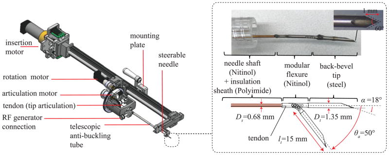
The robotic needle steering platform for RFA of liver tumors used in this work is shown in Fig. 3 [13]. The core of the system is the steerable needle, whose tip (shown in detail in the inset of Fig. 3) has been designed by following the requirements defined in Section II-C. The control of the steerable needle is managed by the robotic platform positioned at the base of the needle. As described in [13], the platform consists of three motors, each controlling one of the three system input summarized in Fig. 2 (i1 : needle insertion, i2 : needle rotation, and i3 : tip articulation). Before entering the tissue, the needle is protected by an anti-buckling telescopic tube. In addition, the system is integrated with a connection to the RF current generator which manages the engagement (i.e. short circuit) of the RF active electrode with the shaft needle shaft. To ensure that the delivery of RF current is perfomed only through the needle tip, an insulation flexible sheath is used to cover the needle shaft (visible in the inset of Fig. 3). This sheath is made of Polyimide, an insulation material which is lightweight, flexible, and resistant to heat.
Fig. 3.
Overview of the robotic needle steering platform. Inset : Magnified view of the needle tip.
IV. Articulated Needle Tip Design
The needle tip consists of two metallic tube sections which are fixed at the end of the needle shaft and form a short circuit with it. The first is a Nitinol tube which incorporates a tendon actuated articulation that is able to produce a total deflection of 50° in one direction. The second, and most distal, section is a stainless steel tube featuring a bevel angle of 18° and a back bevel profile. With this structure,the needle tip has a total length of 20 mm (Fig. 3), which is also the length of exposed needle during RF current delivery. The implementation of this new needle tip is enabled by the use of ultra-violet (UV) laser cutter-based manufacturing of small diameter metallic tubes. The use of lasers in metal manufacturing is increasingly popular, due to their high processing speeds and flexibility over more traditional computer numerical control (CNC) milling and wire electro-discharge machining (EDM) [22]. Q-switched and ultra-short pulsed lasers, in particular, offer very small tolerances (0.025 mm) for cutting of metals by creating a very small heat affected zone (HAZ) [26]. This enables the creation of complex features in small size components with materials such as Nitinol, which are very susceptible to temperature [27]. In this work a fixed-stage UV laser cutter (Series 3500 UV Laser, DPSS Laser Inc., Santa Clara, CA, USA) has been used for manufacturing the feature of both the tip sections (Nitinol articulation and stainless steel back bevel tip).
A. Active Tip Articulation: Nitinol Modular Flexure
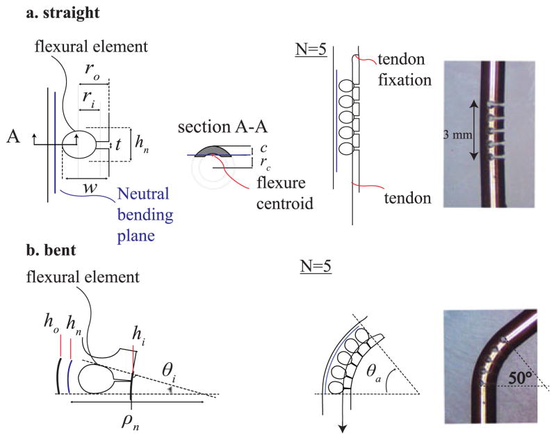
The active tip articulation mechanism uses multiple flexural elements (Fig. 4) that allow the tip to bend when it is pulled by a tendon to a maximum angle, θa . This mechanism is designed to be much stiffer than the surrounding tissue, so that it can both fully straighten when the tendon is released and maintain the desired articulation angle as the needle is inserted. A single element consists of an asymmetric laser-cut notch (Fig. 4(a)) and has three fundamental geometrical parameters: hn , the total height of the notch, w, the depth of the notch, and t, the height of the open side of the notch. The geometry of the notch profile is designed to limit the strain of the material to values that are within Nitinol yield tolerance. This constraint determines the maximum angle allowed for each flexural element. To determine this angle, we analyzed the bending deformation of a single notch section on the plane perpendicular to the cut (see scheme of Fig. 4(a) and (b)). The maximum deformation in tension at the outermost point (ho ) from the neutral bending plane is:
| (1) |
where hn (height of the notch) represents a section of neutral bending plane that, for definition, does not experience any deformation during bending. Using classing bending beam theory, the maximum deformation in tension (εmax) may be expressed as
Fig. 4.
Tendon actuated tip articulation composed by a Nitinol modular flexure. (a) Straight configuration and single flexural element parameters. (b) Bent configuration and single flexural element parameters.
| (2) |
where ρn is the radius of curvature formed by the neutral bending plane while c = ro − rc represents the maximum outer distance from the neutral bending plane. As shown by section A-A of Fig. 4(a), the neutral bending plane of the flexure is identified by the position of the section centroid rc .
To prevent plastic deformation εmax must be limited to 8%, which correspond to Nitinol maximum deformation before yield [28]. We limited it to 5% to add an additional 1.6 safety factor. Equation (2) gives the maximum angle each element can subtend, θi :
| (3) |
For our tube geometry, we found that a flexural element height of 0.6 mm (hn ) determines a maximum bending angle for each module to be around 10°. Hence, in order to achieve an articulation angle of 50° (θa), N = 5 elements must be used to bend a 3 mm segment of UV laser cut Nitinol tube having an inner and outer diameter of 0.7 mm and 1.16 mm, respectively (Fig. 4(a)). The design of the notch profile also includes a distance t, which prevents the flexure from deforming past εmax. t can be found using the difference of hn and hi :
| (4) |
where hi is defined as
| (5) |
By substituting Equation (5) in Equation (4) and using the given parameter values, t was set to 0.2 mm for our articulation design.
B. Back-Bevel Steel Tip
Unlike the rest of the needle, the needle tip cutting surface must be very stiff and sharp. For this reason, the last section of the needle tip is made from stainless steel (Fig. 3) and present a back-bevel profile in order to maximize needle tip sharpness [29]. The back-bevel profile consists of a double cut on the plane perpendicular to the primary bevel cut. In this work, we used a back bevel angle of 60° and a length of 1 mm (inset picture of Fig. 3). Once the tissue has been cut and penetrated by the back-bevel tip, it is desirable to maximize contact surface area with the tissue in order to generate the steering force needed to curve the needle shaft. For this reason, we our design has a wider diameter tip (Dt ) than the rest of the shaft (Ds ) (Fig. 3). In particular, Ds = 0.68 mm and Dt = 1.35 mm, so that Dt /Ds ≈ 2. This allows for the implementation of the airfoil effect described in [30] but using a Nitinol tube and not simply a wire. Note that Dt has also the upper-bound limit due to the size of the needle introducer.
V. Needle Curvature Tests
A. Methods
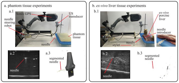
Fig. 5 shows the experimental set up that was used for testing in both phantom tissue and ex vivo porcine liver tissue. A block (30 × 30 × 5 cm) of Polyvinyl Chloride (PVC) was used as artificial tissue (Fig. 5(a)). PVC has been shown to be a suitable and widely used material for needle insertion research in soft tissue because of its optical transparency and appropriate mechanical properties [31]. For the ex vivo test, four separate porcine livers, obtained fresh from a butcher, were tested with the same needle. During needle insertion in the ex vivo tissue, a 15 gauge introducer sheath and a stylet were used to puncture the liver capsule and provide a channel for the needle to directly access the liver tissue (Fig. 5(b.1). In both artificial tissue and ex-vivo porcine tissue, a different insertion point was chosen before each repetition to avoid the needle erroneously following previous tracks. The needle was inserted at a constant insertion velocity (2 mm/s) using the needle steering robot described in [13] for a fixed distance (100 mm), or until the needle exited the liver. All the tests were started by inserting the needle tip into the tissue in a straight configuration to replicate a clinical scenario. Once the tip was completely inserted, the needle tip articulation was moved to the specific test angle θa and the needle insertion started. After each insertion was completed, the tissue specimen with the articulated needle inside was scanned using freehand 3D ultrasound imaging.
Fig. 5.
Experimental apparatus used for testing the needle in (a) phantom tissue and (b) ex vivo liver tissue. (a.1) Overview of the setup for tests in phantom tissue. (a.2) 2D ultrasound image used for needle segmentation. (a.3) Needle curvature measurement using 3D ultrasound data. (b.1) Overview of the setup for tests in ex vivo liver tissue (includes magnified view of the needle introducer). (b.2) 2D ultrasound image used for needle segmentation. (b.3) Needle curvature measurement using 3D ultrasound data.
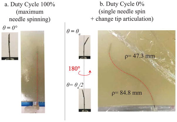
A Sonix MDP ultrasound system (Analogic Corp., Peabody, MA, USA) with linear transducer was used to image the needle. The system includes a calibrated electromagnetic tracking system (Sonix GPS), which monitor the orientation of the probe and enables the collection of 3D ultrasound data of the environment [32]. To measure the needle curvature, the needle was segmented by manually localizing the needle cross-section in the set of serial 2D US image frames captured for each needle insertion. This process is depicted for the tests in phantom tissue and ex vivo liver tissue in Fig. 5(a.2) and (a.3) and Fig. 5(b.2) and (b.3). This manual segmentation is repeatable to within 0.5 mm [32]. Since the needle is never rotated around its axis during insertion, the needle path into the tissue can be approximated to lie on a 2D plane. Therefore, the 3D segmented points are projected onto a 2D plane of best fit using principal component analysis. Then a circular arc is fit to the segmented data using a least squares method, whose radius is used as the radius of curvature. Three discrete angles of tip articulation angles were tested using 0% duty cycle (corresponding to maximum curvature for a given angle of tip articulation). For each needle tip articulation amount, 8 insertions were done in artificial tissue and 5 in ex vivo tissue. Two supplementary tests were performed in artificial tissue to confirm the ability to guide the needle along paths with different direction of insertions and curvatures by varying both articulation angle and duty cycle ratio. In particular, a straight path insertion (100% duty cycle ratio and straight articulation, Fig. 7(a)) and an s-shape insertion (two pure insertions with two different articulation angle, with a 180° of needle rotation in between, Fig. 7(b)) were performed. During s-shape insertions, the tip articulation was set to 0° before the needle was turned.
Fig. 7.
Duty cycling and s-shape demonstration in phantom tissue. (a) Insertion with 100% duty cycle and θa = 0. (b) A multiple curvature path is achieved using two different articulation angles and rotating the needle 180° in between.
B. Results and Discussion
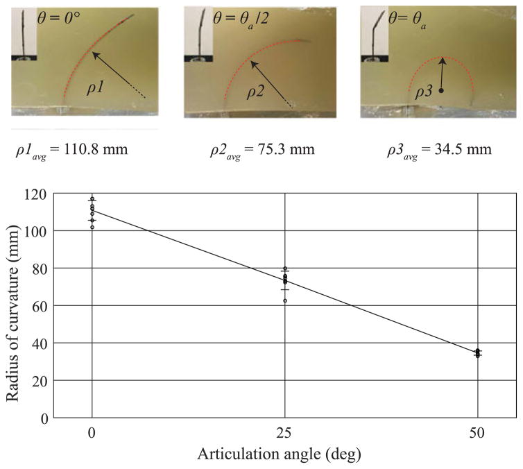
Fig. 6 summarizes the measured radius of curvature as a function of the tip articulation angle in artificial tissue with no needle turning. The radius of curvature ρavg (mean ± standard deviation) spans from a maximum value of 110.8 ± 5.3 mm (no articulation, θ = 0°) to a minimum value of 34.5 ± 1.2 mm (maximum tip articulation θ = θa). As mentioned before, every test was initiated with the needle tip completely inserted into the tissue in a straight configuration. For this reason, the segmented data was collected after the initial straight portion of the needle’s path.
Fig. 6.
Articulation angle tests in phantom tissue. (a) Summary of experimental measurement of the radius of curvature in phantom tissue during insertion with no needle rotation. Three tip angles were tested (for ten repetitions): θ = 0°, θ= θa/2 (25°), and θ = θa (50°). The graph reports actual values and mean value ± standard deviation: ρ1 =110.8 ± 5.3 mm, ρ2 =73.3 ± 4.9 mm, ρ3 =34.5 ± 1.2 mm. The dotted red line superimposed on the needle in the pictures represents the section of needle path used for estimating the radius of curvature.
With 100% duty cycle, the needle performs a linear straight path from the insertion point with very minimal spatial deviation from the straight line, as shown in Fig. 7(a). The maximum measured deviation from the straight line was evaluated around 1.5 mm. The s-shape path is shown in Fig. 7(b). In this case the needle followed two curved paths, having radii of curvatures of 84.8 mm and 47.3 mm, respectively. These values are both in accordance with the radius reported in Fig. 6.
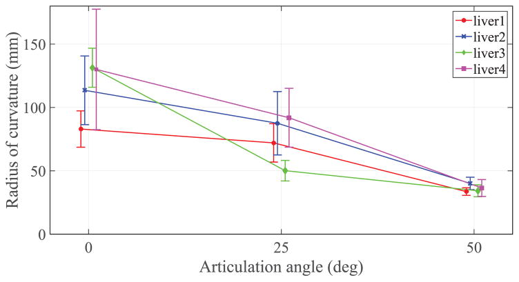
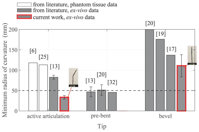
Fig. 8 summarizes the radius of curvatures evaluated during the ex vivo test on four different livers for the same three articulation angles. Particularly relevant is the minimum radius of curvature at the maximum tip articulation which, for liver 1, reached an value of 33.6 ± 2.9 mm. The values of the minimum radius of curvature at maximum tip articulation (θa = 50°) in liver tissue exhibit very little variance between different livers and less variability within the same liver specimen, showing promising results in terms of reliability and repeatability of the needle steering process for tight needle curvatures. More variability is registered in the results related to the insertions with no articulation (θa = 0°) where the variance is larger. Fig. 9 compares the mean radius of curvature obtained in this work in ex vivo liver tissue with other steerable needle systems reported in literature. The three main categories of tip-based needle steering techniques (bevel tips, pre-bent tips, and articulated tips) are considered and the most recent studies in the state-of-the-art are reported in terms of first author and year of publication. The threshold of 50 mm (dotted line in Fig. 9) represents the reference value of radius of curvature needed to access the majority of the human liver from a single insertion site [33]. To verify that the new needle design achieves a radius of curvature that is significantly lower than the threshold for liver application (50 mm), we performed a hypothesis test (one-sided t-test) using all the radius of curvature measures in the case of maximum articulation (θa = 50°) performed in ex vivo liver tissue. This test assumes the radius of curvature values are normally distributed, which was a reasonable approximation for the collected data. The improvement in steering force generation due to the new needle tip design may also be seen from the comparison between the current needle with no articulation (θa = 0°) and state-of-the-art bevel tip needles. In this case, the effect of an airfoil back-bevel tip is reflected in the resulting high needle curvature over standard bevel tip designs and no important buckling events experienced during all the insertions.
Fig. 8.
Summary of the ex vivo tests on four porcine livers. Three tip angles were tested (for 5 repetitions for each liver) at 0% duty cycle: θ = 0°, θ= θa/2 (25°), and θ= θa (50°). The graph reports the mean ± standard deviation of the data.
Fig. 9.
Comparison of current results with the state-of-the-art needle steering systems. The bar height reports the minimum average radius of curvature and the standard deviation (when available). Current work results (red-border bars) report the mean value and standard deviation considering the total number of trials of the ex vivo tests (5 insertions at the maximum articulation for 4 livers). The p-value from the one-sided t-test to determine whether the measured radii of curvatures were significantly lower than 50 mm was found to be less than 0.0001 (p < 0.0001).
VI. Distributed Ablation in Liver Tissue
A. Methods
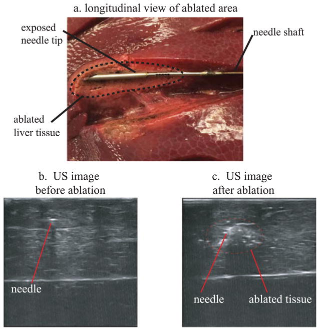
In addition to curvature tests, distributed ablation tests were performed to demonstrate the suitability of the robotic needle steering system for clinical RFA of liver tissue. The power and delivery time for the RF current were set up with the RF generator (model 1500, Rita Medical Systems Inc.). The active electrode was connected to the needle shaft with a custom designed mechanism, which maintains electrical contact between the needle and electrode (Fig. 3). A grounding pad was created by placing a piece of aluminum foil underneath the liver and connecting it to the return electrode of the RF generator. Ablation zones in the liver were created by using approximately 30 Watts of power for 2 minutes. The resulting effect of exposing the tissue to RF current delivered by the needle tip is shown in Fig. 10(a). Using US imaging, it was possible have a real time visualization of the ablation zone around the needle tip. Fig 10 proposes a comparison between two 2D US images of the needle before (Fig. 10(b)) and after (Fig. 10(c)) the RF ablation obtained by the US tracking imaging system. Fig. 10(c) shows how the echogenity of the tissue around the needle is considerably increased after ablation.
Fig. 10.
(a) Picture of the ablated tissue profile around the needle tip (longitudinal profile). (b)–(c) Comparison between two US images of the needle tip having the US probe oriented in the needle tip transverse plane: before (b) and after (c) the delivery of the RF current from the tip needle.
B. Results and Discussion
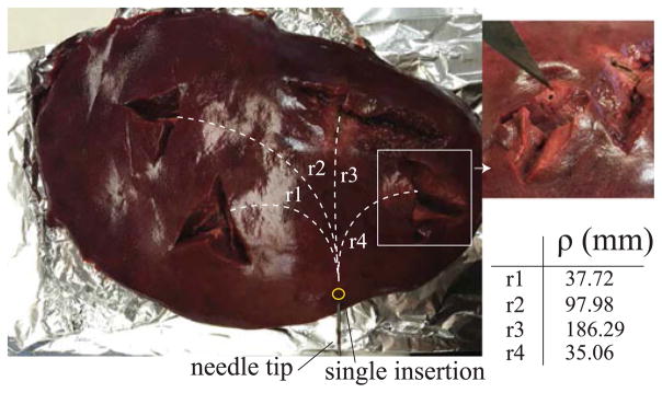
An example of distributed ablation of liver tissue using a single puncture in the liver capsule is shown in Fig. 11. For each ablation, the curvature of the needle was determined using the US tracking system. The table in Fig. 11 reports the values related to the radius of curvature of the needle path to perform the relative ablation shown in the picture of Fig. 11. These preliminary results demonstrated that with a single puncture to the liver capsule, it is possible to reach and effectively ablate multiple locations of the liver which require highly curved paths from the same insertion point.
Fig. 11.
Distributed ablation in the liver. Four insertions with different needle tip configurations were performed using a single access point for the needle. After each insertion, the needle was scanned with the US imaging system to measure the radius of curvature ρ.
VII. Conclusion
In this work, we examined the problem of performing distributed percutaneous ablation in the liver using a steerable needle. The main objective was to facilitate ablation of different areas of the liver by using a single puncture through the liver capsule. We described and tested a new design for our steerable need robot, that satisfies both the clinical requirements for RFA in the liver and achieved very small radius of curvatures, especially in ex vivo liver tissue.
This work incorporates key elements from several previous designs in the state-of-the-art of steerable needles, such as the use of a back bevel needle tip profile and an active tip articulation, which adds a degree-of-freedom to the system. These elements maximize lateral force generation on the needle tip and thus the needle curvature. The results of the curvature tests showed that the needle can reliably achieve a radius of curvature that is less than the clinically required 50 mm in ex vivo tissue. The new needle was also used to perform RFA in ex vivo liver tissue, demonstrating the possibility to ablate different regions of the same liver using a single liver capsule puncture, thus a single needle entry point. Future work, will focus on US-guided closed loop control of the steerable needle in in vivo porcine model for RFA of liver tumors.
Acknowledgments
This work was supported by the National Institutes of Health through R01 EB018849.
Footnotes
Color versions of one or more of the figures in this letter are available online at http://ieeexplore.ieee.org.
Contributor Information
Giada Gerboni, Mechanical Engineering Department, Stanford University, Stanford, CA 94035 USA.
Joseph D. Greer, Mechanical Engineering Department, Stanford University, Stanford, CA 94035 USA
Paul F. Laeseke, Radiology Department, University of Wisconsin, Madison, WI 53715 USA
Gloria L. Hwang, Radiology Department, Stanford University, Stanford, CA 94035 USA
Allison M. Okamura, Mechanical Engineering Department, Stanford University, Stanford, CA 94035 USA
References
- 1.Cancer facts and figure. Amer. Cancer Soc; Atlanta, GA, USA: 2016. Tech. Rep. 500816. [Google Scholar]
- 2.Mazzaferro V, et al. Radiofrequency ablation of small hepatocellular carcinoma in cirrhotic patients awaiting liver transplantation: A prospective study. Ann Surg. 2004;240(5):900–909. doi: 10.1097/01.sla.0000143301.56154.95. [DOI] [PMC free article] [PubMed] [Google Scholar]
- 3.Cowan NJ, et al. Surgical Robotics. New York, NY, USA: Springer; 2011. Robotic needle steering: Design, modeling, planning, and image guidance; pp. 557–582. [Google Scholar]
- 4.Venkatesan AM, Gervais DA, Mueller PR. Percutaneous radiofrequency thermal ablation of primary and metastatic hepatic tumors: Current concepts and review of the literature. Seminars Interventional Radiol. 2006;23(1):73–84. doi: 10.1055/s-2006-939843. [DOI] [PMC free article] [PubMed] [Google Scholar]
- 5.Webster RJ, III, Memisevic J, Okamura AM. Design considerations for robotic needle steering; Proc IEEE Int Conf Robot Autom; Apr, 2005. pp. 3588–3594. [Google Scholar]
- 6.van de Berg NJ, van Gerwen DJ, Dankelman J, van den Dobbelsteen JJ. Design choices in needle steering—A review. IEEE Trans Mechatronics. 2015 Oct;20(5):2172–2183. [Google Scholar]
- 7.DiMaio SP, Salcudean S. Needle steering and motion planning in soft tissues. IEEE Trans Biomed Eng. 2005 Jun;52(6):965–974. doi: 10.1109/TBME.2005.846734. [DOI] [PubMed] [Google Scholar]
- 8.Mallapragada VG, Sarkar N, Podder TK. Robot-assisted real-time tumor manipulation for breast biopsy. IEEE Trans Robot. 2009 Apr;25(2):316–324. [Google Scholar]
- 9.Torabi M, Hauser K, Alterovitz R, Duindam V, Goldberg K. Guiding medical needles using single-point tissue manipulation. Proc IEEE Int Conf Robot Autom. 2009:2705–2710. [Google Scholar]
- 10.Webster RJ, III, Okamura AM, Cowan N. Toward active cannulas: Miniature snake-like surgical robots,” in. Proc Int Conf Intell Robots Syst. 2006 Oct;:2857–2863. [Google Scholar]
- 11.Sears P, Dupont P. A steerable needle technology using curved concentric tubes,” in. Proc IEEE/RSJ Int Conf Intell Robots Syst. 2006 Oct;:2850–2856. [Google Scholar]
- 12.Burdette EC, et al. The acusitt ultrasonic ablator: The first steerable needle with an integrated interventional tool. Proc SPIE. 2010;7629 Art. no. 76290V. [Google Scholar]
- 13.Adebar TK, Greer JD, Laeseke PF, Hwang GL, Okamura AM. Methods for improving the curvature of steerable needles in biological tissue. IEEE Trans Biomed Eng. 2016 Jun;63(6):1167–1177. doi: 10.1109/TBME.2015.2484262. [DOI] [PMC free article] [PubMed] [Google Scholar]
- 14.Misra S, Reed KB, Schafer BW, Ramesh KT, Okamura AM. Mechanics of flexible needles robotically steered through soft tissue. Int J Robot Res. 2010;29:1640–1660. doi: 10.1177/0278364910369714. [DOI] [PMC free article] [PubMed] [Google Scholar]
- 15.Alterovitz R, Goldberg K, Okamura AM. Planning for steerable bevel-tip needle insertion through 2-D soft tissue with obstacles. Proc IEEE Int Conf Robot Autom. 2005:1640–1645. [Google Scholar]
- 16.Majewicz A, Wedlick T, Reed KB, Okamura AM. Evaluation of robotic needle steering in ex vivo tissue. Proc IEEE Int Conf Robot Autom. 2010 May;:2068–2073. doi: 10.1109/ROBOT.2010.5509873. [DOI] [PMC free article] [PubMed] [Google Scholar]
- 17.Patil S, Burgner J, Webster RJ, III, Alterovitz R. Needle steering in 3-D via rapid replanning. IEEE Trans Robot. 2014 Aug;30(4):853–864. doi: 10.1109/TRO.2014.2307633. [DOI] [PMC free article] [PubMed] [Google Scholar]
- 18.Rucker DC, et al. Sliding mode control of steerable needles. IEEE Trans Robot. 2013 Oct;29(5):1289–1299. doi: 10.1109/TRO.2013.2271098. [DOI] [PMC free article] [PubMed] [Google Scholar]
- 19.Swaney PJ, Burgner J, Gilbert HB, Webster RJ., III A flexure-based steerable needle: High curvature with reduced tissue damage. IEEE Trans Biomed Eng. 2013 Apr;60(4):906–909. doi: 10.1109/TBME.2012.2230001. [DOI] [PMC free article] [PubMed] [Google Scholar]
- 20.Majewicz A, et al. Behavior of tip-steerable needles in ex vivo and in vivo tissue. IEEE Trans Biomed Eng. 2012 Oct;59(10):2705–2715. doi: 10.1109/TBME.2012.2204749. [DOI] [PMC free article] [PubMed] [Google Scholar]
- 21.Reed KB, Okamura AM, Cowan NJ. Modeling and control of needles with torsional friction. IEEE Trans Biomed Eng. 2009 Dec;56(12):2905–2916. doi: 10.1109/TBME.2009.2029240. [DOI] [PMC free article] [PubMed] [Google Scholar]
- 22.Swaney PJ, York PA, Gilbert HB, Burgner-Kahrs J, Webster RJ., III Design, fabrication, and testing of a needle-sized wrist for surgical instruments. ASME J Med Devices. 2016;11 doi: 10.1115/1.4034575. Art. no. 014501. [DOI] [PMC free article] [PubMed] [Google Scholar]
- 23.Haga Y, Muyari Y, Goto S, Matsunaga T, Esashi M. Development of minimally invasive medical tools using laser processing on cylindrical substrates. Elect Eng Jpn. 2011;176(1):65–74. [Google Scholar]
- 24.Liu J, Hall B, Frecker M, Reutzel EW. Compliant articulation structure using superelastic nitinol. Smart Mater Struct. 2013;22(9):523–533. [Google Scholar]
- 25.Ryu SC, et al. Design of an optically controlled MR-compatible active needle. IEEE Trans Robot. 2015 Feb;31(1):1–11. doi: 10.1109/TRO.2014.2367351. [DOI] [PMC free article] [PubMed] [Google Scholar]
- 26.Leitz KH, Redlingshöfer B, Reg Y, Otto A, Schmidt M. Metal ablation with short and ultrashort laser pulses. Phys Procedia. 2011;12:230–238. [Google Scholar]
- 27.Schuessler A, Strobel M. Status and trends of nitinol micromachining techniques,” in. Proc Int Conf Shape Memory Superelastic Technol. 2004:135–141. [Google Scholar]
- 28.Kutzer MD, Segreti SM, Brown CY, Armand M, Taylor RH, Mears SC. Design of a new cable-driven manipulator with a large open lumen: Preliminary applications in the minimally-invasive removal of osteolysis,” in. Proc IEEE Int Conf Robot Autom. 2011:2913–2920. [Google Scholar]
- 29.Han P, Che D, Pallav K, Ehmann K. Models of the cutting edge geometry of medical needles with applications to needle design. Int J Mech Sci. 2012;65(1):157–167. [Google Scholar]
- 30.Engh JA, Podnar G, Kondziolka D, Riviere CN. Toward effective needle steering in brain tissue,” in. Proc Int Conf IEEE Eng Med Biol Soc. 2006:559–562. doi: 10.1109/IEMBS.2006.260167. [DOI] [PubMed] [Google Scholar]
- 31.Li W, Belmont B, Shih A. Design and manufacture of polyvinyl chloride (PVC) tissue mimicking material for needle insertion. Procedia Manuf. 2015;1:866–878. [Google Scholar]
- 32.Adebar TK, Fletcher AE, Okamura AM. 3-D ultrasound-guided robotic needle steering in biological tissue. IEEE Trans Biomed Eng. 2014 Dec;61(12):2899–2910. doi: 10.1109/TBME.2014.2334309. [DOI] [PMC free article] [PubMed] [Google Scholar]
- 33.Adebar TK, Greer JD, Laeseke PF, Hwang GL, Okamura AM. Towards robotic needle steering for percutaneous radiofrequency ablation in the liver: Procedure-specific workspace analysis,” in. Proc Hamlyn Symp Med Robot. 2015:67–68. [Google Scholar]


