

Abstract
We give an explanation for the onset of fluid-flow-induced flutter in a flag. Our theory accounts for the various physical mechanisms at work: the finite length and the small but finite bending stiffness of the flag, the unsteadiness of the flow, the added mass effect, and vortex shedding from the trailing edge. Our analysis allows us to predict a critical speed for the onset of flapping as well as the frequency of flapping. We find that in a particular limit corresponding to a low-density fluid flowing over a soft high-density flag, the flapping instability is akin to a resonance between the mode of oscillation of a rigid pivoted airfoil in a flow and a hinged-free elastic plate vibrating in its lowest mode.
The flutter of a flag in a gentle breeze and the flapping of a sail in a rough wind are commonplace and familiar observations of a rich class of problems involving the interaction of fluids and structures, of wide interest and importance in science and engineering (1). Folklore attributes this instability to some combination of (i) the Bénard–von Kármán vortex street that is shed from the trailing edge of the flag and (ii) the Kelvin–Helmholtz problem of the growth of perturbations at an interface between two inviscid fluids of infinite extent moving with different velocities (2). However, a moment's reflection makes one realize that neither of these is correct. The frequency of vortex shedding from a thin flag (with an audible acoustic signature) is much higher than that of the observed flapping, while the lack of a differential velocity profile across the flag and its finite flexibility and length make it qualitatively different from the Kelvin–Helmholtz problem. After the advent of high-speed flight, these questions were revisited in the context of aerodynamically induced wing flutter by Theodorsen (3–5). While this important advance made it possible to predict the onset of flutter for rigid plates, these analyses are not directly applicable to the case of a spatially extended elastic system such as a flapping flag. Recently, experiments on an elastic filament flapping in a flowing soap film (6) and of paper sheets flapping in a breeze (ref. 7 and references therein) have been used to further elucidate aspects of the phenomena such as the inherent bistability of the flapping and stationary states, and a characterization of the transition curve. In addition, numerical solutions of the inviscid hydrodynamic (Euler) equations using an integral equation approach (8) and of the viscous (Navier–Stokes) equations (9) have shown that it is possible to simulate the flapping instability. However, the physical mechanisms underlying the instability remain elusive. In this paper, we remedy this in terms of the following picture: For a given flag, there is a critical flow velocity above which the fluid pressure can excite a resonant bending instability, causing it to flutter. In fact, we show that in the limit of a heavy flag in a fast-moving light fluid the instability occurs when the frequency associated with the lowest mode of elastic bending vibrations of the flag becomes equal to the frequency of aerodynamic oscillations of a hinged rigid plate immersed in a flow.
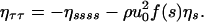
Physically, the meaning of this result is as follows: For a heavy flag in a rapid flow, the added mass effect due to fluid motion is negligible so that the primary effect of the fluid is an inertial pressure forcing on the plate. For a plate of length L weakly tilted at an angle θ, the excess fluid pressure on it scales as ρfU2θ, where ρf is the fluid density and U is the fluid velocity. The inertia of a plate of thickness h, of density ρs, and oscillating at a frequency ωa scales as ρshω2aLθ. Equating the two yields the frequency of oscillations of a freely hinged rigid plate approximately parallel to the flow ωa ∼ (ρfU2/ρshL)1/2. On the other hand, for a flexible plate of thickness h and made of a material of Young's modulus E (bending stiffness of order Eh3) the elastic restoring force per unit length due to a deflection by the same angle θ scales as Eh3θ/L3 so that the frequency of the lowest mode of free bending vibrations of a flexible plate ωb ∼ (Eh2/ρsL4)1/2. Equating the two yields a critical velocity for the onset of flutter of a plate of given length Uc ∼ (Eh3/ρfL3)1/2. As we will see in the following sections, this simple result arises naturally from the analysis of the governing equations of motion of the flag and the fluid. In particular, our analysis is capable of accounting for the unsteady nature of the problem in terms of the added mass of the fluid and the vortex shedding from the trailing edge in terms of the seminal ideas of Theodorsen (3).
Equations of Motion
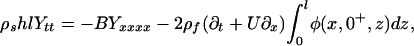
Elasticity. We consider the dynamics of an inextensible two-dimensional elastic plateb of length L, width l, and thickness h ≪ L ≪ l, made of a material of density ρs and Young's modulus E embedded in a three-dimensional parallel flow of an ambient fluid with a density ρf and kinematic viscosity ν, shown schematically in Fig. 1. We assume that the leading edge of the naturally straight plate is clamped at the origin with its tangent along the x axis and that there are no variations in the flow along the direction of the clamped edge, and that far from the plate, the fluid velocity U = Ux. Then the transverse position of the plate Y(x, t) satisfies the equation of motion (10):
 |
[1] |
Here, and elsewhere Ab ≡ ∂A/∂b, m = ρshl is the mass per unit length of the flag, B = Eh3l/12(1 – σ2) is its flexural rigidity (here σ is the Poisson ratio of the material), ΔP is the pressure difference across the plate due to fluid flow, and T is the tension in the flag induced by the flow.
Fig. 1.

Schematic representation of the system. An elastic plate of length L, width l, and thickness h ≪ l, L clamped at the origin is embedded in a three-dimensional parallel flow of an inviscid fluid with velocity U in the x direction. Its transverse position is denoted by Y (x, t). The incomplete cylinders depict the real vortex that is shed from the trailing edge, and an imaginary vortex in the interior of the plate that moves inwards, and is necessary to preserve the impenetrability of the boundary of the plate.
In deriving Eq. 1, we have assumed that the slope of the plate is small so that we can neglect the effect of any geometrical nonlinearities; these become important in determining the detailed evolution of the instability but are not relevant in understanding the onset of flutter. For the case when the leading edge of the flag is clamped and the trailing edge is free, the boundary conditions associated with Eq. 1 are (10):
 |
[2] |
To close the system of Eqs. 1 and 2, we must evaluate the fluid pressure ΔP by solving the equations of motion for the fluid in the presence of the moving plate.
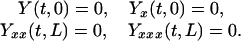
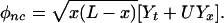
Aerodynamics. We will assume that the flow is incompressible, inviscid, and irrotational. Then the tension in the flag T = 0,c and we may describe the unsteady fluid flow as a superposition of a noncirculatory flow and a circulatory flow associated with vortex shedding, following the pioneering work of Theodorsen (3). This allows us to respect Kelvin's theorem preserving the total vorticity of the inviscid system (which is always zero) by considering a vortex sheet in the fluid and an image sheet of opposite strength that is in the plate. Both flows may be described by a disturbance velocity potential φ, which itself may be decomposed into a noncirculatory potential, φnc, and a circulatory potential, φγ, with φ = φnc + φγ. Then φ satisfies the Laplace equation, ∇2φ = 0, characterizing the two-dimensional fluid velocity field, (u, v) = (φx, φy), with boundary conditions on the flag, ∇φ·n|Y=0 = Yt + UYx, and in the far-field, ∇φ → 0 as r → ∞.
For small deflections of the plate, the transverse velocity of the fluid, v, varies slowly along the plate. Then we may use a classical result from airfoil theory (11) for an airfoil moving with a velocity v = Yt + UYx, assumed to be vary only slightly from a constant, to deduce an approximate form for the noncirculatory velocity potential along the plate as (12)
 |
[3] |
This expression neglects terms of order O(UYxt) (and higher) that correspond physically to the rate of change of the local angle of the plate, which can only be systematically accounted for in a non-local way.d A true check of the validity of our model requires a comparison with the solution of the complete problem, constituting work in progress. However, as we will see, this simple model is able to capture the qualitative essence of the mechanisms involved and agrees reasonably with experiments. Proceeding forward, then, we can use the linearized Bernoulli relation to determine the jump in pressure due to the noncirculatory flow so that
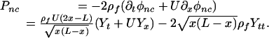 |
[4] |
Here we note that the fluid added-mass effecte is characterized by the term proportional to Ytt, and again we have neglected terms of order O(Yxt) and higher associated with very slow changes in the slope of the plate.
Kelvin's theorem demands that vorticity is conserved in an inviscid flow of given topology. Thus, the circulatory flow associated with vortex shedding from the trailing edge requires a vorticity distribution in the wake of the airfoil and a (bound) vorticity distribution in the airfoil to conserve the total vorticity. If a point vortex shed from the trailing edge of the plate with strength –Γ has a position (L/2)(1 + X0), X0 ≥ 1, we must add a point vortex of strength Γ in the interior of the sheet at (L/2)(1 + (1/X0)). This leads to a circulatory velocity potential along the plate (3–5)
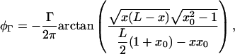 |
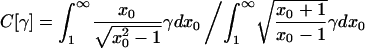
where x0 = ((x0 + 1/X0)/2) characterizes the nondimensional center of vorticity, which is at ((1 + x0)/2). Therefore, for a distribution of vortices of strength γ defined by Γ = γ(L/2)dx0, the circulatory velocity potential is
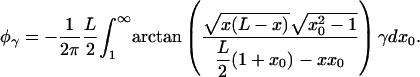 |
[5] |
To calculate the pressure difference due to the circulatory flow, we assume that the shed vorticity moves with the flow velocity U so that ∂tφγ = (2/L)U∂x0 φγ.f Then, we may write (3)
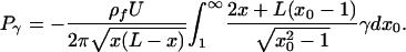 |
[6] |
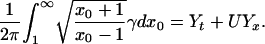
The vortex sheet strength γ in the previous expression is determined by using the Kutta condition, which enforces the physically reasonable condition that the horizontal component of the velocity does not diverge at the trailing edge:g
 |
[7] |
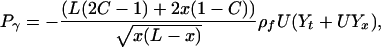
Substituting Eqs. 3 and 5 into Eq. 7 yields the relation
 |
[8] |
Multiplying and dividing Eq. 6 by the two sides of Eq. 8 we obtain
 |
[9] |
where
 |
[10] |
is the Theodorsen functional (3) quantifying the unsteadiness of the flow. For example, for an airfoil at rest that starts to move suddenly at velocity U, γ = δ(x0 – (2/L) Ut) corresponding to the generation of lift due to a vortex that is shed and advected with the fluid. Then
 |
[11] |
We see that as Ut/L → ∞, C → 1, which limit corresponds to the realization of the Kutta condition for steady flow (12). Adding up the contributions to the pressure jump across the plate from the circulatory and noncirculatory flows given by Eqs. 5 and 9 we have ΔP = Pnc + Pγ, i.e.,
 |
[12] |
where the dimensionless functions n(s) and f(s) are
 |
[13] |
 |
[14] |
By way of comparison, our consideration of the fluid forces embodied in Eq. 12 differs from that of Crighton and Oswell (13), who treated the case of an infinite plate avoiding many of the complications of a finite plate, and is also different from the treatment of Fitt and Pope (8), who neglected the role of fluid added-mass. In the slightly different context of fish swimming, Lighthill (14) considered an undulating slender body such as an eel swimming at high Reynolds number for which he wrote
 |
for the lateral force exerted by the fish on a water slice by equating it to the material derivative of the momentum liberated in the fluid, with a(x) as an ad hoc representation of the apparent mass of the cross section at x, and v = Yt + UYx. Our theory differs from this by explicitly accounting for the potential flow field and vortex shedding using the Theodorsen approach in the limit of small deformations when the vertical velocity v is almost constant, and suggests an obvious extension of our work to locomotion.
Aeroelasticity. Substituting Eq. 12 in Eq. 1 (with T = 0) gives us a single equation of motion for the hydrodynamically driven plate
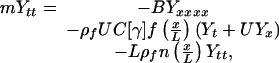 |
[15] |
with C[γ] determined by Eq. 10. We note that Eq. 15 accounts for the effects of unsteady flow past a flexible plate of finite length, including vortex shedding and fluid added-mass, but is only valid for small-amplitude motions. To make Eq. 15 dimensionless, we scale all lengths with the length L of the flag, so that x = sL, Y = ηL, and scale time with the bending time L/UB, where 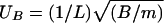 is the velocity of bending waves of wavelength 2π L. Then Eq. 15 may be written as
 |
[16] |
Here 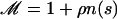 , where ρ = (lρfL/m) = (ρf/ρs)(L/h) characterizes the added mass effect and the parameter u0 = (U/Ub) is the ratio of the fluid velocity to the bending wave velocity in the plate. We can use symmetry arguments to justify the aerodynamic pressure C[γ] f(s)(ητ + u0ηs): the term ηs arises because the moving fluid breaks the s → –s symmetry, while the term ητ arises because the plate exchanges momentum with the fluid, so that the time reversibility τ → –τ symmetry is also broken. These two leading terms in the pressure, which could have been written down on grounds of symmetry, correspond to a lift force proportional to ηs and a frictional damping proportional to ητ. By considering the detailed physical mechanisms, we find that the actual form of these terms is more complicated due to the inhomogeneous dimensionless functions f(s), n(s). Thus, understanding the flapping instability reduces to a stability analysis of the trivial solution η = 0 of the system 16, 2 to perturbations as a function of the problem parameters ρ, u0.
Since the free vortex sheet is advected with the flow, the vorticity distribution may be written as γ = γ((2U/L) (t – t1) – x0) and t1 being the time at which shedding occurs, which in dimensionless terms reads γ = γ(2u0(τ – τ1) – x0). Accounting for the oscillatory nature of the flapping instability with an unknown frequency ω suggests that an equivalent description of the vorticity distribution is given by γ = Re(Aei(ω(τ–τ1)–qxo), where q = ω/2u0 is a nondimensional wave number of the vortex sheet. Using the above traveling wave form of the vorticity distribution in Eq. 10 we get an expression for the Theodorsen function (3),
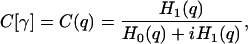 |
[17] |
where Hi are Hankel functions of ith order. The system 16, 17, 2 completes the formulation of the problem for the stability of a straight flag.
Stability Analysis
To understand the mechanism of instability of the trivial solution of 16, 2, we note that for a typical textile flag in fast-moving air, the added-mass parameter ρ ≤ 1, while the scaled velocity u0 ≫ 1. We can thus simplify Eq. 16 even further by looking at the asymptotic limit ρ → 0, u0 → ∞ but with the scaled aerodynamic pressure  being finite. Furthermore, in this limit the vorticity is advected rapidly from the trailing edge so that we can use the quasi-steady approximation (15). This supposes that the lift forces are slaved adiabatically to those on a stationary airfoil with the given instantaneous transverse velocity Yt + UYx, so that C → 1, following Eq. 11. By assuming that the Kutta condition is satisfied instantaneously, we overestimate the lift forces and thus expect to get a threshold for stability that is slightly lower than if C ≠ 1. Then Eq. 16 becomes time-reversible:h
 |
[18] |
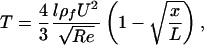
The two terms on the right-hand side of Eq. 18 correspond to the existence of two different modes of oscillation: (i) that of a flexible plate bending with a frequency that is dependent on the wavenumber and (ii) that of a rigid plate in the presence of flow-aligning aerodynamic forces. In this limiting case, we can clearly see the physical mechanisms at work in determining the stability or instability of the plate: Small plates are very stiff in bending, but as the plate length becomes large enough for the fluid pressure to excite a resonant bending instability, the plate starts to flutter. Equivalently, the instability is observed when the bending oscillation frequency become of the order of the frequency of oscillations of a hinged rigid plate immersed in a flow. This simple picture allows us to estimate the criterion for instability by balancing the bending forces (Eh3η/L4) with the aerodynamic forces ρfU2(η/L) so that for a given flow field the critical velocity of the fluid above which the flag will flutter scales as
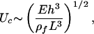 |
[19] |
which in dimensionless terms corresponds to u0 ∼ 1/ρ1/2. Then the typical flapping frequency ω is given by balancing plate inertia ρshω2η with the aerodynamic forces ρfU2(η/L) and leads to
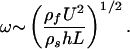 |
[20] |
To see this quantitatively, we look for solutions to 18, 2 of the form η(s, τ) = ξ(s)eστ and compute the associated spectrum, σ(u0) using auto (16). In Fig. 2, we show that for 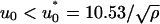 with ρ ≪ 1, the spectrum lies on the imaginary axis as expected, and as u0 ≥ u*0, the four eigenvalues with smallest absolute value collide and split, leading to an instability via a 1:1 resonance (17).
Fig. 2.

Spectrum Im(σ), Re(σ) of the system (18,2) when ρ ≪ 1 (with 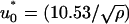 ). The eigenvalues with the smallest absolute value are plotted for u0 = 0.9u*0 (disks) and for u0 = 1.1u*0 (square). We see that instability occurs via a collision and splitting of two pairs of eigenvalues along the imaginary axis (indicated by the arrows) and is a signature of a 1:1 resonance mechanism in a time-reversible system.
As ρ ∼ O(1), the effective damping term, ρu0Cf(s)ητ, becomes important, so that the spectrum is shifted to the left, i.e., Re(σ) < 0. In this case, although the instability is not directly related to a resonance, the physical mechanism remains the same, i.e., a competition between the destabilizing influence of part of the fluid inertia and the stabilizing influence of elastic bending, subject to an effective damping due to fluid motion. Substituting the separable form η(s, τ) = ξ(s)eστ into Eq. 16 we get
 |
[21] |
At the onset of the oscillatory instability, Re(σ) = 0, so that σ = iω and C[γ] is given by Eq. 17. Together with the boundary conditions 2, this yields a nonlinear eigenvalue problem for ω, ξ since the Theodorsen function C(q) = C(ω/2u0) depends on ω. We again solve the resulting system numerically with the auto package (16), using a continuation scheme in ω starting with a guess for the Theodorsen function C(ω/2u0) = C(0) = 1. The results, shown in Fig. 3, show that when u0 > u*0(ρ), Re(σ) > 0 with Im(σ) ≠ 0, i.e., an oscillatory instability leading to flutter arises. We see that for sufficiently large u0, the plate is always unstable, i.e., large enough fluid velocities will always destabilize the elastic plate. As ρ ≫ 1, the added mass effect becomes relatively more important and it is easier for the higher modes of the plate to be excited. We note that the stability boundary when C ≠ 1 accounting for vortex shedding corresponds to a higher value of the scaled fluid velocity u0 than that obtained by using the quasi-steady approximation C = 1, and is a consequence of the quasi-steady approximation, which overestimates the lift forces. In Fig. 3 Inset, we see that as ρ → 0, q → 0. Therefore, C(q) = C(0) = 1 so that in this limit the quasi-steady hypothesis is a good approximation. In Fig. 4 we show the mode shapes when ρ < 1 and ρ ≫ 1; as expected, the most unstable mode for ρ ≫ 1 is not the fundamental mode of the plate. We also see that the normalized amplitude of the unstable modes is maximal at the trailing edge; this is a consequence of the inhomogeneous functions f(s), n(s) in Eq. 16 as well as the clamped leading edge and a free trailing edge.
Fig. 3.

Stability diagram obtained by solving the eigenvalue problem 16, 2 parametrized in terms of the scaled added mass, ρ, and the scaled flow velocity, u0. The thin dashed line represents the transition curve using the quasi-steady approximation where C = 1; for values of ρ, u0 below this line, the flag is stable, and for values above it, it is unstable. The thin solid line represents the transition curve when vortex shedding is taken into account, i.e., C ≠ 1. The role of the third dimension and flag tension is considered in the appendices and changes the marginal stability curve slightly. The bold solid line is obtained by including three-dimensional effects using a simple model (see Appendix 1) for a flag of aspect ratio r = 2.5, and the bold dashed solid line takes into account the tension in the flag that arises due to viscous effects via a simple estimate of the Blasius boundary layer (see Appendix 2) with Re = 104. The dots correspond to experimental data characterizing the transition to flutter in three-dimensional flows past flexible sheets of paper (7); the large error bars are a consequence of the variations due to three-dimensional effects as well as regions of bistability where both the flapping and stationary state are stable. (Inset) The dimensionless wavenumber of the instability q = (ω/2u0) as a function of ρ. When ρ ≪ 1, q tends to be zero and C(q) → 1.
Fig. 4.

Snapshots corresponding to the mode of instability ξ(s) with ρ = 0.2, u0 ≈ 66 (a) and ρ = 25, u0 ≈ 6.6 (b). We see that for sufficiently large values of the added mass parameter ρ, the primary instability of the flag flutter occurs in a higher mode than otherwise.
In Fig. 2 we also show the experimental transition curve obtained from a recent study on the onset of flutter in paper sheets (7). The large error bars in the experimental data are due to the fact that there is a region of bistability wherein both the straight and the flapping sheet are stable. Nevertheless, we see that we do capture the qualitative trends of the experiments, and in the following discussion we show that it is possible to do slightly better quantitatively by accounting for the effects of the tension in the flag due to viscous boundary layers and the third dimension.
Discussion
Our linearized theory cannot capture the bistability in the transition to flutter without accounting for the various possible nonlinearities in the system arising from geometry. But even without accounting for these nonlinearities, there is a systematic discrepancy between our theory and the data, which consistently show a higher value of u0 for the onset of the instability. While there are a number of possible reasons for this, we believe that there are three likely candidates: The role of nonlocal interactions, three-dimensional effects, and the tension in the plate induced by the Blasius boundary layer, all of which would tend to stabilize the sheet and thus push the onset to higher values of u0. Postponing the question of nonlocal interactions to the future, in Appendix 1 we describe a simple model to account for three-dimensional effects and show that it pushes up the stability boundary as shown in Fig. 2. An explanation of this effect follows immediately from the fact that the added-mass parameter is rescaled due to the effects of the lateral boundaries of the flag. In Appendix 2, we consider the role of the tension in the flag due to the fluid induced shear at large but finite Reynolds numbers. Using the Blasius boundary layer calculation to determine the tension, T, via (I.1) a reworking of the stability analysis in the previous section pushes up the marginal stability curve by ≈20% when Re ∼ 104, making the comparison with the experimental data quantitatively better. A final remark concerns the role of the free vortex sheet behind the flag. We have assumed that this sheet is localized to the vicinity of y = 0, but experimental observations (6, 7) show that a Kelvin–Helmholtz-like instability destabilizes the sheet giving it a transverse velocity component. Thus, the vortex sheet is advected at a velocity slower than that of the fluid. Neglecting the transverse dynamics of the vortex sheet as done here overestimates the lift forces and lowers the marginal stability curve for the onset of the instability.
The commonplace occurrence of flutter in a flag belies the complexity hidden in this phenomenon. Extracting a qualitative and quantitative understanding involves the consideration of a number of effects. Our hierarchy of models starting with a relatively simple physical picture of the basic resonance-like behavior to the more sophisticated analyses in the quasi-steady and the unsteady cases have allowed us to dissect the physical mechanisms involved. In particular, we account for the finite length and finite bending stiffness of the sheet, as well as the fluid effects due to added-mass, vortex shedding, three-dimensional flow, and viscous boundary layer drag. We also provide a relatively simple criteria for the onset of the instability in terms of the scaling laws (19, 20). There are clear avenues for further questions, the most prominent of which include a detailed comparison with a two-dimensional numerical simulation and further experiments; these will be reported elsewhere.
Acknowledgments
This work was begun and brought to fruition when we were at Cambridge University; we dedicate this paper to the memory of Professor David G. Crighton, who first interested one of us (L.M.) in this problem nearly a decade ago. We thank M. Shelley, N. Vandenburghe, and J. Zhang for sharing their preprint with us. This work was supported by the European Community through Marie-Curie Fellowship HPMF-2002-01915 (to M.A.) and the U.S. Office of Naval Research through a Young Investigator Award (to L.M.).
Appendix 1: Three-Dimensional Effects
In this appendix, we introduce an approach that accounts for three-dimensional effects. By introducing the noncirculatory velocity potential (Eq. 3), the flag is assumed to a flag of infinite span moving in the y direction with a velocity v. As a consequence, φnc did not depend on the z variable. To generalize the analysis of Theodorsen to the case when the flag has finite width, we assume the flag to be a rectangular plate of length L and width l. Integrating the equation of motion for the plate (Eq. 1) in the z direction to simplify the problem in this case yields
 |
[22] |
where we have used the linearized Bernoulli equation to determine the pressure. The last term in Eq. 22 simplifies when the flag is infinitely wide, i.e., when φ(x, 0+, z) = φ(x, 0+). More generally, we define the function A(r)
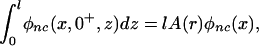 |
[23] |
where r = (l/L) is the aspect ratio of the flag, and φnc(x, 0+) is the noncirculatory potential corresponding to the infinitely wide flag. A(r) characterizes the importance of the third dimension, and we expect that A(r)/r → 1 when r → 0 and A(r) → 1 when r → ∞. Indeed, using a commercially available software program femlab, to compute φnc at y = 0+ as a function of r confirms this, as shown in Fig. 5. Similarly, since the circulatory potential computed via the Kutta condition (Eq. 8) is also proportional to A(r) so that Eq. 22 reads
 |
[24] |
We see that including three dimensional effects modify the added mass parameter and the pressure, both of which are rescaled by a factor A(r), which is smaller than unity. As a consequence, the marginal stability curve shown in Fig. 3 is shifted up, as shown in Fig. 3, and is even closer to the experimental data. Of course, this simple model ignores the additional complexity of vorticity distributions along the edges of the flag, at z = 0,l, and is thus only suggestive of the general trend.
Fig. 5.

Three-dimensional effects. (a) Plot of the noncirculatory velocity potential for an aspect ratio of the flag r = l/L = 1.5. (b) Plot of the aspect ratio function A(r) as function of r.
Appendix 2: Tension Induced by the Boundary Layer
In high Reynolds number flows past the flag, the viscous boundary layer exerts a shear stress on the flag that puts in under a variable tension T which stretches the flag nonuniformly, being largest at the clamped anchor and vanishing at the trailing edge. This stabilizes the flag to some extent; in particular, it may be responsible for the experimentally observed subcritical nature of the instability (6). Restricting ourselves here to the case of the linearized theory for a slightly deformed flag with a Blasius boundary layer leads to a wall shear stress 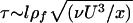 (12), where ν is the kinematic viscosity of the fluid. When combined with the equation for the balance of horizontal forces Tx = –τ and the boundary condition T(L) = 0, we find that
 |
[25] |
where the characteristic Reynolds number is defined as Re = UL/ν ≫ 1. Using this simple relation in Eq. 1 yields an eigenvalue problem similar to 21 for the instability threshold. Solving this with Re ∼ 104 shifts the marginal stability curve upwards in the direction of the experimentally obtained one, as shown in Fig. 3, but the effect is small.
Footnotes
Our analysis also carries over to the case of an elastic filament in a two-dimensional parallel flow.
In the appendices, we treat the case where T ≠ 0 due to the presence of a Blasius boundary layer.
The general solution of the Laplace equation in two dimensions with the given boundary conditions may be written as φ = ∫ dx′L(Yt + UYx)/|x – x′| and yields a nonlocal potential. However, when the transverse velocity Yt + UYx varies slowly in space and is close to a constant, we may use the local approximation given by Eq. 3.
When the plate moves, fluid must also be displaced and the sheet behaves as if it had more inertia (12).
This implies a neglect of any acceleration phase of the vorticity, a reasonable assumption at high Re.
This is tantamount to the statement that that the inclusion of viscosity, no matter how small, will regularize the flow in the vicinity of the trailing edge.
This is because the term breaking time reversal symmetry ρu0ητ becomes negligibly small.
References
- 1.Païdoussis, M. P. (1998) Fluid-Structure Interaction: Slender and Axial Flow (Academic, London).
- 2.Lord Rayleigh (1879) Proc. Lond. Math. Soc. X, 4–13. [Google Scholar]
- 3.Theodorsen, T. (1935) NACA Report 496, http://naca.larc.nasa.gov/reports/1935/naca-report-496.
- 4.von Karman, T. & Burger, J. M. (1935) in Aerodynamic Theory, ed. Durand, W. F. (Springer, Berlin), vol. 2.
- 5.Glauert, H. (1997) Elements of Aerofoil and Airscrew Theory (Cambridge Univ. Press, Cambridge, U.K.), 2nd Ed.
- 6.Zhang, J., Childress, S., Libchaber, A. & Shelley, M. (2000) Nature 408, 835. [DOI] [PubMed] [Google Scholar]
- 7.Watanabe, Y., Suzuki, S., Sugihara, M. & Sueoka, Y. (2002) J. Fluids Struct. 16, 529. [Google Scholar]
- 8.Fitt, A. D. & Pope, M. P. (2001) J. Eng. Math 40, 227. [Google Scholar]
- 9.Zhu, L. & Peskin, C. S. (2002) J. Comp. Phys. 179, 452. [Google Scholar]
- 10.Landau, L. D. & Lifshitz, E. M. (1987) Theory of Elasticity (Pergamon, New York).
- 11.Milne-Thompson, L. M. (1960) Theoretical Hydrodynamics (Macmillan, New York).
- 12.Landau, L. D. & Lifshitz, E. M. (1987) Fluid Mechanics (Pergamon, New York).
- 13.Crighton, D. G. & Oswell, J. (1991) Philos. Trans. R. Soc. London A 335, 557. [Google Scholar]
- 14.Lighthill, J. (1975) Mathematical Biofluiddynamics (Soc. Indust. Appl. Math., Philadelphia).
- 15.Fung, Y. C. (1969) An Introduction to the Theory of Aeroelasticity (Dover Phoenix Editions, Mineola, NY).
- 16.Doedel, E. J. (2001) auto 2000, http://sourceforge.net/projects/auto2000.
- 17.Marsden, J. E. & Ratiu, T. S. (1994) Introduction to Mechanics and Symmetry (Springer, New York).