Abstract
3D printing has been used to create complex arterial phantoms to advance device testing and physiological condition evaluation. Stereolithographic (STL) files of patient-specific cardiovascular anatomy are acquired to build cardiac vasculature through advanced mesh-manipulation techniques. Management of distal branches in the arterial tree is important to make such phantoms practicable.
We investigated methods to manage the distal arterial flow resistance and pressure thus creating physiologically and geometrically accurate phantoms that can be used for simulations of image-guided interventional procedures with new devices. Patient specific CT data were imported into a Vital Imaging workstation, segmented, and exported as STL files. Using a mesh-manipulation program (Meshmixer) we created flow models of the coronary tree. Distal arteries were connected to a compliance chamber. The phantom was then printed using a Stratasys Connex3 multimaterial printer: the vessel in TangoPlus and the fluid flow simulation chamber in Vero. The model was connected to a programmable pump and pressure sensors measured flow characteristics through the phantoms. Physiological flow simulations for patient-specific vasculature were done for six cardiac models (three different vasculatures comparing two new designs). For the coronary phantom we obtained physiologically relevant waves which oscillated between 80 and 120 mmHg and a flow rate of ~125 ml/min, within the literature reported values. The pressure wave was similar with those acquired in human patients. Thus we demonstrated that 3D printed phantoms can be used not only to reproduce the correct patient anatomy for device testing in image-guided interventions, but also for physiological simulations. This has great potential to advance treatment assessment and diagnosis.
Introduction
3D printing of patient specific vascular phantoms has provided the medical community with a new set of tools for device testing1 and endovascular treatment planning.2 Until recently vascular phantoms3–8 were a simplification of the patient anatomy. They modeled one main artery, rarely included branching arteries and the arterial wall mechanical properties were ignored. Geometry extension and inclusion of pathologies such as atherosclerotic plaques or surrounding anatomical structures was practically nonexistent. These simple patient specific geometries were used to evaluate new devices9, 10 or well established ones.11 While such approaches are needed to report device behavior in a simple reproducible setup, they lack the true clinical situations test, such as device navigation in complex vascular systems, modeling of challenging pathologies, or mimicking of physiological aspects of the blood flow.
As vascular phantoms become more complex, distal flow management, especially in the cases with many distal branching such as cardiac, becomes challenging. One way to handle this situation is to use the approaches such as those developed by Russ et. al.13 and O’Hara et. al.14 To manage the distal flow they merged the smaller vessels into one to four outlets. One of the limitations of the design is that the arterial pressure becomes physiologically inaccurate. The method causes an increase in hydraulic resistance and therefore an increase in pressure in the proximal part of the phantom which is not only physiologically inaccurate but it can also change the actual vessel diameter as well as damage the phantom. Therefore, a simple merging technique without accounting for flow optimization is not physiologically accurate.
The purpose of this project is to study and optimize the outflow design of the 3D printed patient-specific vascular phantoms to reproduce realistic blood flow conditions. Using 3D mesh manipulations and CAD designs we investigated three approaches for many distal branches. The first method uses the merging technique developed previously13, 14 which creates a practical model with strict limitations on the outflow characteristics. The second approach uses a collection reservoir that allows for the vessel branches to remain separate. This approach is more customizable allowing global outflow adjustments. Using the second approach we were able to control both, flow rates and pressure waves within physiologically relevant values. The third approach uses different collection reservoirs where arteries supplying blood to specific regions are separated. This approach is highly customizable and allows for selective distal resistance adjustments.
This study focuses on recreating flow through the heart coronary arteries. All three designs were applied to coronary trees in three patients. The main three branches: Left Anterior Descending (LAD), Circumflex (LCX), and Right Coronary Artery (RCA) as well as daughter vessel branches were included in the design and the three approaches were employed. In addition to the outflow design we investigated the effect of the 3D printed materials on the vessel compliancy and used this information to design coronary trees with known wall mechanical properties.
Materials and Methods
Collection and analyses of all scan and patient data has been performed within the scope of a research protocol approved by the University at Buffalo Institutional Review Board (IRB).
Image Segmentation
CT Coronary Angiography scans were acquired using a CT scanner Aquilion One (Toshiba Medical Systems, Otawara, Japan). Scan data is acquired with 0.429mm pixel size and 0.5mm slice thickness. 3D data volumes were uploaded into a Vitrea 3D workstation (Vital Images, Inc. Minnetonka MN) where they were 3D rendered and processed (Figure 1, left). The coronary tree was segmented using the Vital Imaging coronary segmentation capabilities, which automatically isolates the main coronary arteries: Left Anterior Descending (LAD), Circumflex (LCX), and Right Coronary Artery (RCA). To include the secondary branches an interactive vessel select/growth tool is used. To verify the accuracy of the automatic segmentation, the segmentation was visualized in both 3D render curved MPR views (Figure 1, right) and manually edited the centerlines and the segmentation profiles if needed. Any discrepancies were manually corrected on a slice-by-slice basis with centerline and vessel profile editing tools. Finally, the segmented volumes were exported as STL files for use in later steps.
Figure 1.
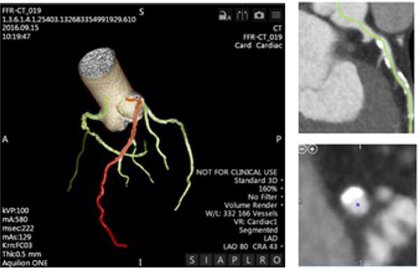
3D data volumes uploaded to Vital Images and the coronary vasculature is segmented out. Vessel centerline manually segmented to avoid vessel stenosis.
Though the STL model is rendered through Vitrea, further simplification and sculpting of the vasculature is needed for the file to be 3D printable. We then imported the STL model into a surface mesh manipulation program (Meshmixer). First small fragments disconnected and surrounding the vessel were removed. The mesh was then analyzed through the program’s inspector for problematic contours and holes in the mesh. We then removed small, unwanted branches and smoothed the mesh if needed. Once the geometry of the mesh was cleaned and free of errors, the inlets and the outlets of the vessel were perpendicularly cut. Next step was outflow design which was done using the three approaches previously described: merging, common compliance outflow chamber and targeted compliance outflow chamber.
Merging Approach
The merging approach was explained in detail by O’Hara et. al.14 and it will be only briefly outlined here. An STL file is imported into Meshmixer, groups of vessel branches are merged distally into one outflow using the “add tube” function in Meshmixer. This function allows for two or more vessel branches to be joined into a single outflow tube by inserting connecting spline curves between the branch terminals and a desired outflow, Figure 2. The branching groups are selected based on the anatomical location, e.g. left side coronary tree. The radius dimensions and degree of curvature throughout the outflow tube can be chosen by the user. The widths of each vessel can be changed to create a specific resistance resulting in a controlled fluid flow. If outflow design is inaccurate, this approach could be physiologically inaccurate because when the vessels are merged, an increased hydraulic resistance occurs in response to the outflow diameter and added tortuosity. To properly design the outflow the “Cube Law” which states that as the diameter decreases, the flow rate also decreases: , must be accounted for. To accommodate for this we have modified the merging technique compared to previous reports. As the distal branches merge onto the outflow collector we increase diameter to accommodate for the extra flow. The diameter was determined such that the cross sectional area was equal to the sum of the merged vessels.
Figure 2.
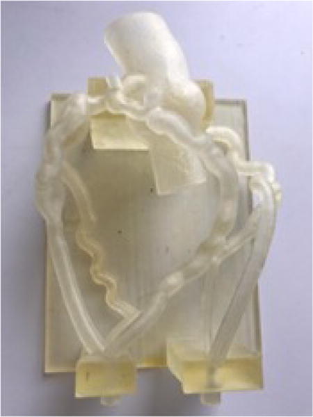
Merged Approach 3D printed as a single material
Common Outflow Compliance Chamber Approach
For this approach we decided to design a phantom where we avoided the complications created by the merging process described above. One way to do this is to collect all the branches in one sealed chamber. Since both sides of the coronary flow would be collected in one chamber, both would be subject to the identical pressures. In certain situations this might result in no flow or even reverse flow in one side of the phantom. Hence each side needs to be treated separately.
Once we imported the file in Meshmixer we isolated only one coronary tree, Figure 3. We then inserted a plane as a new object and placed it below the vessel outlets. The “add tube” meshmixer functionality was used to create a spline tube between the vessel end and the plane. The tubing was carefully placed so that it formed a continuation of the vessel curvature as well as staying within the bounds of the flow collection chamber. A plane cut was next administered so that half of the additional tubing was included in the vessel model. This plane cut assured that each outlet would pass perpendicularly through the fluid collection chamber. For data collection purposes, access ports were placed proximal and distal to the stenosed region, acting as sites to place fluid pressor sensors. The Meshmixer “make solid” functionality was employed to create an offset surface of 1.5mm, which would be combined with the vessel lumen to act as the vessel wall. Plane cuts were made at the inlet and the tips of each outlet and a hollowed out coronary artery resulted. (Figure 3)
Figure 3.
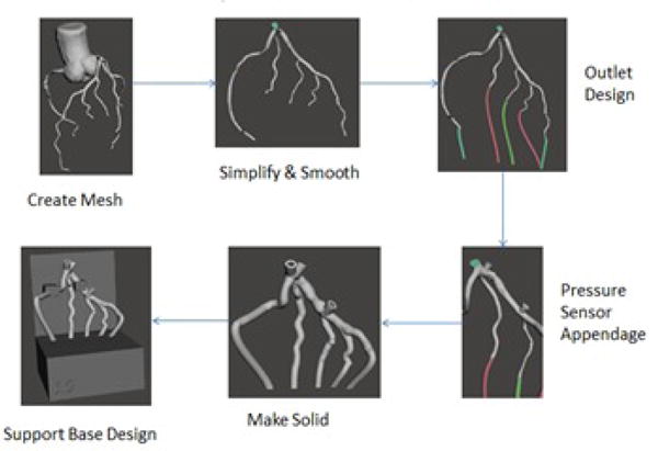
Flow diagram showing the steps used in the Common Outflow Compliance Approach from the time the STL is imported into Meshmixer to the completion of the segmentation process.
Figure 4 outlines a typical flow diagram going into further detail to append a pre-designed custom flow simulation chamber (base) STL to the solidified vasculature. The base is designed in Solid Works and an STL is appended to the Meshmixer vessel model. We can then transform the vessels so that each of the outlets are passing through the flow chamber and vessel branches are touching the wall of the base. Once the vessel and base objects are aligned, place cube on base object in appropriate position to support vessels, and combine cube with base. Subtract vessels from base using the Boolean Difference Operation to ensure no regions of overlap (a requirement for multi-material 3D Printing).
Figure 4.

Flow diagram showing steps performed to customize flow simulation chamber for patient-specific vessels. (a)Customizable flow chamber is inserted and (b) a vessel support mesh is appended to the base. (c) The Boolean Difference Operation ensures no region of overlap and (d) the vessel and base are fit together.
Targeted Outflow Compliance Approach
This third approach best resembles the human coronary anatomy and optimizes the distal pressure measurements as well as regional flow rate measurements. Figure 5 outlines the steps taken to create 3D model using the Targeted Outflow Compliance Approach.
Figure 5.
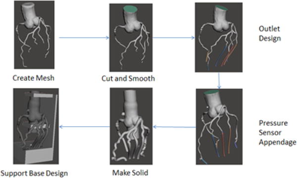
Flow diagram showing steps performed from the time the STL is imported into Meshmixer to 3D model ready to be printed using the Targeted Outflow Compliance Approach.
The major change in this design is the inclusion of the aortic root and associated coronary ostia/vessel attachments at the level of the coronary cusps. This is a very important aspect since the aorta acts as a compliance chamber regulating the amount of blood flowing through the coronary arteries. Though this design includes more anatomy, the vessel mesh is then manipulated in a similar manner as to the second approach. The most significant design change involves the location and placement of pressure sensor access ports (previously located proximal and distal to the stenosed region). Instead of placing the proximal access port just before the stenosed region, the port is built at the level of the aortic root itself. The vessel lumen is then solidified with the same procedure as the second approach.
A CAD designed base reservoir with three separate compartments is designed in Solid Works, and an STL model is appended to the vessel Meshmixer scene (in a similar manner as before) shown in Figure 6. The vessel is then transformed so that each of the outlets are passing into the correct compartments of the reservoir: all RCA branches pass through one compartment, all LCX branches pass through the second compartment, and all the LAD branches pass through the last compartment, Figure 6. The creation of three individual reservoir compartments allows for targeted distal resistance manipulation, which could simulate separate capillary beds for each main artery supply region. The Boolean Difference is used to ensure no regions of overlap between vessel and base (Figure 6). The chambers are sealed using a custom 3D printed seal and a door which contains one outlet for each chamber.
Figure 6.

Diagram showing the addition of the aorta with extending coronary arteries and the base reservoir after performance of the Boolean Difference Operation ready to be 3D printed.
3D Printing and Post-processing
With the design-stage complete, ready-to-print STL’s of the coronary arteries and the chamber are exported from Autodesk Meshmixer. It is important to note at this stage that approach one, the Merged Approach, can only be printed using a single material. We used TangoPlus to print these models on Objet PolyJet 3D printer, Model260 V (Objet-Stratasys, Inc. Eden Prairie, MN). The Common Outflow Compliance Approach and the Targeted Outflow Compliance Approach are printed on a multi-material printer. They are each exported individually and printed using Objet PolyJet 3D printer, Connex 3 multi-material (Objet-Stratasys, Inc. Eden Prairie, MN). The vessel and the flow simulation chamber are added to the printer tray and assembled together. The vessel is printed in TangoPlus and the fluid flow simulation chamber in VeroWhite. The TangoPlus is a soft, elastic and semitransparent material and the Vero is a hard, sturdy material that is a good support.
Printer support material is cleaned from the models using standard methods. Large portions of support are removed by hand from the outer regions of the model. A modified power washer is used to finely clean the model surface. Support is removed from the vessel inner lumen via manual cleaning with expired endovascular catheters and guidewires.
Due to inherent limitations of PolyJet 3D printing – namely, the presence of a support mixing layer – mechanical failures tend to occur at the interfaces between soft (Tango) and rigid (Vero) materials. To minimize the significance of this effect, we specify a separate STL shell at vessel and base object interface regions. This shell is printed out of the Tango and Vero Digital blend FLX9760-DM, allowing for much tighter adhesion of the vessel outlets and fluid collection chamber. To perform this operation in MeshMixer, we separated the triangular vertices of the base surrounding the vessel outlets from the rest of the base. The reinforcement mesh was bridged to create a solid object and the base was also bridged to once again create a solid object. The two meshes were then fit together perfectly as they were before; however, two different materials were able to be used to print out the base. Figure 7 visually depicts this process.
Figure 7.
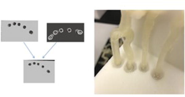
The reinforcements and the base are combined to create a sturdy base for the coronary arteries that allows for easy cleaning without subjecting the model to mesh tearing ease.
Compliance Determination
Current multi-material 3D printing offers a variety of soft material combinations which have various tensile strengths and elongations at break. A list of the multi-materials available with a Connex 3 –Stratasys is shown in Table 1. Access to such a variety of soft material should allow us to design vascular phantoms with a specific compliance which could simulate healthy vessels as well as rigid ones. To investigate this possibility we printed 50 mm long with a 3 mm inner diameter and 0.5 mm thickness. Vessels were connected via 7 French introducers to a manual water pump and a National Instruments pressure sensor. Air bubbles were removed and pressure was tracked by a Lab VIEW Data Acquisition Virtual Instrument. The experimental design is set up in Figure 8. Change in diameter was recorded as pressure was increased in increments of 30mmHg. Each vessel was measured along its major and minor axes. The compliance was measured according to the following formula:
| Equation 1 |
Table 1.
Elongation at break percentage correlated to tensile strength of digital materials
| FLX | FLX | FLX | FLX | FLX | FLX | RGD | RGD | RGD | ||
|---|---|---|---|---|---|---|---|---|---|---|
| Name | TANGO+ | 9740 | 9750 | 9760 | 9770 | 9785 | 9795 | 8630 | 8430 | 8425 |
| Tensile Strength (MPa) | 0.8–1.5 | 1.3–1.8 | 1.9–3.0 | 2.5–4.0 | 3.5–5.0 | 5.0–7.0 | 8.5–10.0 | 29–38 | 29–38 | 35–45 |
| Elongation at Break (%) | 170–220 | 110–130 | 95–110 | 75–85 | 65–80 | 55–65 | 35–45 | 25–35 | 25–35 | 20–30 |
Figure 8.
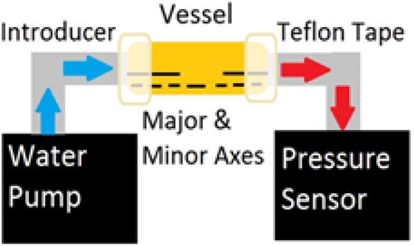
Compliance Experimental Design
Where; As was Cross-sectional area of systolic lumen, Ad was Cross-sectional area of diastolic lumen, Ps was Systolic pressure and Pd was Diastolic pressure. For our measurements the Pd set at 80 mmHg and Ps was set at 120 mmHg.
Phantom Flow Testing
The reservoir was sealed using a custom printed door, the chamber serves also as a compliance chamber which dumps the pressure wave similarly to a capillary bed. For the second approach, the reservoir door contains a single outflow tube. The third approach consists of a reservoir door with an outflow tube for each coronary artery and its correlated branches. The models were connected to a programmable pulsatile pump and the pressure drop across various features, such as stenosis was measured using pressure transducers. A flow sensor was used to ensure that the flow rate stayed at a constant 125 ml/min. A LabVIEW program recorded the pressure readings with respect to time by connecting the pressure sensor outlets to a Data Acquisition Board.
Results
Three separate patients’ cardiac vasculatures were obtained through CT scanning, 3D rendering and then 3D printing each with the three different approaches: the Merged Approach, the Common Outflow Compliance Approach, and the Targeted Outflow Compliance Approach. Figure 9 captures the optimal CT slice imported into Vital Images. Left Anterior Descending (LAD), Circumflex (LCX), and Right Coronary Artery (RCA) multi-planar reconstructions (MPRs) are also displayed in Figure 9 showing the centerline editing process undergone to maintain proper vasculature. Calcified lesions and moderate stenosis were observed in each of the three cases (see Table 2). Clinically, moderate stenosis = 40% to 70%, and severe = greater than 70%.
Figure 9.
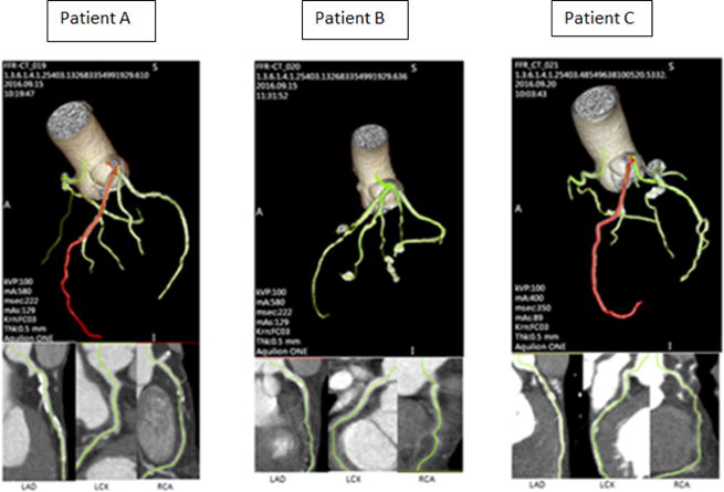
Three examples of coronary arteries captured in Vital Images as well as Multi-Planar Reconstructions (MPR’s) to edit centerlines of vessels.
Table 2.
Percent Stenosis of Main Coronary Arteries Determined by Vessel Diameter
| Patient | RCA Stenosis | LAD Stenosis | LCX Stenosis |
|---|---|---|---|
| Case A | 55% | 46% | 17% |
| Case B | N/A | 52% | 16% |
| Case C | N/A | 56% | N/A |
Figure 10 then displays the completed products of Patient A, B, and C created in Meshmixer using each of the three design approaches.
Figure 10.
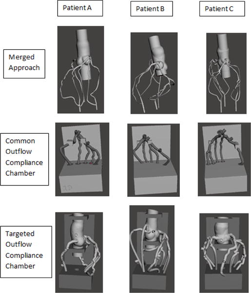
Meshmixer comparison of three different model design approaches for patient A, B, and C.
Each of the geometries were imported into Meshmixer and the phantoms were designed as described in the Methods sections. Figure 11 displays the three specific patient coronary anatomies 3D printed using the Common Outflow Compliance Approach and the Targeted Outflow Compliance approach. The two different bases, showing the difference between the single compartment base and the tricompartmental base simulating joint versus individual capillary beds are also shown in Figure 11. The design time varies between 30 minutes and 2 hours depending on the CT artifacts affecting the STL mesh quality with the common outflow compliance approach requiring half the design time.
Figure 11.
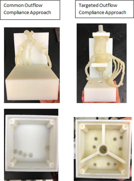
Simplified and Complex Coronary Models 3D printed and compared both frontal view and bottom view
3D printed phantoms of Case A are shown in Figure 11. A sample of the merged design is shown in Figure 2 and it was discussed in detail in previous publications.12–14 Overall snapshots and images of the compliance chambers are shown on the top row and the bottom row respectively. For flow establishment the chambers are sealed using a set a screws and a rubber 3D printed seal.
The average times required to 3D print the models is shown in Table 3. The common outflow phantom is the most economically viable, but as described above it comes at the cost of oversimplifying the system.
Table 3.
Printing time and material usage
| Model Type | Print time | Material Usage | Post Process Time |
|---|---|---|---|
| Merged outlets | 6 hours | 200g TangoPlus | 4–6 hours |
| Common Outflow Compliance | 8 hours | 294 g Vero, 36g TangoPlus | 1 hour |
| Targeted Outflow Compliance | 12 hours | 551 g Vero, 127 g TangoPlus | 4–6 hours |
For post processing, the phantoms were soaked in sodium hydroxide solution and the inner lumen was coated to reduce the roughness of the inner vessel lumen. Connectors were glued onto the inlet to allow fast interface with a flow loop and luer connectors were attached for pressure sensors embedment.
Each phantom was connected to a programmable pump and flow parameters were measured using flow and pressure sensors. The outflow was controlled using valves and the pump settings. The target flow was 250 ml/min in the full coronary tree if the model contained the entire tree or 125 ml/min if only one side was contained. Typical pressure waves are shown in Figure 13. The merged outflow was the most difficult to control and wide pressure variations were observed. We also encountered difficulties in maintaining the pressure limits within the physiological limits. The chamber based outflow was easily controlled, with the chambers acting as flow capacitors which provided wave dumping as encountered in the real cases.
Figure 13.

Pressure waves measured at the aorta (P1) and outlet (P2) for the merged model and Common outflow compliance where P1 is the proximal pressure and P2 is the distal pressure.
A typical compliance measuremen is shown in Figure 12. The plot shows a wide range of values, however for coronary applications we are interested mostly in the values below 150 mmHg. Using this type of plot we investigated 11 ruber-like materials and we estimated the compliance using Equation 1. (Figure 14)
Figure 12.
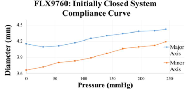
Compliance curve of FLX9760poly-blend material. An increase in pressure caused the diameter of both the minor and the major axes of the vessel to expand.
Figure 14.
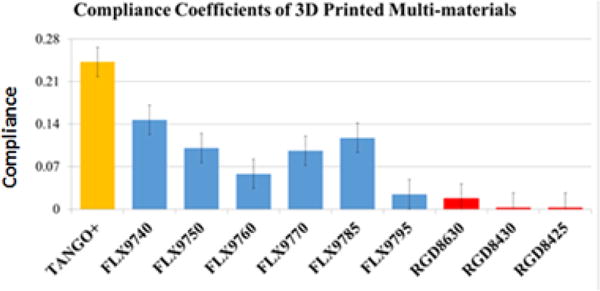
Multi-material compliance comparison
The compliance coefficient comparison among all of the different vessel multi-materials (with TangoPlus having the highest compliance) shows that compliance decreases with a decrease of the amount of TangoPlus in the multi-material. There was an average standard deviation in compliance between trials of 0.028. The compliance of a healthy adult must be >0.25 therefore all multi-materials tested are considered among the at risk population. Therefore, coronary artery compliance of both healthy and at risk populations can be closely modeled by 3D printed multi-material vascular models.
Discussion
We are presenting methods to create 3D printed flow simulation cardiac models using Stratasys Connex3 multi-material printers. These phantoms are patient-specific models that are used to recreate cardiac blood flow in healthy and diseased vessels as well as younger or older populations. These models have individual outflow tubes for each branch of the coronary arteries allowing for the fluid pressure to be adjusted until physiological relevant conditions are obtained.
Two new design approaches have been engineered: one with a 1-chambered outflow reservoir and the other with a 3-chambered outflow reservoir as well an inclusion of the aorta. Though the Common Outflow Compliance Approach is less accurate physiologically, it allows for a single branch to be targeted. The positive fact about this model is that is more simple and less likely to produce inaccurate results and it can be manufactured fairly easy and fast.
The 3-chambered outflow reservoir simulates the three separate capillary beds connected to each coronary artery creating an even more accurate fluid pressure through the coronary model. The incorporation of the aorta in the targeted model acts as a compliance chamber that controls both the blood flow and the pressure through the coronary arteries. The Target Outflow Compliance Approach is more physiologically accurate because it simulates each coronary artery flowing to its individual capillary bed.
For this model we accounted for the fact that each main coronary artery flows into a different capillary bed to supply different parts of the heart. Thus the pressure gradient and flow in each artery could be different.
One promising application we foresee for this model is CT-FFR software validations. With this new design we are able to separately control each coronary artery’s distal pressure and flow rate independently from the two other main coronary arteries. In addition we could use such a model to simulate the CT coronary angiography acquisitions to verify the accuracy of the segmentation algorithms and their impact on other diagnostic software.
Finally, this work introduced a method whereby digital materials are used to obtain not only geometrically accurate patient specific phantoms, but also allows for modeling of a range of vessel wall elasticities thus representing various disease states and patient-age variation. Further work will consider specific material combinations to represent specific age or disease states.
Conclusions
We are presenting a straightforward workflow for data acquisition, processing, and creation of physiologically and geometrically accurate phantoms to better model the distal arterial flow resistance and pressure of the coronary vasculature. For the coronary phantom our data was reported within the literature reported values with waves oscillating between 80 and 120mmHg and a flow rate of approximately 125ml/min. This shows that 3D printed phantoms can not only be used to reproduce the correct patient anatomy for image-guided endovascular device testing but that they can also be used for physiological simulations.
Acknowledgments
We would like to thank Liza Pope, Nicole Griffin, and Mariah Costa for their support in the completion of this project. This work has been supported by Toshiba America Medical Systems and partially supported by NIH grant R01EB2873, Objet-Stratasys Inc, and Jacobs Institute.
References
- 1.Mokin M, Ionita CN, Nagesh SV, Rudin S, Levy EI, Siddiqui AH. Primary stentriever versus combined stentriever plus aspiration thrombectomy approaches: in vitro stroke model comparison. J Neurointerv Surg. 2015;7:453–457. doi: 10.1136/neurintsurg-2014-011148. [DOI] [PMC free article] [PubMed] [Google Scholar]
- 2.Izzo RL, O’Hara RP, Iyer V, Hansen R, Meess KM, Nagesh SS, Siddiqui AH, Rudin S, Springer M, Ionita CN. 3D printed cardiac phantom for procedural planning of a transcatheter native mitral valve replacement. SPIE Medical Imaging. 2016:978908-978908-978916. doi: 10.1117/12.2216952. [DOI] [PMC free article] [PubMed] [Google Scholar]
- 3.Ionita CN, Hoi Y, Meng H, Rudin S. Particle image velocimetry (PIV) evaluation of flow modification in aneurysm phantoms using asymmetric stents. Proceedings-Society of Photo-Optical Instrumentation Engineers. 2004;5369:295. doi: 10.1117/12.534274. [DOI] [PMC free article] [PubMed] [Google Scholar]
- 4.Ionita CN, Suri H, Nataranjian S, Siddiqui A, Levy E, Hopkins NL, Bednarek DR, Rudin S. Angiographic imaging evaluation of patient-specific bifurcation-aneurysm phantom treatment with pre-shaped, selfexpanding, flow-diverting stents: feasibility study. Proceedings-Society of Photo-Optical Instrumentation Engineers. 2011;7965:79651H–79651. doi: 10.1117/12.877675. [DOI] [PMC free article] [PubMed] [Google Scholar]
- 5.Schafer S, Hoffmann KR, Noël PB, Ionita CN, Dmochowski J. Evaluation of guidewire path reproducibility. Medical physics. 2008;35:1884. doi: 10.1118/1.2903430. [DOI] [PMC free article] [PubMed] [Google Scholar]
- 6.Sherman J, Rangwala H, Ionita C, Dohatcu A, Lee J, Bednarek D, Hoffmann K, Rudin S. Investigation of new flow modifying endovascular image-guided interventional (EIGI) techniques in patient-specific aneurysm phantoms (PSAPs) using optical imaging. Proceedings-Society of Photo-Optical Instrumentation Engineers. 2008;6918:69181v. doi: 10.1117/12.772583. [DOI] [PMC free article] [PubMed] [Google Scholar]
- 7.Sherman J, Rangwala H, Ionita C, Dohatcu A, Lee J, Bednarek D, Hoffmann K, Rudin S. Investigation of new flow modifying endovascular image-guided interventional (EIGI) techniques in patient-specific aneurysm phantoms (PSAPs) using optical imaging [6918–66] PROCEEDINGS-SPIE THE INTERNATIONAL SOCIETY FOR OPTICAL ENGINEERING. 2008;6918:6918. doi: 10.1117/12.772583. [DOI] [PMC free article] [PubMed] [Google Scholar]
- 8.Sherman J, Rangwalla H, Dohatcu A, Minsuok K, Ionita C, Rudin S. SU-FF I 127: Patient Specific Angiography Phantoms for Investigating New Endovascular Image-Guided Interventional (EIGI) Devices. Medical Physics. 2007;34:2367. [Google Scholar]
- 9.Ionita CN, Hoi Y, Meng H, Rudin S. Particle image velocimetry (PIV) evaluation of flow modification in aneurysm phantoms using asymmetric stents. Proc Soc Photo Opt Instrum Eng. 2004;5369:295. doi: 10.1117/12.534274. [DOI] [PMC free article] [PubMed] [Google Scholar]
- 10.Rangwala HS, Ionita CN, Rudin S, Baier RE. Partially polyurethane-covered stent for cerebral aneurysm treatment. J Biomed Mater Res B Appl Biomater. 2009;89:415–429. doi: 10.1002/jbm.b.31229. [DOI] [PMC free article] [PubMed] [Google Scholar]
- 11.Schafer S, Hoffmann KR, Noel PB, Ionita CN, Dmochowski J. Evaluation of guidewire path reproducibility. Med Phys. 2008;35:1884–1892. doi: 10.1118/1.2903430. [DOI] [PMC free article] [PubMed] [Google Scholar]
- 12.Ionita CN, Mokin M, Varble N, Bednarek DR, Xiang J, Snyder KV, Siddiqui AH, Levy EI, Meng H, Rudin S. Challenges and limitations of patient-specific vascular phantom fabrication using 3D Polyjet printing. Proc SPIE Int Soc Opt Eng. 2014;9038:90380M. doi: 10.1117/12.2042266. [DOI] [PMC free article] [PubMed] [Google Scholar]
- 13.Russ M, O’Hara R, Nagesh SS, Mokin M, Jimenez C, Siddiqui A, Bednarek D, Rudin S, Ionita C. Treatment planning for image-guided neuro-vascular interventions using patient-specific 3D printed phantoms. SPIE Medical Imaging. 2015:941726-941726-941711. doi: 10.1117/12.2081997. [DOI] [PMC free article] [PubMed] [Google Scholar]
- 14.O’Hara RP, Chand A, Vidiyala S, Arechavala SM, Mitsouras D, Rudin S, Ionita CN. Advanced 3D mesh manipulation in stereolithographic files and post-print processing for the manufacturing of patient-specific vascular flow phantoms. SPIE Medical Imaging. 2016:978909-978909-978910. doi: 10.1117/12.2217036. [DOI] [PMC free article] [PubMed] [Google Scholar]


