

Abstract
Manipulating particles and cells in magnetic liquids through so-called “negative magnetophoresis” is a new research field. It has resulted in label-free and low-cost manipulation techniques in microfluidic systems and many exciting applications. It is the goal of this review to introduce the fundamental principles of negative magnetophoresis and its recent applications in microfluidic manipulation of particles and cells. We will first discuss the theoretical background of three commonly used specificities of manipulation in magnetic liquids, which include the size, density and magnetic property of particles and cells. We will then review and compare the media used in negative magnetophoresis, which include paramagnetic salt solutions and ferrofluids. Afterwards, we will focus on reviewing existing microfluidic applications of negative magnetophoresis, including separation, focusing, trapping and concentration of particles and cells, determination of cell density, measurement of particles' magnetic susceptibility, and others. We will also examine the need for developing biocompatible magnetic liquids for live cell manipulation and analysis, and its recent progress. Finally, we will conclude this review with a brief outlook for this exciting research field.
Keywords: magnetic liquids, paramagnetic salt solutions, ferrofluids, cell manipulation, microfluidics
Graphical abstract
Manipulating particles and cells in magnetic liquids is a new and exciting research field. It offers label-free and low-cost techniques for microfluidic manipulation. Its fundamental principles and recent applications are reviewed.
1. Introduction
Microfluidic particle and cell manipulation has brought significant advances to disease diagnostics,[1] therapeutics,[2] environmental monitoring,[3] and single-cell studies.[4] Traditional technologies for particle and cell manipulation (e.g., FACS – fluorescence activated cell sorting) have been developed for cell enrichment.[5] However, they are often labor-intensive and require “labels” to identify cells of interest. In addition, high costs of such systems, along with operating and reagent costs, limit their broader adoption.[6] On the other hand, manipulation specificity of existing microfluidic techniques often exploits intrinsic physical properties of particles and cells, such as their differences in size, shape, density, deformability, electric and magnetic properties, for fast and efficient applications including separation and focusing.[6, 7, 8] These applications and their working principles are well documented in a series of recent review articles.[6, 8]. Among these reviews are techniques based on interactions between external energy inputs and particles or cells, which include dielectrophoresis, optical forces, acoustophoresis and magnetophoresis. Dielectrophoresis[9] enables manipulation of cells in non-uniform electric fields. The alternating fields, however, may polarize a cell's membrane and disrupt normal metabolic function. Optical tweezers[10] employ force exerted by a laser beam to manipulate cells. This method is usually applied to a single object, and heating from the laser beam can potentially denature biological entities. Acoustophoresis[11] uses acoustic forces generated on-chip to manipulate particles and cells based on their sizes and densities. Its high cost for experimental setup may pose a challenge for the wide application of acoustophoresis.
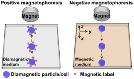
Using magnetic beads for microfluidic cell manipulation, often referred to as “positive magnetophoresis” or simply “magnetophoresis” (see Figure 1(a)), is an attractive technology when compared to other competing ones, such as dielectrophoresis.[12, 13, 14] Magnetic force is an “action at a distance”; it is not directly in contact with cells, minimizing potential hazardous effects that can reduce the viability of cells, which is typically associated with dielectrophoresis. This force depends on the magnetic moment of a particle or a cell and the gradient of external magnetic fields.[15-17] Underlying principles and applications of positive magnetophoresis have been previously reviewed.[12, 13, 14, 18] A typical application of positive magnetophoresis is the manipulation of magnetically labeled cells. It involves first labeling cells of interest with magnetic beads to render the cell-bead conjugate magnetic. Because the magnetization of beads is larger than its surrounding medium (e.g., water), cell-beads conjugates are magnetized under external fields and therefore move towards the location of field maxima. As a result, cells of interest can be manipulated (e.g., resulting in separation, trapping, focusing) from the rest of the sample. Microfluidic positive magnetophoresis has been developed to separate beads with different magnetic susceptibilities,[19, 20] and cells with different distributions of magnetic nanoparticles.[21] However, this technology has several limitations. First, it uses magnetic beads for labeling in order to achieve specific manipulation and separation. The process of incubating cells with magnetic beads can take up to several hours, and multiple washing steps are needed,[21] rendering the whole assay time-consuming and manually intensive. Second, manipulation specificity of positive magnetophoresis depends on the magnetic moment of beads or loading of magnetic nanoparticles in cells. Magnetic moments of beads can vary dramatically even in the same batch due to their manufacturing process.[17, 22] Third, loading of magnetic nanoparticles in cells is greatly affected by their endocytotic capacities or ligand-receptor interactions and can vary among the same type of cells.[21, 23] Clearly, it is highly beneficial to retain the benefits of positive magnetophoresis while eliminating the labeling step, in which cells and magnetic beads must be incubated together for a long period prior to manipulation.
Figure 1.

Working principles of positive and negative magnetophoresis and dominant forces. (a) Positive magnetophoresis – magnetization of diamagnetic particles/cells labeled with magnetic beads is larger than its surrounding medium; particles/cells move towards the location of field maxima when a magnetic field is applied. (b) Negative magnetophoresis – magnetization of diamagnetic particles/cells is less than its surrounding medium; particles/cells move towards the location of field minima when a magnetic field is applied. (c) Dominate forces include magnetic force F⃗m, hydrodynamic drag force F⃗h, gravitational force G⃗, and buoyancy force F⃗b on a particle in negative magnetophoresis. U⃗p is the velocity of the particle and U⃗f is the velocity of the medium flow.
A recent magnetic manipulative technique, termed “negative magnetophoresis” (also referred to as diamagnetophoresis) (see Figure 1(b)),[15] is label-free and can address the above-mentioned problems.[24, 25] The principle of negative magnetophoresis is exactly the opposite of positive magnetophoresis. Particles or cells to be manipulated in this case are less magnetic (diamagnetic in most cases)than that of their surrounding medium, which is typically a magnetic liquid such as a paramagnetic salt solution[26, 27] or a ferrofluid.[24, 28] Particles or cells placed inside a magnetic liquid act as “magnetic holes”.[29] An externally applied magnetic field gradient attracts the liquid medium, which causes the cells to be preferentially pushed away.[16] As such, particles or cells inside these magnetic liquids can be potentially manipulated towards a weaker field direction without the time-consuming labeling step. The force acting on them is named as magnetic buoyancy force, which is a body force and is proportional to the volume of particle or cell.[16] A typical application of negative magnetophoresis is size-based cell separation, which does not need any magnetic tags for labeling. Cells of different sizes are simply injected into a continuous-flow microfluidic channel filled with magnetic liquids. Balanced by viscous drag force, large cells experience more magnetic buoyancy force than smaller ones, resulting in a spatial separation between the two species at the end of the channel.[28, 30] The advantages of negative magnetophoresis include the following. First, it is a label-free manipulation, which can potentially reduce the time and cost associated with label-based assays. Second, a typical setup for negative magnetophoresis is very simple and low-cost, only requiring a microchannel and a permanent magnet in most cases. Third, magnetic liquids can potentially be made biocompatible,[25, 31] which may enable live cell manipulation for certain cell types. However, it is important to note that biocompatibility of magnetic liquids is still a work in progress. Both short-term viability and long-term cellular functions (e.g., proliferation, gene expression, and nanoparticle uptake) need to be carefully studied for each cell type to determine whether a specific magnetic liquid is truly biocompatible.
The goal of this article is to review the fundamental principles of negative magnetophoresis and its recent applications in microfluidic manipulation of particles and cells. The remaining sections of the article are structured as follows. First, we introduce the commonly used specificities of manipulation in magnetic liquids, which include size, density and magnetic property of particles and cells. Second, we review and compare the media used in negative magnetophoresis, which includes paramagnetic salt solutions and ferrofluids. Third, we summarize the existing microfluidic applications of negative magnetophoresis, including separation, focusing, trapping, etc., and compare their performance. In addition, we also discuss the biocompatibility of magnetic liquids that is critical for live cell manipulation. Finally, we present an outlook for this new and exciting research field.
2. Dominant Forces
The types of forces in microfluidic systems, especially in positive and negative magnetophoresis, have been summarized in several review articles.[13, 18] The most relevant ones among them for this review article are magnetic force, hydrodynamic viscous drag force, and gravitational/buoyant forces that are depicted in Figure 1(c). Other forces including surface DLVO (Derjaguin-Landau-Verwey-Overbeek) force, Brownian motion, particle and fluid interaction, and interparticle effects are secondary in nature; therefore, we neglect them in this review.[32]
2.1 Magnetic Force
A general expression for the magnetic force F⃗m on a magnetized body in a magnetic liquid under a magnetic field is shown in Equation (1).[16] Here μ0 = 4π × 10-7 H m-1 is the permeability of free space, V is the volume of the magnetized body, typically a spherical particle or cell with diameter of Dp, M⃗p is its magnetization (close to zero for most cells), M⃗f is magnetization of the magnetic liquid surrounding the body, and H⃗ is magnetic field strength at the center of the body.
| (1) |
For particle and cell manipulation in paramagnetic salt solutions or ferrofluids under weak magnetic fields, magnetizations of both the body M⃗p and the magnetic liquid M⃗f depend approximately linearly on the applied field, resulting in M⃗p = χpH⃗ and M⃗f = χfH⃗, where χp and χf are the dimensionless volume magnetic susceptibilities of the body and the magnetic liquid, respectively. Therefore, the magnetic force under a weak field approximation takes the form of Equation (2), which is often cited in the literature.[12, 13] Here B⃗ is magnetic flux density.
| (2) |
For particle and cell manipulation in ferrofluids under strong magnetic fields, Equation (2) is no longer valid as the magnetization of a superparamagnetic particle depends nonlinearly on the applied field, as does the magnetization of a ferrofluid. Both the superparamagnetic particle and ferrofluid can be modeled accurately by the classical Langevin theory. Langevin theory considers magnetic nanoparticles in a superparamagnetic particle and a ferrofluid as a collection of monodispersed and non-interacting magnetic dipoles.[16] This approach leads to the Langevin function of magnetization[16] in Equations (3) and (4). Here and . ϕp and ϕf are volume fractions of the magnetic materials, Mp,b and Mf,b are saturation moments of the bulk magnetic materials, and dp and df are diameters of nanoparticles in a superparamagnetic microparticle and a ferrofluid, respectively. κB is the Boltzmann constant, T is temperature.
| (3) |
| (4) |
In the case of positive magnetophoresis, magnetization of the superparamagnetic particle M⃗p is always larger than its surrounding medium M⃗f. Under a non-uniform magnetic field, the direction of magnetic force F⃗m on the particle is pointing towards field maxima. On the other hand, for negative magnetophoresis, magnetization of the particle or cell M⃗p is always less than its surrounding magnetic liquid M⃗f, and the direction of magnetic force F⃗m on the particle or cell is pointing towards field minima.
2.2 Hydrodynamic Viscous Drag Force
The Reynolds number in a typical microfluidic device is much less than 1, resulting in laminar flows. Hydrodynamic viscous drag force thus plays a significant role in particle and cell manipulation; its expression on a spherical particle is,
| (5) |
Here, η is the viscosity of magnetic liquids, U⃗p and U⃗f are velocity vectors of magnetic liquids and particles, respectively, fD is hydrodynamic drag force coefficient of a particle experiencing the effect of having a solid surface in its vicinity, which is often referred to as a “wall effect”. The function fD can be expressed in Equation (6) as a resistance function of hydrodynamic interaction between the particle and the surface. Its appearance indicates the particle experiences increased fluid viscosity as it moves closer to the surface.[33]
| (6) |
Here, Δ is the shortest distance between particle surface and solid surface.
In the case of ferrofluids as the surrounding medium, the magnetic nanoparticles tend to form a chain structure due to inter-particle interaction, leading to an increase of the overall liquid viscosity. This phenomenon is known as the magnetoviscous effect.[34] However, such an effect becomes pronounced only in highly concentrated ferrofluids. The volume concentration of ferrofluids in particle and cell manipulation, however, is on the order of 1%, and therefore the magnetoviscous effect can be neglected for future analysis.
2.3 Gravitational and Buoyant Forces
The net force of gravitational and buoyant forces on a spherical body can be expressed as,
| (7) |
Here, g⃗ is the direction of gravity, ρp and ρf are the densities of the particle or cell, and its surrounding magnetic liquids, respectively. Typically, particles and cells possess a density that is very close to that of magnetic liquids. As a result, the net force F⃗n is usually one order of magnitude lower than magnetic force F⃗m or hydrodynamic force F⃗h. However, the subtle difference of this force between two species with very similar densities was recently exploited for high-resolution particle and cell separation in magnetic liquids.[35-39] We will review its working principle in Section 4.2.
Due to the low Reynolds number and resulting laminar flow in microfluidic systems, inertial effects can be neglected. Therefore the dynamics of particles and cells in magnetic liquids are determined by the balance of all dominant forces,
| (8) |
Equation (8) yields the relative velocity of a spherical body in magnetic liquids,
| (9) |
It is clear from Equation (9) that the dynamics of a particle or a cell in magnetic liquids is determined by its physical properties, including size, density, as well as the contrast of magnetization between itself and surrounding medium. These three physical properties are currently being exploited for microfluidic applications using magnetic liquids. We will discuss the origins of these manipulation specificities and their applications in Section 4.
3. Magnetic Liquids
3.1. Paramagnetic Salt Solutions
Representative applications of negative magnetophoresis in microfluidics include cell and particle manipulation in either a paramagnetic salt solution or a ferrofluid. Several types of paramagnetic salt solutions are available for this purpose. They are generally formed with a paramagnetic metal and an organic chelating agent or halide. Solutions containing certain transition and lanthanide metals, such as Mn2+ and Gd3+, are paramagnetic due to their unpaired inner-shell electrons that can produce a magnetic moment. Chelating agents, such as diethylenetriaminepentaacetic acid (DTPA) and diethylenetriamine triacetic acid didecyldiacetamide (DTAD) can bind to these metal cations. Gd·DTPA is commonly used by Whitesides's and coworkers in experiments that involve proteins, since it is a cheap and a readily available paramagnetic solution used in magnetic resonance imaging (MRI), which does not denature proteins.[38, 40] Gadolinium based contrast agents (GBCAs) were introduced in 1984 to perform MRI scans on patients using Gd(DTPA)2-.[41] Gadolinium in all GBCAs is chelated to organic ligands to render the compound safe, as the free gadolinium ion is toxic to humans.[42] GBCAs are widely viewed as being safe to administer to patients with almost no adverse health effects. GBCAs such as gadavist (gadobutrol) have been used more recently in density based separation experiments as the paramagnetic medium of choice.[43, 44] When injected into human patients, most GBCAs are formulated in concentrations of 0.5-1 m, or administered at 0.1 mmol kg-1-0.3 mmol kg-1 of body weight.[42] When used in density based manipulation settings, it is used at concentrations between 25-250 mm.[43-45] Halide salts, such as MnCl2 and GdCl3 are more widely used in experiments when samples of interest do not dissolve in aqueous solutions.[37] They are also transparent so that particles or cells are visible in them. However, they have relatively high vapor pressure, which makes storing the solutions difficult, since they slowly lose volume over time. The loss of solvent also changes the concentration of the salt solution and affects its magnetic properties. Recently developed paramagnetic ionic liquids (PILs) have a low vapor pressure and do not evaporate easily.[46] PILs are a subset of ionic liquids that contains cation-anion mixtures and melt at or below 100 °C.[47] Typically, a combination of a sterically hindered organic cation and a metal-halide anion complex are used to create a PIL.[48] Some common metal-halide complexes include [GdCl6]3+, [DyCl6]3+, [HoCl6]3+, and [MnCl4]2+. As previously discussed, these metals are paramagnetic due their unpaired inner-shell electrons, and as a result, the ionic liquid containing these metals is paramagnetic as well. For example, 1-butyl-3-methylimidazolium tetrachloroferrate ([BMIM] [FeCl4]) is a common PIL.[46, 49] PILs have increased shelf life due to their low vapor pressure, low melting points, high thermal stability, and tunable properties.[46]
Generally speaking, a paramagnetic salt solution has relatively low volume magnetic susceptibility and magnetization. For example, manganese (II) chloride (MnCl2)'s solubility limit in water at room temperature is 1470 kg m-3,[50] corresponding to a molar concentration of 11.7 m. Its initial volume magnetic susceptibility is 9×10⁻⁴ at this solubility limit, while its magnetization is 1.4×10³ A m-1 and 1.4×10⁴ A m-1 at magnetic flux densities of 2 T and 20 T, respectively.[16] Commonly used concentrations of the paramagnetic salt solution in the published literature are in the range of 0.1-1 m, partly in order to achieve good biocompatibility for cell manipulation.[20, 26, 51-53] As a result, its typical susceptibility and magnetization are even lower than the above-mentioned values. Typical applications of a paramagnetic salt solution use either high magnetic fields generated from superconducting magnets[51, 53] or high field gradients from microfabricated ferromagnetic structures[27] to compensate for its low susceptibility and magnetization and achieved fast particle and cell manipulation.
3.2. Ferrofluids
Another type of magnetic liquid that has relatively high volume magnetic susceptibility and magnetization under fields generated by permanent magnets is ferrofluids. Ferrofluids are colloidal suspensions of magnetic nanoparticles, typically magnetite (Fe3O4) or maghemite (Fe2O3) with diameters of approximately 10 nm.[16] The nanoparticles are covered by either electrostatic or steric surfactants to keep them from aggregating and in suspension within a carrier medium. Ferrofluids can be prepared by simple chemical co-precipitation methods. Its synthesis usually involves co-precipitation of ferrous and ferric salts in an aqueous base solution, followed by an oxidation process.[16] Progress has also made towards developing biocompatible ferrofluids for MRI contrast agents.[54] For example, oleic acid coated iron oxide nanoparticles dispersed in chitosan were synthesized for MRI contrast agent,[55] and starch polymer coated magnetic nanoparticles were prepared for MRI tests in tumor targeting.[56] Ferrofluid hydrodynamics (ferrohydrodynamics), dealing with mechanics of ferrofluid motion under external magnetic fields, has been well studied since 1960s.[16] The fundamentals and applications of ferrohydrodynamics are reviewed and summarized in several books.[16, 57] In its applications to particle manipulation, an effective magnetic dipole moment within the diamagnetic object immersed in ferrofluids is induced. As a result, the object experiences a magnetic buoyancy force under a non-uniform magnetic field. This principle has been used to assemble particles.[29, 58]
The susceptibility and magnetization of a ferrofluid are tunable through controlling its concentration of magnetic materials. For example, the maximal volume fraction of a water-based magnetite ferrofluid is approximately 10%. Given the bulk magnetization of magnetite is 4.46×10⁵ A m-1, this ferrofluid's initial volume magnetic susceptibility is on the order of 1, and its saturation magnetization is on the order of 104 A m-1 under fields generated from a hand-held permanent magnet, both of which are significantly larger than the values of a paramagnetic salt solution. Better magnetic properties of the ferrofluid may enable its applications with the use of simple permanent magnets, instead of superconducting magnets or microfabricated ferromagnetic structures, for fast microfluidic manipulations.
Typical ferrofluids used in microfluidic applications are water-based. The issues of using water-based ferrofluids for particle or cell manipulation are two-fold. First, light diffraction from the high concentration of magnetic nanoparticles in ferrofluids makes it difficult to directly observe particles or cells. To solve this problem, microfluidic devices with shallow channels and ferrofluids with low solid volume fraction are needed. Second, biocompatible ferrofluids are necessary for live cell manipulation. For mammalian cells, materials, pH value, and surfactants of ferrofluids need to be rendered biocompatible, while at the same time the overall colloidal system of ferrofluids must be maintained. To satisfy these criteria, the materials of nanoparticles within ferrofluids need to be biocompatible, such as magnetite or maghemite. The pH value of ferrofluids needs to be compatible with cell culture and maintained around 7. Salt concentration, tonicity, and surfactant must be carefully chosen close to physiological conditions to reduce cell death. Progress has been made towards synthesizing biocompatible ferrofluids, which will be reviewed in Section 4.4.2.
4. Review of Applications
4.1. Size Based Manipulation
Size difference among particles or cells is the most frequently used manipulation specificity in magnetic liquids. Equation (9) indicates that particles or cells with larger size (volume) move faster in magnetic liquids than smaller ones, provided that they share the same magnetic properties, and their velocities are perpendicular to the direction of gravity. Larger particles or cells move faster because larger particles or cells experience much more magnetic forces than smaller ones, as the magnetic forces are proportional to the volume, while the hydrodynamic viscous drag force, on the other hand, scales only with the diameter. This is the working principle for size based manipulation in magnetic liquids. A schematic of continuous-flow size based manipulation in magnetic liquids is also shown in Figure 2(a). Cells mixed with magnetic liquids are introduced into a microfluidic channel and hydrodynamically focused by a sheath flow. Once entering the separation region, deflection of cells from their flow paths occurs because of the magnetic forces on them under a non-uniform magnetic field. At the end of the channel, larger cells are deflected into a different outlet than smaller ones, as shown in Figure 2(a). Through different magnetic field patterns, size based manipulation were also applied on particle and cell trapping (Figure 2(b)) and focusing (Figure 2(c)). We now review its existing microfluidic applications using either paramagnetic salt solutions or ferrofluids.
Figure 2.

Schematic working principles of (a) size based manipulation, (b) particle/cell trapping, (c) particle/cell focusing, and (d) density based manipulation in magnetic liquids. The particle on the right is denser than the one on the left, while the middle particle has the same density as it surrounding medium. (e) Magnetization contrast based manipulation. The orange particle is more magnetic than the medium, while the green particle is less magnetic than the medium. U⃗1 and U⃗2 represent the direction and the magnitude of the particle's or cell's velocity. Arrow and cross indicates the direction of gravity G⃗. The color map depicts distributions of magnetic field strength, from maxima Bmax (orange) to minima Bmin (blue).
4.1.1. Paramagnetic Salt Solution Based Manipulation
Separation
Size differences between particles or cells are often used for separation in paramagnetic salt solutions. Their working mechanisms and performances are summarized in Figure 3 and Table 1. Tarn et al.[51] applied diamagnetophoresis for a continuous separation of diamagnetic particles in MnCl2 solution (0.48 and 0.79 m), as shown in Figure 3(a). They examined the separation of 5 μm and 10 μm diameter particles in different concentrations of this salt solution and concluded that better separation performance could be achieved with a higher concentration of MnCl2 solution in a superconducting magnet with an external magnetic flux of 10 T. Kawano et al.[59] developed a two-dimensional capillary cell to separate particles in MnCl2 solution (1 m) using triangular shaped pole pieces, as shown in Figure 3(b). Fractionation of particles with different diameters (1, 3, and 6 μm) was achieved in a superconducting magnet. They also fractionated deoxygenated and non-deoxygenated red blood cells using a wider capillary cell. They showed that deoxygenated red blood cells had a large variation of the magnetic susceptibility. Vojtíšek et al.[53] developed two microfluidic devices, which were inserted into the bores of superconducting magnets, to separate particles of different sizes (5.33 and 10.32 μm). They concluded that diamagnetic repulsion of particles could be enhanced by increasing particle size, concentration of paramagnetic salt solution, and magnetic field strength and gradient. They further demonstrated deflection of microbubbles suspended in MnCl2 (0.48 m). Peyman et al.[26] developed a versatile microfluidic device (see Figure 3(c)) for particle separation in a MnCl2 solution (0.79 m). The device was used to separate 5 μm and 10 μm particles. Shen et al.[27] developed a microfluidic system with microfabricated nickel microstructures embedded in a microchannel, as shown in Figure 3(d). The system generated sufficient magnetic repulsion forces for the separation of cells and particles with different sizes. They demonstrated the separation of U937 cells (human histolytic lymphoma monocytes) from red blood cells (RBCs) with over 90% purity and moderate throughput of 1×10⁵ cells h-1 in a Gd·DTPA solution.
Figure 3.

Schematic representations of size based separation in paramagnetic salt solutions. (a) A continuous separation of diamagnetic particles in MnCl2 solution in a superconducting magnet. Reproduced from ref.[51] (b) Separation of particles in MnCl2 solution using triangular shaped pole pieces in a capillary. Reproduced from ref.[59] (c) Deflection of diamagnetic particles by a permanent magnet in a microfluidic system. Reproduced from ref.[26] (d) Microfluidic separation of diamagnetic particles/cells with a microfabricated nickel microstructures. Reproduced from ref.[27] Blue arrow in each figure indicates the flow direction.
Table 1.
Summary of sized based manipulation in paramagnetic salt solutions.
| Magnetic liquids | Magnetic fields | Applications | Efficiency | Throughput | References |
|---|---|---|---|---|---|
| MnCl2 | Superconducting magnet | Particle separation | NA | ∼105 particles h-1 | [51] |
| MnCl2 | Superconducting magnet | Particle separation | 100% | ∼105 particles h-1 | [53] |
| MnCl2 | Superconducting magnet | Particle/cell separation | NA | NA | [59] |
| MnCl2 | Permanent magnet | Particle trapping | NA | NA | [62] |
| MnCl2 | Permanent magnet | Particle trapping | 0-100% | NA | [63] |
| MnCl2 | Permanent magnet and iron pieces | Particle/cell trapping | 0-100% | NA | [64] |
| MnCl2 | Permanent magnet | Particle trapping | 100% | ∼104 particles h-1 | [52] |
| MnCl2 | Permanent magnet | Particle trapping/ Particle focusing/ Particle separation |
100% NA 100% |
∼103 particles h-1/ ∼104 particles h-1/ ∼104 particles h-1 |
[26] |
| MnCl2 | Permanent magnet | Particle transport | NA | ∼105 particles h-1 | [61] |
| Gd·DTPA | Permanent magnet | Cell focusing | 40% | NA | [20] |
| Gd·DTPA | Permanent magnet and Ni microstructure | Cell separation | 90% purity | 105 cells h-1 | [27] |
| Gd·DTPA | Permanent magnet | Particle/cell trapping | NA | NA | [31] |
Focusing
Focusing particles and cells[60] into a narrow stream in a continuous-flow manner is critical for downstream analytical procedures in microfluidic systems. In order to achieve focusing in magnetic liquids, a local magnetic field minima needs to be created in the microfluidic device, typically via a pair of opposing magnets. Diamagnetic particles and cells suspended in magnetic liquids, experiencing magnetic buoyancy force as they flow through the channel, can then be focused into narrower streams for further processing. Working mechanisms and performances of existing focusing schemes using paramagnetic salt solutions are summarized in Figure 4 and Table 1. Peyman et al.[26] developed a system with a capillary and a pair of magnets to focus continuously diamagnetic particles (10 μm) into a narrow stream, as shown in Figure 4(a). They demonstrated that the diamagnetic forces were capable of focusing particles to the center of a fused silica capillary at a flow rate of 40 μL h-1. Rodríguez-Villarreal et al.[20] developed a diamagnetic repulsion setup to focus particles (10 and 20 μm) and HaCaT cells (spontaneously immortalized human skin keratinocyte) in a continuous-flow fashion. They optimized focusing parameters including magnetic susceptibility of the medium, flow rate, particle size, and exposure time of particles in the magnetic field. They demonstrated that 40% of HaCaT cells could then be focused in paramagnetic media (39 mm Gd·DTPA) in their setup. Zhu et al.[61] studied the transport of diamagnetic particles (5, 10, 15 μm) in a MnCl2 solution (0.04, 0.2, 1 m). They looked into the effects of particle position, size, flow rate and concentration of salt solution on particle deflection.
Figure 4.

Schematic representations of size based focusing and trapping in paramagnetic salt solutions. (a) Focusing of diamagnetic particles in a capillary with a pair of magnets. Reproduced from ref.[26] (b) Trapping of diamagnetic particles and living cells using a three-dimensional magnetic trap. Reproduced from ref.[31] (c) Trapping of diamagnetic polymer particles in a capillary. Reproduced from ref.[26] (d) Simultaneous trapping of diamagnetic and magnetic particles in a capillary. Reproduced from ref.[52] Blue arrows in figures indicate the flow direction.
Trapping and concentration
Trapping and concentrating particles or cells are conceptually similar to focusing, except in this case, the flow in microfluidic devices is static or very small so that the magnetic buoyancy force is able to retain particles or cells at the locations of magnetic field minima. Its working mechanisms and performance are summarized in Figure 4 and Table 1. Watarai et al.[62] studied the magnetophoretic migration behavior of diamagnetic particles in a paramagnetic salt solution (0.6 m MnCl2). Migration velocity and direction of various diamagnetic particles (1.5, 3, 6, and 9 μm) were investigated in a sealed capillary tube sandwiched by two permanent magnets. They concluded that particle migration was affected by magnetic buoyancy force. A device was then developed to achieve the trapping of diamagnetic polystyrene particles with different sizes (2.77, 5.87, 9.14 μm).[63] Later on, Watarai et al.[64] developed a square fused-silica capillary magnetophoretic device to trap RBCs in MnCl2 solution (0.1 m). Winkleman et al.[31] demonstrated the trapping of diamagnetic particles and different types of living cells in a paramagnetic salt solution using a three-dimensional magnetic trap, as shown in Figure 4(b). They also examined the biocompatibility of the gadolinium solution. They also showed that Gd·DTPA possessed minimal detrimental effect to the viability of both fibroblast cells (NIH 3T3) and yeast cells (Saccharomyces cerevisiae) at a concentration of 40 mm. Peyman et al.[26] developed a device to trap particles (10 μm) in a paramagnetic salt solution (0.79 m MnCl2). Figure 4(c) shows two pairs of permanent magnets with opposite poles facing each other, which were used to generate a magnetic gradient to trap streptavidin coated diamagnetic particles in a capillary. Tarn et al.[52] developed a simple concentration method that could achieve simultaneous trapping of diamagnetic and magnetic microparticles with a 100% efficiency in a capillary with a pair of magnets, as shown in Figure 4(d). After trapping, biochemical assays were examined on the particles to achieve multiple analyses.
4.1.2. Ferrofluid Based Manipulation
Separation
Ferrofluids, which have a relatively high volume magnetic susceptibility and magnetization under fields generated by permanent magnets, are frequently used as the carrier medium to separate particles and cells with different sizes. Their working mechanisms and performance are summarized in Figure 5 and Table 2. Zhu et al.[28] developed a label-free separation scheme using a commercial ferrofluid (EMG 408 from Ferrotec Corp., Santa Clara, CA, USA) to separate continuously binary mixtures of diamagnetic particles (1 and 9.9, 1.9 and 9.9, 3.1 and 9.9 μm) in a microfluidic device, as shown in Figure 5(a). The magnetic field gradient created by permanent magnets in the microchannel made it low-cost and efficient to conduct size-based separation with a throughput of 105 particles h-1 and close to 100% separation efficiency. Later on, Zhu et al.[30] ferrohydrodynamically separated Escherichia coli from Saccharomyces cerevisiae cells using the same commercial ferrofluid with high throughput (∼107 cells h-1) and efficiency (∼100%) in a continuous-flow manner. They used a three-dimensional analytical model to predict cells' trajectories. The simulated cell dynamics agreed well with the experimental results. Furthermore, they showed this particular commercial ferrofluid was not detrimental to the viability of both cell types after 2 h of exposure. Recently, Zhao and Zhu et al.[65] demonstrated the separation of HeLa cells (cervical carcinoma) and blood cells in a custom-made biocompatible ferrofluid with a moderate throughput (∼106 cells h-1) and high separation efficiency (> 99%). Liang et al.[66] separated binary mixture of particles (5 and 15 μm) in EMG 408 ferrofluids. Zeng et al.[67] achieved the separation of particles and live yeast cells in EMG 408 ferrofluids using two offset permanent magnets, as shown in Figure 5(b). One of the magnets was used to focus particle mixtures into a narrow stream, and the other was used to separate them. They examined the effects of flow rate and magnet-microchannel distance on the particle separation. Separation distance between two particle streams could be increased by decreasing the flow speed or magnet-microchannel distance. They also demonstrated the separation of live yeast cells from particles.
Figure 5.

Schematic representations of size based separation in ferrofluids. (a) Continuous separation of binary mixtures of diamagnetic particles in a microfluidic device. Reproduced from ref.[28] (b) Separation of particles and live yeast cells in a ferrofluid using two offset permanent magnets. Reproduced from ref.[67] (c) Separation of bacteria and blood cells in a biocompatible ferrofluid using traveling-wave magnetic fields. Reproduced from ref.[24] (e) Nanocytometry particle sorting device. Reproduced from ref.[68] Blue arrows in figures indicate the flow direction.
Table 2.
Summary of sized based manipulation in ferrofluids.
| Magnetic liquids | Initial magnetic susceptibilities | Saturation magnetizations [mT] | Magnetic fields | Applications | Efficiency | Throughput | References |
|---|---|---|---|---|---|---|---|
| 1 EMG 408 ferrofluid | 0.5 | 6.6 | Permanent magnet | Particle separation | 100% | ∼105 particles h-1 | [28] |
| 1 EMG 408 ferrofluid | 0.5 | 6.6 | Permanent magnet | Particle/cell separation | 100% | ∼107 particles h-1 | [30] |
| 1 EMG 408 ferrofluid | 0.5 | 6.6 | Permanent magnet | Particle separation | NA | NA | [66] |
| 1 EMG 408 ferrofluid | 0.5 | 6.6 | Permanent magnet | Particle/cell separation | NA | NA | [67] |
| 1 EMG 408 ferrofluid | 0.5 | 6.6 | Permanent magnet | Particle focusing | NA | NA | [69], [70], [72] |
| 1 EMG 408 ferrofluid | 0.5 | 6.6 | Permanent magnet | Particle/cell concentration | NA | NA | [73] |
| 1 EMG 408 ferrofluid | 0.5 | 6.6 | Permanent magnet | Particle concentration | NA | ∼105 particles h-1 | [74] |
| 1 EMG 408 ferrofluid | 0.5 | 6.6 | Permanent magnet | Particle trapping | NA | ∼105 particles h-1 | [75] |
| 1 EMG 408 ferrofluid | 0.5 | 6.6 | Permanent magnet | Particle/cell focusing | NA | ∼105 cells h-1 | [71] |
| 1 EMG 408 ferrofluid | 0.5 | 6.6 | Permanent magnet | Particle transport | NA | NA | [32] |
| 1 EMG 705 ferrofluid | 4.04 | 22 | Permanent magnet | Droplet fabrication and manipulation | NA | NA | [77] |
| 1 EMG 700 ferrofluid | 12.57 | 32.5 | Traveling-wave magnetic fields from copper electrodes | Particle separation | 99% | 3 × 10⁴ particles s-1 mm-2 | [68] |
| 2 Citrate stabilized ferrofluid | NA | NA | Traveling-wave magnetic fields from microfabricated electrodes | Cell separation | 75.2% | NA (static flow system) | [24] |
| 2 Graft copolymer functionalized ferrofluid | NA | NA | Permanent magnet | Cell separation | >99% | ∼106 cells h-1 | [65] |
| 3 MF01 ferrofluid | 0.2 | 50 | Permanent magnet | Droplet manipulation | NA | NA | [76] |
Commercially available from Ferrotec Corp.,
custom-made ferrofluids, and
commercially available from Sunrise Ferrofluid Technological Ltd.
Separation of particles and cells in ferrofluids were also achieved using traveling-wave magnetic fields generated from microfabricated electrodes. Kose et al.[24] used a traveling-wave magnetic field for particle and cell separation, as shown in Figure 5(c). In their setup, the spatially-traveling and timely-alternating magnetic field was generated by microfabricated electrodes embedded at the bottom of a microchannel. The electrodes were made using a single layer of copper on a printed circuit board. They were then wire bonded in a pattern that resulted in a 90-degree current phase difference between each adjacent electrode. The resulting fundamental component of the magnetic field in the channel is a travelling wave, similar to the travelling excitation over the stator surface in an electric motor. In their microfluidic system, the flow is static, and the direction of the traveling-wave was parallel to the moving directions of particles and cells. Depending on their size, the particles or cells were either trapped or moving continuously, resulting in a spatial separation in the channel. They demonstrated the separation of bacterial and blood cells with a 95.7% efficiency, and separation of healthy red blood cells from sickle cells, with an efficiency of 75.2% in a citrate stabilized biocompatible ferrofluid. A similar principle was also applied in a microfluidic device called a nanocytometer that could separate binary (2.2 and 4.8 μm) and ternary (2.2, 4.8, 9.9 μm) mixtures of diamagnetic particles in a commercial EMG 700 ferrofluids by Kose et al.[68], as shown in Figure 5(d). In this case, the direction of the traveling-wave was perpendicular to the moving particle. As a result, the particles could be separated in a continuous flow with higher throughput.
Focusing
Zhu et al.[69] developed a microfluidic particle focusing scheme within EMG 408 ferrofluids. Focusing of particles with different sizes (4.8, 5.8, 7.3 μm) at various flow rates was demonstrated, as shown in Figure 6(a). An analytical model was developed in this study to simulate the distribution of a magnetic field, magnetic force and trajectories of particles within the device. A three-dimensional diamagnetic microparticle focusing scheme in EMG 408 ferrofluids was presented by Liang et al.[70] Particles were magnetically deflected both in a horizontal and vertical direction through the cross-section of the channel to form a focused stream. Ferrofluid concentration, particle size, and flow rate were demonstrated to have significant effects on particle deflection. They developed a numerical model to predict microparticle deflection in ferrofluid flows, too. Zeng et al.[71] conducted a theoretical and experimental study on the focusing of diamagnetic particles with diameters of 5 μm and yeast cells in EMG 408 ferrofluids. Two sets of opposing permanent magnets were embedded into the microchannel to achieve diamagnetic focusing. The effectiveness of focusing was studied at different flow rates and different particle sizes. Furthermore, cell viability results demonstrated that this focusing method in ferrofluid was biocompatible with yeast cells. A simpler setup with only one magnet was used by Liang et al.[72] to focus particles, as shown in Figure 6(b).
Figure 6.

Schematic representations of size based manipulation (focusing, trapping, concentration, droplet manipulation) in ferrofluids. (a) Microfluidic particle focusing in ferrofluids. Reproduced from ref.[69] (b) Focusing particles in a ferrofluid flow using a single permanent magnet. Reproduced from ref.[72] (c) Magnetic concentration of particles and cells using attracting magnets. Reproduced from ref.[73] (d) Diamagnetic particle concentration in ferrofluids with an asymmetric magnet configuration. Reproduced from ref.[74] (e) Simultaneous trapping and pre-concentrating of diamagnetic and magnetic particles in ferrofluids in a T-junction channel. Reproduced from ref.[75] (f) Manipulation of aqueous droplets in ferrofluids. Reproduced from ref.[76] Blue arrow in each figure indicates the flow direction.
Trapping and concentration
Zeng et al.[73] presented a simple device configuration that was used for magnetic concentration of particles and live yeast cells in EMG 408 ferrofluids flow using attracting magnets, as shown in Figure 6(c). The magnet-magnet distance and flow rate effects on the concentration of particles were studied. The biocompatibility of this ferrofluid was also tested, indicating that it had minimum effects on the viability of yeast cells. Wilbanks et al.[74] investigated the concentration of diamagnetic particles in EMG 408 ferrofluid using an asymmetric magnet configuration, as shown in Figure 6(d). With such a configuration, they achieved a stronger magnetic force and thus higher ferrofluid flow rate for continuous particle trapping. Zhou et al.[75] used a single permanent magnet and a T-junction microchannel to trap simultaneously and pre-concentrate diamagnetic and magnetic particles in EMG 408 ferrofluids, as shown in Figure 6(e). Diamagnetic particles experienced negative magnetophoresis and were trapped in the main channel (T-junction region). At the same time, magnetic particles experienced positive magnetophoresis and were concentrated in the branched channel next to the magnet.
Droplet manipulation
In addition to particles and cells, droplets were also manipulated in non-mixable ferrofluids. Zhang et al.[76] combined magnetic force and flow shear force to manipulate aqueous droplets based on their sizes within a commercial engine oil-based ferrofluid in a microfluidic device, as depicted in Figure 6(f). These droplets could be deflected, split, trapped, released, fused and exchanged for medium to achieve comprehensive manipulation. Recently, Zhu et al.[77] developed a magnetic-field-assisted method to generate and polymerize nonspherical particles in a microfluidic device. Monomer continuous flow phase formed droplets within an aqueous dispersed ferrofluid phase; they were then stretched or compressed into non-spherical shapes by magnetic fields.
Modeling efforts
Modeling is important for device design and optimization using negative magnetophoresis principle. Two types of models exist, including analytical models and numerical models. Analytical models were first developed by Furlani's group to enable accurate and fast parametric analysis of large-scale magnetophoretic systems.[78] Recently, Zhu et al.[32] developed a two-dimensional analytical model of microfluidic transport of diamagnetic particles and cells in ferrofluids. This model took into account important design parameters including particle size, property of ferrofluids, magnetic field distribution, dimension of microchannel, and fluid flow rate. The simplicity and versatility of this analytical model made it useful for quick optimizations of future size based separation devices. They also validated the model using a microfluidic device. Later on, a three-dimensional analytical model was developed by Cheng et al.[79] to provide more precise estimate of dynamics of diamagnetic particles in magnetic liquids. In this model, the effects of magnetic field and force in the direction perpendicular to the moving particle, and channel depth, were taken into consideration. As a result, the model could predict three-dimensional magnetic field and force, hydrodynamic drag force, flow profiles, particle deflection, particle residual time and particle velocity in simple microfluidic systems. Han et al.[80] developed a three-dimensional numerical model for the transport of diamagnetic particles in magnetic liquids. Although the numerical model required higher demand for computing power and time, it could be applied to a broader range of microfluidic systems with complex configurations of channels and magnets.
4.2. Density Based Manipulation
Paramagnetic salt solutions were often used in separating objects with different densities in static-flow systems. This type of separation is typically referred to as magnetic levitation, or “MagLev”.[40, 81, 82] Negative magnetophoresis is the driving force behind magnetic levitation. Objects placed in a paramagnetic salt solution between two opposing magnets tend to migrate towards and stay at the location of magnetic field minima, which are on the centerline between the two magnets, as shown in Figure 2(d). Depending on their relative density to surrounding medium, objects will then relocate along the direction of gravity. Based on Equation (9), if the objects are denser than the medium (ρp > ρf), a relative velocity of objects to medium (U⃗p– U⃗f) is induced so that the objects will migrate and reach an equilibrium height that is below the centerline between magnets. If the objects are less dense than the medium (ρp < ρf), the objects will float to a location that is above the centerline between the magnets. If the objects have exactly the same density as the medium (ρp = ρf), they will rest on the centerline between magnets.
Density based manipulation was first utilized in the 1960s as a way to separate minerals, metals, and plastics from one another when placed in a ferrofluid or a paramagnetic salt solution.[37] This technology was later expanded in the 1990s to levitate various objects through the works of Beaugnon and Tournier,[83, 84] Weilert et al.,[85] and others.[86] These experiments often relied on large non-uniform magnetic fields to levitate liquids, solids, and biological specimens. Using the same principles, several components in magnetic liquids can be separated from one another. Separation occurs when diamagnetic objects placed in a magnetic liquid have different buoyancy forces acting on them, due to the difference in their densities. On the other hand, magnetic forces acting upon these objects only depend on their size, magnetic field, and the contrast of susceptibilities between the objects and the paramagnetic carrier. If the size and susceptibility of these objects are kept the same, diamagnetic objects of different densities in the same magnetic liquid can be separated purely based on their density differences as shown in Figure 7(a).[37]
Figure 7.

Schematic representations of density based manipulation. (a) Magnetic levitation platform (“MagLev”) for measuring densities. Reproduced from ref.[37] (b) Magnetic levitation device used for monitoring solid-supported reactions. Reproduced from ref.[36] (c) Microfluidic separation of particles with different densities. Blue arrow indicates the flow direction. Reproduced from ref.[35] (d) Magnetic levitation based device (“MagDense”) for determination of cell densities. Reproduced from ref.[39]
Density based manipulation has generated a wide range of applications recently. It was used for education and teaching reaction kinetics,[81] determination of differences among chemical derivatives,[36] protein analysis,[38, 40, 87], food analysis.[82] flow-based separation in microfluidic devices,[35] and density determination of cells.[39, 43] The most popular setup of density based separation is to create a custom fitting device that will hold strong permanent magnets in place, while a vial is placed in between them. The vial in between the magnets is filled with a paramagnetic medium so that any diamagnetic object placed in the vial will experience negative magnetophoresis. The applications of density based manipulation were summarized in Table 3.
Table 3.
Summary of density based manipulation.
| Magnetic liquids | Applications | Flow-based | Analytes | Performance | References |
|---|---|---|---|---|---|
| 1 MnCl2 GdCl3 | Density measurements | No | Foods and liquids | Density accuracy of ±0.0002 to ±0.02 g mL-1 | [37] |
| 1 GdCl3 | Teaching reaction Kinetics | No | Leucine on solid supports and amine derivatives | Experiment Performed in Approximately 1 h | [81] |
| 1 GdCl3 | Compound identification and reaction monitoring | No | Amine derivatives on polystyrene supports | Derivative identified in 15 min | [36] |
| 1 MnCl2 GdCl3 Gd·DTAD | Density measurements and food identification | No | Foods and liquids | 1 pL to 1 mL sample volumes | [82] |
| 1 GdDTPA | Protein analysis | No | BCA on PEGA supports | Real time protein quantification in several hours | [38] |
| 1 GdDTPA | Protein analysis | No | BCA/sulfonamide on PEGA supports | Determination of protein diffusion coefficients | [40] |
| 1 GdDTPA | Fabrication of living material | No | Hydrogel and cell seeded microbeads | Contactless spatial arrangement of living material | [90] |
| 2 MnCl2 MnSO4 | Protein analysis and immunoassays | No | Biotin and streptavidin on polystyrene supports | Improved real time protein quantification within 1 h | [87] |
| 2 Na2S2O | Cell monitoring | No | RBCs, WBCs, and PMNs | Real time morphological and spatial monitoring of cells | [39] |
| 2 Gd solution (gadavist) | Cell density measurements | No | RBCs, WBCs, and various cancer cell lines | Density resolution of ±0.0001 g mL-1 | [43] |
| 2 Gd solution (gadavist) | Microsphere density measurements | No | Polystyrene supports | Digital density measurements in under 6 min | [44] |
| 2 GdCl3 Gd·DTPA | Flow-based density separation | Yes | Microsphere supports | 0.10 to 0.25 μL min-1 flow rates | [35] |
| 2 Gd solution (gadavist) | Sickle cell anemia detection | No | RBCs | Results in 10 min | [91] |
| 2 Gd solution (gadavist) | Blood count test | No | RBCs and WBCs | Blood counts within 15 min | [45] |
Non-microfluidic manipulation and
microfluidic manipulation.
4.2.1. Non-Microfluidic Manipulation
Historically, many magnetic levitation experiments were performed by creating a non-uniform magnetic field. Beaugnon and Tournier demonstrated that any diamagnetic organic material could be levitated through such a method. They achieved such a field by using superconducting solenoids which could create a field gradient as high as 2000 T2 m-1.[84] Weilert et al.[85] levitated liquid drops of helium in a similar manner using solenoids. Their experiments demonstrated that drops helium were able to remain in contact with one another without coalescing. They later attested this phenomena to the slow evaporation of the helium forming a layer of vapor between the two drops, thus producing a layer similar to that in the Leidenfrost effect.[88] Most famously, Berry and Geim used the same solenoid-based magnetic levitation to levitate a frog.[89] These experiments demonstrated how a diamagnetic object could be levitated and reach a stable equilibrium. Nowadays, magnetic levitation can be performed without superconducting solenoids and requires only a small and inexpensive set of equipment.
Many modern density based manipulation methods follow the previously described setup, in which a vial is placed in between a custom fitting device with permanent magnets – a non-flow based method. This is often referred to as magnetic levitation, or “MagLev”. Many fundamental aspects of magnetic levitation were explored by Mirica et al.[37] One important characteristic of MagLev is the dependency on size for the time of separation. Larger objects reach an equilibrium height faster than smaller objects. Mirica et al.[36] showed an application of measuring density over time with MagLev in Figure 7(b). Microsphere solid support resins containing small molecules were placed into a 650 mm GdCl3 solution. The small molecule would react with different amine derivatives, affecting the density of microspheres and their eventual height. Monitoring this change in density over time allowed for an easy way to monitor reaction progress and to discern compounds. Shortly after, the same group[82] developed a new application for MagLev involving food analysis. They demonstrated that foods with a higher fat content levitated higher than those with a lower fat content. Benz et al.[81] have used MagLev to aid in teaching reaction kinetics at the undergraduate level. In a simple MagLev experiment, they reacted leucine covered solid support resins with various amine derivatives in 590 mm GdCl3. Overtime a denser product formed on the solid support, and by monitoring the levitation height over time, the reaction progress could be observed.
Another common application of non-flow MagLev is protein analysis. Because many biochemical studies rely on solid-supported chemistry,[36] MagLev proves to be a useful tool for analyzing proteins using microspheres. Shapiro et al.[38, 40] used density based separation to quantify the amount of proteins in solution and to determine binding affinities of a protein to different small molecule targets.
Tasoglu et al.[90] demonstrated the use of magnetic levitation to create small soft living material. Hydrogels and cell seeded microbeads placed in 10, 50, or 100 mm Gd3+ solution would tend towards magnetic minima, and as such could be directed to construct a desired structure. By utilizing the magnetic field created by cheap NdFeB magnets, these living building blocks can be arranged in almost any desired spatial arrangement without the need for electricity or physical contact.
4.2.2. Microfluidic Manipulation
Microfluidic manipulation follows the same principle as non-microfluidic manipulation in that a container is placed in a custom fitting device with permanent magnets; however, microfluidic manipulation works with a much smaller container and often deals with smaller samples, such as single cells. Winkleman et al.[35] developed a flow-based microfluidic device capable of separating particles of various densities, as shown in Figure 7(c). Using this device, they were able to separate particles with different densities. Depending on the flow rate, separation time could occur between a few min and an h. Using a non-flow method, Subramaniam et al.[87] utilized MagLev to quantify the amount of protein in solution and to perform immunoassays. They used a density amplified MagLev process that could determine the presence of neomycin in milk and the presence of several viral antibodies in vitro.
Cellular properties and cellular morphological changes can be analyzed using microfluidic based density separation. Tasoglu et al.[39] used magnetic levitation as a method to differentiate cell types from each another and to monitor cell responses to stimuli, based on eventual equilibrium heights, as shown in Figure 7(d). Healthy and sickle RBCs were placed into 10 mm sodium metabisulfite (Na2S2O5) and their equilibrium heights were compared to each another. Sickle RBCs reached a final equilibrium height that was easily distinguishable from healthy RBCs, giving an effective method to determine normal cells from sickle cells. Polymorphonuclear leukocytes (PMNs) were placed into 30 mm Gd3+ and activated with phorbol 12-myristate 13-acetate (PMA). Activated PMNs would reach a different equilibrium height from resting PMNs, allowing for morphological monitoring to be achieved. Cellular densities were determined by Durmus et al.[43] by placing several different mammalian cells into fetal bovine serum (FBS) with 30 mm Gd3+. Each cell density was determined in a solution consisting of a single cell type. Average measured densities of 1.109 and 1.088 g mL-1 were found for RBCs and white blood cells (WBCs), respectively. It was also determined that this setup for cellular separation, called “MagDense,” was able to determine the density of colorectal cancer cells to be 1.063 ± 0.007 g mL-1 and 1.084 ± 0.012 g mL-1, for HCT116 (colorectal carcinoma) and HT29 (colorectal adenocarcinoma) cell lines, respectively. The authors concluded that MagDense was a possible method to discern circulating tumor cells from whole blood due to these density discrepancies, because MagDense had a resolution range of 1×10⁻⁴ g ml-1 to 5.5×10⁻⁴ g mL-1.
More recently, Knowlton et al.[44] developed a novel setup for magnetic levitation, which consisted of a smartphone, 3D-printed lens, small capillary tube, and permanent magnets. The setup used a custom smart-phone application on an Android operating system to detect different equilibrium heights of particles and estimate their densities. They found that this apparatus was able to work accurately in a density range of 0.96-1.09 g mL-1, using various concentrations of gadolinium solution between 25 and 200 mm, with equilibration times of 6 min or shorter. Using a similar smartphone platform called Sickle Cell Tester, Knowlton et al.[91] tested RBCs for sickle cell anemia. In this study, they used the same gadolinium solution varying at concentrations between 25 and 200 mm. After exposing healthy control RBCs and diseased RBCs to sodium metabisulfite, the diseased RBCs gained a noticeable amount of density due to experiencing more dehydration and deoxygenation compared to healthy RBCs. This density discrepancy in turn was recognized by the Sickle Cell Tester, which allows for a diagnosis to be made. Baday et al.[45] also used smartphone imaging with magnetic levitation (i-LEV) to perform blood count tests. RBCs and WBCs in a finger prick aliquot of blood placed in a microcapillary with 30 mm of gadolinium solution were separated using permanent NdFeB magnets. After 15 min of equilibration time, the custom smartphone software could analyze the width of the blood band which resulted from the separated RBCs and WBCs to perform blood counts.
4.3. Magnetization Contrast Based Manipulation
Equation (9) also shows that the contrast of magnetization between particle/cell and its surrounding magnetic liquid plays an important role in their dynamics. As the contrast increases, the magnitude of velocity goes up. This enables exploiting magnetization contrast between fluids and particles/cells as a manipulation specificity in two different ways. For example, if there exist two types of particles/cells with magnetizations of M⃗p1 and M⃗p2 in a magnetic liquid with magnetization of M⃗f, and if M⃗f is between M⃗p1 and M⃗p2, i.e., when the condition of M⃗p1 > M⃗f > M⃗p2 is met, magnetic force will attract Type 1 particles/cells towards field maxima while the magnetic force pushes Type 2 particles/cells towards field minima, as shown in Figure 2(e). In this way, particles can be distinguished and separated solely based on their magnetizations in a simple microfluidic channel. It should be noted here that the volume of particles now only affects the magnitude, but not the direction of magnetic forces. In another example, one can create a concentration gradient of magnetic liquids in a channel so that particles/cells with magnetizations of M⃗p will naturally migrate towards the location where M⃗p = M⃗f, in order to minimize the magnetic force. The final location of the particles/cells can be used to measure their magnetic susceptibilities.
Corresponding to the first example, ferrofluids was used to create both positive and negative magnetophoresis in one system. Liang et al.[92] used a ferrofluid to separate 2.85 μm diamagnetic particles and 10 μm magnetic particles in a T-shaped channel. The magnetization of this ferrofluid was larger than that of diamagnetic particles, but lower than that of magnetic particles. As a result, 10 μm magnetic particles were attracted towards the magnet, while 2.85 μm diamagnetic particles were pushed away. Zhu et al.[93] combined both positive and negative magnetophoresis in a ferrofluid to separate magnetic and diamagnetic particles of similar sizes (7-8 μm), as shown in Figure 8(b). Moreover, they chose a ferrofluid with its magnetization falling in between the magnetizations of two different types of magnetic particles (2.8 μm and strongly magnetic; 8.2 μm and weakly magnetic particles) and successfully separated them.
Figure 8.

Schematic representations of magnetization contrast based manipulation. (a) Separation of magnetic and diamagnetic particles of similar size using both positive and negative magnetophoresis. Reproduced from ref.[93] (b) Isomagnetophoretic discrimination of particles with subtle difference of magnetic susceptibility in a paramagnetic salt solution. Reproduced from ref.[94] Blue arrow in each figure indicates the flow direction.
Corresponding to the second example, Kang et al.[94] developed a scheme termed as “isomagnetophoresis”, where they created a gradient of a paramagnetic salt solution using Gd·DTPA in a microchannel. The gradient was created so that magnetic particles migrate towards a location where its magnetization (M⃗p) will eventually balance the surrounding medium (M⃗f), e.g., M⃗p = M⃗f. Diamagnetic particles flowed through this gradient, as shown in Figure 8(a), and their eventual positions were used to distinguish the extremely low and close magnetic susceptibilities (∼1×10⁻⁶) of particles with three different materials (polystyrene, poly(methyl methacrylate), and borosilicate). Later on, Hahn et al.[95] applied this technology in an isomagnetophoretic immunoassay, where iron oxide nanoparticles were used as labels on the surface of microbeads to detect concentrations of analytes down to attomolar levels.
4.4. Biocompatibility of Magnetic Liquids
Both paramagnetic salt solutions and ferrofluids are not natural media for cells to live in. For cell manipulation, magnetic liquids need to be biocompatible so that cells remain alive and their functions remain intact during and after the manipulation. A number of studies were conducted on understanding and improving the biocompatibility of magnetic liquids, which are reviewed below and summarized in Table 4.
Table 4.
Summary of magnetic liquids biocompatibility.
| Magnetic liquids | Concentrations | pH | Cell type | Short-term viability | Long-term proliferation | References |
|---|---|---|---|---|---|---|
| Gd·DTPA | 0, 4, 40, and 200 mm | 7.2 | NIH 3T3 cells/ Saccharomyces cerevisiae | Survived and grew over 2 d at 40 mm/ Viability was similar at all concentrations | 0-40 mm didn't inhibit the cell growth/ 40 and 200 mm inhibit cell division | [31] |
| Gd·DTPA | 39, 79 and 240 mm | NA | HaCaT cells | 90% at 39 mm and 87% at 79 mm after 3 h, died at 240 mm | NA | [20] |
| Gd·BOPTA/Gd·DOTA/Gd·HP·DO3A | 0, 10, 25, 50, 85, and 100 mm | NA | Jurkat cells | ∼40% on 1st d at 100 mm/∼75% on 1st d at 100 mm/>90% on 1st d at all concentrations | 25-100 mm inhibited the cell division/Cells proliferated normally below 25 mm/Cells proliferated almost normally at all concentrations | [96] |
| Gd solution | 0, 30, 50, and 100 mm | Neutral | JH-EsoAd1 cells | ∼100% at all concentrations on 1st d | Maintained normal proliferation rates over 5 d | [43] |
| 1 BSA coated ferrofluid | 0, 15, 30, and 45 mg mL-1 | NA | HUVECs | >95% at all concentrations up to 2 h | Maintained normal proliferation rates (to confluence) | [25] |
| 1 Citrate stabilized ferrofluid | 0, 20, 40, 50, 60, 80, and 100 mm | 7.4 | Red blood cells | 75% | NA | [24] |
| 1 Graft copolymer functionalized ferrofluid | 0.30%, 0.79%, and 1.03% v/v | 6.8 | Red blood cells/ HeLa cells | 100 % at all concentrations up to 2 h/ ∼90 at all concentrations up to 2 h | NA | [65] |
| 2 EMG 408 ferrofluid | 1.1% v/v | ∼7 | Escherichia coli/ Saccharomyces cerevisiae | Remained almost unchanged viability over 2 d | NA | [30] |
| 2 EMG 408 ferrofluid | 0.3% v/v | ∼7 | Saccharomyces cerevisiae | 10% reduction in the number of cells over 24-48 h | NA | [67], [71], [73] |
Custom-made ferrofluids and
commercially available from Ferrotec Corporation.
4.4.1. Biocompatibility of Paramagnetic Salt Solutions
Winkleman et al.[31] examined the biocompatibility of Gd·DTPA solution on fibroblast cells (NIH 3T3) and yeast cells (Saccharomyces cerevisiae). At a concentration of 40 mm, Gd·DTPA solution did not cause cell death within 48 h, and the growth of fibroblast cells was not inhibited. However, when its concentration was greater than 4 mm, fibroblast cells in the solution cannot attach to substrates. Furthermore, they examined the viability of yeast cells in different concentrations of Gd·DTPA solution. They showed that the cell viability was similar at all concentrations of Gd·DTPA solution; however, they found that normal cell proliferation was inhibited when the concentration was greater than 4 mm. A 6-fold cell number reduction was found at 40 mm Gd·DTPA, and 24-fold reduction, at 200 mm Gd·DTPA. Rodríguez-Villarreal et al.[20] examined the viability of HaCaT cells in an aqueous Gd·DTPA solution over several h. They concluded that Gd·DTPA in phosphate buffered saline (PBS) solution showed good biocompatibility for HaCaT cell at a concentration of 39 mm, resulting in a 90% viability after 3-h incubation. The viability was reduced to 54% after 4 h. Similarly, the HaCaT cell viability in the 79 mm solution was 87% after 3-h incubation and 44% after 4-h incubation; however, the cells died immediately when they were exposed to Dulbecco's modified eagle medium (DMEM) containing Gd·DTPA solution. Kauffmann et al.[96] studied the viability and growth curve of Jurkat cells in the presence of gadobenate dimeglumine (Gd·BOPTA), gadoterate meglumine (Gd·DOTA) and gadoteridol (Gd·HP·DO3A) contrast agents at different concentrations. Gd·BOPTA was found to be more toxic than the other two solutions. They showed showed that more than 50% of cells died within the first day in Gd·BOPTA solution (100 mm). 30-40% of cells died after 2 days in Gd·DOTA solution (above 85 mm). The Jurkat cells were able to continue to proliferate normally even at high concentrations of Gd·HP·DO3A solution (100 mm). More than 80% cell viability was shown consistently across different concentrations of Gd·HP·DO3A (0, 10, 25, 50, 85, and 100 mm). Durmus et al.[43] examined the viability of JH-EsoAd1 cells (esophageal adenocarcinoma cell line) in different concentrations of a paramagnetic gadolinium solution (0, 30, 50, and 100 mm). The cells were directly exposed to DMEM culture medium containing gadolinium solution. More than 95% of cells were kept alive at all concentrations of the paramagnetic gadolinium solution examined after 5 days of culture. Their results indicated that no significant difference in cell viability was observed between a control group and gadolinium solution group. Cell proliferation profile showed that these cells maintained their normal proliferation rates even after being exposed to different concentrations of gadolinium solution.
4.4.2. Biocompatibility of Ferrofluids
As discussed previously, biocompatible ferrofluids are necessary for live cell manipulation, and progress has been made towards this goal. For example, Krebs et al.[25] examined the cytotoxicity of a bovine serum albumin (BSA) coated ferrofluid on HUVECs (human umbilical vein endothelial cells). A short-term viability test showed that the cells had above 95% viability after 2-h exposure in this custom-made ferrofluid. The long-term proliferation results indicated that the cells were able to maintain normal proliferation after 2-h exposure to this ferrofluid. Kose et al.[24] developed a citrate stabilized ferrofluid with a pH of 7.4. The optimum citrate concentration was determined to be 40 mm to make the ferrofluid biocompatible and stable for blood cells. They showed that 75% of blood cells remained viable after several hours' exposure. Zhu et al.[30] examined the viabilities of both Escherichia coli and Saccharomyces cerevisiae in EMG 408 ferrofluids. They concluded that this ferrofluid possessed minimal detrimental effects to the viability of both cell types after 2 h of exposure. No significant change was found in Colony Forming Units (CFU) counts of Escherichia coli and Saccharomyces cerevisiae between ferrofluids incubation and control medium incubation. Zeng et al.[71] also tested the viability of Saccharomyces cerevisiae in EMG 408 ferrofluids. They observed a 10% reduction in the number of cells after focusing tests, compared to the original cell suspension in medium. Similar viability tests of live yeast cells were also conducted in later reports.[67, 73] Recently, a water-based ferrofluid was synthesized by Zhao and Zhu et al.[65] with its maghemite nanoparticles stabilized by graft copolymer (polymethyl methacrylate-polyethylene glycol), and a pH of 6.8. Cell viability tests showed consistently 100% viability for mouse blood cells, and ∼90% viability for HeLa cells across different concentrations of this ferrofluid (0.30%, 0.79% and 1.03% of volume fraction), after 2 h of exposure.
5. Conclusions and Outlook
Although using magnetic liquids to manipulate particles and cells in microfluidic systems is a relatively new concept, it has resulted in many exciting techniques and applications. Both paramagnetic salt solutions and ferrofluids have been used as surrounding media in this “negative magnetophoresis” concept, in order to direct the motions of particles and cells in a label-free and low-cost manner. Three physical properties of the particles and cells, including their size, density, as well as magnetization, are currently being exploited as manipulation specificities for a variety of interesting applications, including separation, focusing, trapping and concentration determination of particles and cells, determination of cells' density, and measurement of particles' magnetic susceptibilities.
Future directions of this field could involve optimization of existing techniques, continuous development of new techniques, and finding new applications for them. Two recent applications of this concept involve high-efficiency size based sorting of cervical HeLa cells from whole blood in a biocompatible ferrofluid,[65] and measuring and separating cells of different densities in paramagnetic salt solutions,[39, 43] presenting a preview of the exciting and immediate future for its application in cell manipulation.
A long-term direction for negative magnetophoresis, which received a lot of attention in recent years, is the enrichment of circulating tumor cells (CTCs) in peripheral blood. CTCs are cancer cells that are disassociated from tumors and circulate in the bloodstream. There is great interest in circulating tumor cell (CTC) enrichment because of the use of these rare cells in “fluid biopsy”. This accessible “fluid biopsy” would permit noninvasive access to tumor cells to perform the same molecular assays that were done on traditional biopsies.[97] Additionally, changes in the number of CTCs in the blood after initiation of cancer treatment may help identify whether or not the tumor is responding to the treatment or not. Separating CTCs from peripheral blood is thus an attractive first step to realize its great potential. It requires the development of highly sensitive and high-throughput separation technologies because CTCs are extremely rare in blood circulation, occurring at a concentration of 1-100 CTCs every 1 billion of red blood cells and 1 million of white blood cells.[98] Using magnetic liquids to separate CTCs from blood could be attractive because of its label-free nature and low cost. CTCs have a much larger size (∼20 μm in diameter) than most of the blood components (red blood cells ∼6-8 μm in diameter, while the majority of white blood cells are ∼12 μm in diameter). In addition, CTCs have a different density than that of WBCs.[43] A combination of size and density differences may potentially be exploited in either paramagnetic salt solutions or ferrofluids for CTC separation, provided that throughput and separation efficiency of negative magnetophoresis can be optimized to meet the criteria.
Despite the current progress, biocompatibility of magnetic liquids remains to be a significant challenge facing this technique before it can be reliably used to manipulate cells. The biocompatibility of magnetic liquids is critical to preserving cell integrity during the cell manipulation process. In order to investigate the impact of the process on cell integrity, one needs to examine both short-term viability and long-term cell functions following the manipulation. For example, one can examine the short-term cell viability using a live/dead cell staining method. The operating parameters will have to remain the same as those used in the realistic manipulation experiments. After processing all of the samples, target cells will need to be stained to determine their viability. It is also important to examine whether cells continue to function normally after the manipulation process. Target cells will need to be cultured, and proliferation of these cells will have to be studied through imaging their division over time. Other cellular functions, including gene expression and nanoparticle uptake, may also need to be monitored, depending on the specific application. Only after such a rigorous study for each cell type, a specific magnetic liquid can then be determined whether it is truly biocompatible.
Acknowledgments
We thank three anonymous referees for their helpful comments and suggestions. We also thank Professor Jonathan Arnold for proofreading the manuscript. This material is based upon work supported by the National Science Foundation under Grant Number. 1150042, 1242030, and 1359095. Research reported in this publication is also supported by the National Institute of General Medical Sciences of the National Institutes of Health under Award No. R21GM104528. The content is solely the responsibility of the authors and does not necessarily represent the official views of the National Institutes of Health.
Biographies
Wujun Zhao: Wujun Zhao is currently a Ph.D. student studying in the Department of Chemistry at the University of Georgia, Athens, GA, USA. He received his B.S. degree in Chemical Engineering and Technology from Jilin University, Changchun, China, in 2013. His main research is focused on the development of microfluidic chip for rare cancer cell separation and cervical cell screening.

Rui Cheng: Rui Cheng is currently a Ph.D. student in the College of Engineering at the University of Georgia, Athens, GA, USA. He received his B.S. degree in Aerospace Engineering from Tsinghua University, Beijing, China, in 2004. He received his M.S. degree in Aerospace Engineering and Mechanics from the University of Minnesota, Minneapolis, MN, USA, in 2010. His main research is focused on the modeling and application of magnetic materials for cell manipulation and stroke treatment.

Prof. Leidong Mao: Leidong Mao is an Associate Professor in the College of Engineering at the University of Georgia. He received his B.S. degree in Materials Science from Fudan University, Shanghai, China, in 2001. He received his M.S. and Ph.D. degrees in Electrical Engineering from Yale University, New Haven, CT, in 2002 and 2007, respectively. His current research interests include magnetic liquids and its application in biomedical applications such as cell sorting and single cell study. He received a NSF Career Award in 2012, and a Young Scientist Award from International Conference of Magnetic Fluids in 2013.

Contributor Information
Wujun Zhao, Department of Chemistry, The University of Georgia, Athens, Georgia 30602, USA.
Rui Cheng, College of Engineering, The University of Georgia, 220 Riverbend Road, Room 166, Athens, Georgia 30602, USA.
Joshua R. Miller, Department of Chemistry, The University of Georgia, Athens, Georgia 30602, USA
Leidong Mao, College of Engineering, The University of Georgia, 220 Riverbend Road, Room 166, Athens, Georgia 30602, USA.
References
- 1.Arya SK, Lim B, Rahman ARA. Lab on a Chip. 2013;13:1995. doi: 10.1039/c3lc00009e. [DOI] [PubMed] [Google Scholar]; Li P, Stratton ZS, Dao M, Ritz J, Huang TJ. Lab on a Chip. 2013;13:602. doi: 10.1039/c2lc90148j. [DOI] [PMC free article] [PubMed] [Google Scholar]; Nagrath S, Sequist LV, Maheswaran S, Bell DW, Irimia D, Ulkus L, Smith MR, Kwak EL, Digumarthy S, Muzikansky A, Ryan P, Balis UJ, Tompkins RG, Haber DA, Toner M. Nature. 2007;450:1235. doi: 10.1038/nature06385. [DOI] [PMC free article] [PubMed] [Google Scholar]; Yu L, Ng SR, Xu Y, Dong H, Wang Y, Li CM. Lab on a Chip. 2013;13:3163. doi: 10.1039/c3lc00052d. [DOI] [PubMed] [Google Scholar]; Chen J, Li J, Sun Y. Lab on a Chip. 2012;12:1753. doi: 10.1039/c2lc21273k. [DOI] [PubMed] [Google Scholar]
- 2.Yung CW, Fiering J, Mueller AJ, Ingber DE. Lab on a Chip. 2009;9:1171. doi: 10.1039/b816986a. [DOI] [PubMed] [Google Scholar]; Kang JH, Krause S, Tobin H, Mammoto A, Kanapathipillai M, Ingber DE. Lab on a Chip. 2012;12:2175. doi: 10.1039/c2lc40072c. [DOI] [PubMed] [Google Scholar]; Mach AJ, Di Carlo D. Biotechnol Bioeng. 2010;107:302. doi: 10.1002/bit.22833. [DOI] [PubMed] [Google Scholar]
- 3.Foudeh AM, Didar TF, Veres T, Tabrizian M. Lab on a Chip. 2012;12:3249. doi: 10.1039/c2lc40630f. [DOI] [PubMed] [Google Scholar]
- 4.Zheng Y, Nguyen J, Wei Y, Sun Y. Lab on a Chip. 2013;13:2464. doi: 10.1039/c3lc50355k. [DOI] [PubMed] [Google Scholar]; Kim DH, Wong PK, Park J, Levchenko A, Sun Y. Annu Rev Biomed Eng. 2009;11:203. doi: 10.1146/annurev-bioeng-061008-124915. [DOI] [PubMed] [Google Scholar]; Lecault V, White AK, Singhal A, Hansen CL. Curr Opin Chem Biol. 2012;16:381. doi: 10.1016/j.cbpa.2012.03.022. [DOI] [PubMed] [Google Scholar]
- 5.Bonner WA, Hulett HR, Sweet RG, Herzenberg LA. Rev Sci Instrum. 1972;43:404. doi: 10.1063/1.1685647. [DOI] [PubMed] [Google Scholar]
- 6.Gossett DR, Weaver WM, Mach AJ, Hur SC, Tse HTK, Lee W, Amini H, Di Carlo D. Anal Bioanal Chem. 2010;397:3249. doi: 10.1007/s00216-010-3721-9. [DOI] [PMC free article] [PubMed] [Google Scholar]
- 7.Mao XL, Huang TJ. Lab on a Chip. 2012;12:4006. doi: 10.1039/c2lc90100e. [DOI] [PMC free article] [PubMed] [Google Scholar]; Tsutsui H, Ho CM. Mech Res Commun. 2009;36:92. doi: 10.1016/j.mechrescom.2008.08.006. [DOI] [PMC free article] [PubMed] [Google Scholar]
- 8.Pamme N. Lab on a Chip. 2007;7:1644. doi: 10.1039/b712784g. [DOI] [PubMed] [Google Scholar]; Lenshof A, Laurell T. Chem Soc Rev. 2010;39:1203. doi: 10.1039/b915999c. [DOI] [PubMed] [Google Scholar]
- 9.Voldman J. Annu Rev Biomed Eng. 2006;8:425. doi: 10.1146/annurev.bioeng.8.061505.095739. [DOI] [PubMed] [Google Scholar]
- 10.Grier DG. Nature. 2003;424:810. doi: 10.1038/nature01935. [DOI] [PubMed] [Google Scholar]
- 11.Petersson F, Aberg L, Sward-Nilsson AM, Laurell T. Anal Chem. 2007;79:5117. doi: 10.1021/ac070444e. [DOI] [PubMed] [Google Scholar]
- 12.Pamme N. Lab on a Chip. 2006;6:24. doi: 10.1039/b513005k. [DOI] [PubMed] [Google Scholar]
- 13.Liu CX, Stakenborg T, Peeters S, Lagae L. J Appl Phys. 2009;105 [Google Scholar]; Gijs MAM, Lacharme F, Lehmann U. Chem Rev. 2010;110:1518. doi: 10.1021/cr9001929. [DOI] [PubMed] [Google Scholar]
- 14.Nguyen NT. Microfluid Nanofluid. 2012;12:1. [Google Scholar]
- 15.Jones TB. Electromechanics of Particles. Cambridge University Press; Cambridge: 1995. [Google Scholar]
- 16.Rosensweig RE. Ferrohydrodynamics. Cambridge University Press; Cambridge: 1985. [Google Scholar]
- 17.Shevkoplyas SS, Siegel AC, Westervelt RM, Prentiss MG, Whitesides GM. Lab on a Chip. 2007;7:1294. doi: 10.1039/b705045c. [DOI] [PubMed] [Google Scholar]
- 18.Hejazian M, Li WH, Nguyen NT. Lab on a Chip. 2015;15:959. doi: 10.1039/c4lc01422g. [DOI] [PubMed] [Google Scholar]
- 19.Pamme N, Manz A. Anal Chem. 2004;76:7250. doi: 10.1021/ac049183o. [DOI] [PubMed] [Google Scholar]
- 20.Rodriguez-Villarreal AI, Tarn MD, Madden LA, Lutz JB, Greenman J, Samitier J, Pamme N. Lab on a Chip. 2011;11:1240. doi: 10.1039/c0lc00464b. [DOI] [PubMed] [Google Scholar]
- 21.Robert D, Pamme N, Conjeaud H, Gazeau F, Iles A, Wilhelm C. Lab on a Chip. 2011;11:1902. doi: 10.1039/c0lc00656d. [DOI] [PubMed] [Google Scholar]; Pamme N, Wilhelm C. Lab on a Chip. 2006;6:974. doi: 10.1039/b604542a. [DOI] [PubMed] [Google Scholar]
- 22.Tarn MD, Peyman SA, Robert D, Iles A, Wilhelm C, Pamme N. J Magn Magn Mater. 2009;321:4115. [Google Scholar]; Mihajlovic G, Aledealat K, Xiong P, Von Molnar S, Field M, Sullivan GJ. Appl Phys Lett. 2007;91:172518. [Google Scholar]; van Ommering K, Nieuwenhuis JH, van IJzendoorn LJ, Koopmans B, Prins MWJ. Appl Phys Lett. 2006;89:142511. [Google Scholar]
- 23.Jing Y, Mal N, Williams PS, Mayorga M, Penn MS, Chalmers JJ, Zborowski M. Faseb J. 2008;22:4239. doi: 10.1096/fj.07-105544. [DOI] [PMC free article] [PubMed] [Google Scholar]
- 24.Kose AR, Fischer B, Mao L, Koser H. Proceedings of the National Academy of Sciences of the United States of America. 2009;106:21478. doi: 10.1073/pnas.0912138106. [DOI] [PMC free article] [PubMed] [Google Scholar]
- 25.Krebs MD, Erb RM, Yellen BB, Samanta B, Bajaj A, Rotello VM, Alsberg E. Nano Lett. 2009;9:1812. doi: 10.1021/nl803757u. [DOI] [PMC free article] [PubMed] [Google Scholar]
- 26.Peyman SA, Kwan EY, Margarson O, Iles A, Pamme N. Journal of Chromatography A. 2009;1216:9055. doi: 10.1016/j.chroma.2009.06.039. [DOI] [PubMed] [Google Scholar]
- 27.Shen F, Hwang H, Hahn YK, Park JK. Anal Chem. 2012;84:3075. doi: 10.1021/ac201505j. [DOI] [PubMed] [Google Scholar]
- 28.Zhu TT, Marrero F, Mao LD. Microfluid Nanofluid. 2010;9:1003. [Google Scholar]
- 29.Skjeltorp AT. Phys Rev Lett. 1983;51:2306. [Google Scholar]
- 30.Zhu TT, Cheng R, Lee SA, Rajaraman E, Eiteman MA, Querec TD, Unger ER, Mao LD. Microfluid Nanofluid. 2012;13:645. doi: 10.1007/s10404-012-1004-9. [DOI] [PMC free article] [PubMed] [Google Scholar]
- 31.Winkleman A, Gudiksen KL, Ryan D, Whitesides GM, Greenfield D, Prentiss M. Appl Phys Lett. 2004;85:2411. [Google Scholar]
- 32.Zhu TT, Lichlyter DJ, Haidekker MA, Mao LD. Microfluid Nanofluid. 2011;10:1233. [Google Scholar]
- 33.Ganatos P, Weinbaum S, Pfeffer R. J Fluid Mech. 1980;99:739. [Google Scholar]; Krishnan GP, Leighton DT., Jr Phys Fluids. 1995;7:2538. [Google Scholar]; Staben ME, Zinchenko AZ, Davis RH. Phys Fluids. 2003;15:1711. [Google Scholar]; Iiguni Y, Suwa M, Watarai H. Journal of Chromatography A. 2004;1032:165. doi: 10.1016/j.chroma.2003.10.134. [DOI] [PubMed] [Google Scholar]
- 34.Odenbach S. Magnetoviscous Effects in Ferrofluids. Springer; New York: 2002. [Google Scholar]
- 35.Winkleman A, Perez-Castillejos R, Gudiksen KL, Phillips ST, Prentiss M, Whitesides GM. Anal Chem. 2007;79:6542. doi: 10.1021/ac070500b. [DOI] [PubMed] [Google Scholar]
- 36.Mirica KA, Phillips ST, Shevkoplyas SS, Whitesides GM. J Am Chem Soc. 2008;130:17678. doi: 10.1021/ja8074727. [DOI] [PubMed] [Google Scholar]
- 37.Mirica KA, Shevkoplyas SS, Phillips ST, Gupta M, Whitesides GM. J Am Chem Soc. 2009;131:10049. doi: 10.1021/ja900920s. [DOI] [PubMed] [Google Scholar]
- 38.Shapiro ND, Mirica KA, Soh S, Phillips ST, Taran O, Mace CR, Shevkoplyas SS, Whitesides GM. J Am Chem Soc. 2012;134:5637. doi: 10.1021/ja211788e. [DOI] [PMC free article] [PubMed] [Google Scholar]
- 39.Tasoglu S, Khoory JA, Tekin HC, Thomas C, Karnoub AE, Ghiran IC, Demirci U. Adv Mater. 2015;27:3901. doi: 10.1002/adma.201405660. [DOI] [PMC free article] [PubMed] [Google Scholar]
- 40.Shapiro ND, Soh S, Mirica KA, Whitesides GM. Anal Chem. 2012;84:6166. doi: 10.1021/ac301121z. [DOI] [PMC free article] [PubMed] [Google Scholar]
- 41.Carr DH, Brown J, Bydder GM, Steiner RE, Weinmann HJ, Speck U, Hall AS, Young IR. Am J Roentgenol. 1984;143:215. doi: 10.2214/ajr.143.2.215. [DOI] [PubMed] [Google Scholar]; Lauffer RB. Chem Rev. 1987;87:901. [Google Scholar]
- 42.Kanal E, Maravilla K, Rowley HA. Am J Neuroradiol. 2014;35:2215. doi: 10.3174/ajnr.A3917. [DOI] [PMC free article] [PubMed] [Google Scholar]
- 43.Durmus NG, Tekin C, Guven S, Sridhar K, Yildiz AA, Calibasi G, Ghiran I, Davis RW, Steinmetz LM, Demirci U. Proceedings of the National Academy of Sciences of the United States of America. 2015;112:3661. doi: 10.1073/pnas.1509250112. [DOI] [PMC free article] [PubMed] [Google Scholar]
- 44.Knowlton S, Yu CH, Jain N, Ghiran IC, Tasoglu S. Plos One. 2015;10:134400. doi: 10.1371/journal.pone.0134400. [DOI] [PMC free article] [PubMed] [Google Scholar]
- 45.Baday M, Calamak S, Durmus NG, Davis RW, Steinmetz LM, Demirci U. Small. 2015 doi: 10.1002/smll.201501845. 10.1002/smll.201501845. [DOI] [PMC free article] [PubMed] [Google Scholar]
- 46.Bwambok DK, Thuo MM, Atkinson MB, Mirica KA, Shapiro ND, Whitesides GM. Anal Chem. 2013;85:8442. doi: 10.1021/ac401899u. [DOI] [PubMed] [Google Scholar]
- 47.Plechkova NV, Seddon KR. Chem Soc Rev. 2008;37:123. doi: 10.1039/b006677j. [DOI] [PubMed] [Google Scholar]
- 48.Brown P, Bushmelev A, Butts CP, Eloi JC, Grillo I, Baker PJ, Schmidt AM, Eastoe J. Langmuir. 2013;29:3246. doi: 10.1021/la400113r. [DOI] [PubMed] [Google Scholar]
- 49.Hayashi S, Hamaguchi Ho. Chemistry Letters. 2004;33:1590. [Google Scholar]
- 50.Andres UT. Materials Science and Engineering. 1976;26:269. [Google Scholar]
- 51.Tarn MD, Hirota N, Iles A, Pamme N. Sci Technol Adv Mat. 2009;10:014611. doi: 10.1088/1468-6996/10/1/014611. [DOI] [PMC free article] [PubMed] [Google Scholar]
- 52.Tarn MD, Peyman SA, Pamme N. RSC Advances. 2013;3:7209. [Google Scholar]
- 53.Vojtisek M, Tarn MD, Hirota N, Pamme N. Microfluid Nanofluid. 2012;13:625. [Google Scholar]
- 54.Martina MS, Fortin JP, Menager C, Clement O, Barratt G, Grabielle-Madelmont C, Gazeau F, Cabuil V, Lesieur S. J Am Chem Soc. 2005;127:10676. doi: 10.1021/ja0516460. [DOI] [PubMed] [Google Scholar]; Lee SJ, Jeong JR, Shin SC, Kim JC, Chang YH, Chang YM, Kim JD. J Magn Magn Mater. 2004;272:2432. [Google Scholar]; Shultz MD, Calvin S, Fatouros PP, Morrison SA, Carpenter EE. J Magn Magn Mater. 2007;311:464. [Google Scholar]; Pankhurst QA, Connolly J, Jones SK, Dobson J. J Phys D Appl Phys. 2003;36:R167. [Google Scholar]; Pankhurst QA, Thanh NTK, Jones SK, Dobson J. J Phys D Appl Phys. 2009;42:224001. [Google Scholar]
- 55.Kim EH, Lee HS, Kwak BK, Kim BK. J Magn Magn Mater. 2005;289:328. [Google Scholar]
- 56.Hong RY, Feng B, Chen LL, Liu GH, Li HZ, Zheng Y, Wei DG. Biochem Eng J. 2008;42:290. [Google Scholar]; Alexiou C, Arnold W, Hulin P, Klein RJ, Renz H, Parak FG, Bergemann C, Lubbe AS. J Magn Magn Mater. 2001;225:187. [Google Scholar]
- 57.Odenbach S. Ferrofluids: Magnetically Controllable Fluids and Their Applications. Springer; London: 2002. [Google Scholar]; MV Berkovsky BM, Krakov MS. Magnetic Fluids: Engineering Applications. Oxford University Press; New York: 1993. [Google Scholar]
- 58.Erb RM, Son HS, Samanta B, Rotello VM, Yellen BB. Nature. 2009;457:999. doi: 10.1038/nature07766. [DOI] [PubMed] [Google Scholar]; Yellen BB, Hovorka O, Friedman G. Proceedings of the National Academy of Sciences of the United States of America. 2005;102:8860. doi: 10.1073/pnas.0500409102. [DOI] [PMC free article] [PubMed] [Google Scholar]; Li KH, Yellen BB. Appl Phys Lett. 2010;97:083105. [Google Scholar]
- 59.Kawano M, Watarai H. Anal Bioanal Chem. 2012;403:2645. doi: 10.1007/s00216-012-6016-5. [DOI] [PubMed] [Google Scholar]
- 60.Huh D, Gu W, Kamotani Y, Grotberg JB, Takayama S. Physiol Meas. 2005;26:73. doi: 10.1088/0967-3334/26/3/R02. [DOI] [PubMed] [Google Scholar]; Chung TD, Kim HC. Electrophoresis. 2007;28:4511. doi: 10.1002/elps.200700620. [DOI] [PubMed] [Google Scholar]; Xuan XC, Zhu JJ, Church C. Microfluid Nanofluid. 2010;9:1. [Google Scholar]
- 61.Zhu JJ, Liang LT, Xuan XC. Microfluid Nanofluid. 2012;12:65. [Google Scholar]
- 62.Watarai H, Namba M. Analytical sciences. 2001;17:1233. doi: 10.2116/analsci.17.1233. [DOI] [PubMed] [Google Scholar]
- 63.Watarai H, Namba M. Analytical Sciences. 2002;17:169. doi: 10.2116/analsci.17.1233. [DOI] [PubMed] [Google Scholar]
- 64.Watarai H, Namba M. Journal of chromatography A. 2002;961:3. doi: 10.1016/s0021-9673(02)00748-3. [DOI] [PubMed] [Google Scholar]
- 65.Zhao W, Zhu T, Cheng R, Liu Y, He J, Qiu H, Wang L, Nagy T, Querec TD, Unger ER, Mao L. Advanced Functional Materials. 2015 doi: 10.1002/adfm.201503838. 10.1002/adfm.201503838. [DOI] [PMC free article] [PubMed] [Google Scholar]
- 66.Liang LT, Xuan XC. Biomicrofluidics. 2012;6:044106. doi: 10.1063/1.4765335. [DOI] [PMC free article] [PubMed] [Google Scholar]
- 67.Zeng J, Deng YX, Vedantam P, Tzeng TR, Xuan XC. J Magn Magn Mater. 2013;346:118. [Google Scholar]
- 68.Kose AR, Koser H. Lab on a Chip. 2012;12:190. doi: 10.1039/c1lc20864k. [DOI] [PubMed] [Google Scholar]
- 69.Zhu TT, Cheng R, Mao LD. Microfluid Nanofluid. 2011;11:695. [Google Scholar]
- 70.Liang LT, Zhu JJ, Xuan XC. Biomicrofluidics. 2011;5:034110. doi: 10.1063/1.3618737. [DOI] [PMC free article] [PubMed] [Google Scholar]
- 71.Zeng J, Chen C, Vedantam P, Brown V, Tzeng TRJ, Xuan XC. J Micromech Microeng. 2012;22:105018. [Google Scholar]
- 72.Liang LT, Xuan XC. Microfluid Nanofluid. 2012;13:637. [Google Scholar]
- 73.Zeng J, Chen C, Vedantam P, Tzeng TR, Xuan XC. Microfluid Nanofluid. 2013;15:49. [Google Scholar]
- 74.Wilbanks JJ, Kiessling G, Zeng J, Zhang C, Tzeng TR, Xuan XC. J Appl Phys. 2014;115:044907. [Google Scholar]
- 75.Zhou Y, Kumar DT, Lu X, Kale A, DuBose J, Song Y, Wang J, Li D, Xuan X. Biomicrofluidics. 2015;9:044102. doi: 10.1063/1.4926615. [DOI] [PMC free article] [PubMed] [Google Scholar]
- 76.Zhang K, Liang QL, Ai XN, Hu P, Wang YM, Luo GA. Lab on a Chip. 2011;11:1271. doi: 10.1039/c0lc00484g. [DOI] [PubMed] [Google Scholar]; Zhang K, Liang QL, Ai XN, Hu P, Wang YM, Luo GA. Anal Chem. 2011;83:8029. doi: 10.1021/ac2017458. [DOI] [PubMed] [Google Scholar]
- 77.Zhu TT, Cheng R, Sheppard GR, Locklin J, Mao LD. Langmuir. 2015;31:8531. doi: 10.1021/acs.langmuir.5b02097. [DOI] [PubMed] [Google Scholar]
- 78.Furlani E. J Appl Phys. 2006;99:024912. [Google Scholar]; Furlani E. Journal of Physics D: Applied Physics. 2007;40:1313. [Google Scholar]; Furlani E, Sahoo Y. Journal of Physics D: Applied Physics. 2006;39:1724. [Google Scholar]
- 79.Cheng R, Zhu TT, Mao LD. Microfluid Nanofluid. 2014;16:1143. [Google Scholar]
- 80.Han XT, Feng Y, Cao QL, Li L. Microfluid Nanofluid. 2015;18:1209. [Google Scholar]
- 81.Benz L, Cesafsky KE, Le T, Park A, Malicky D. J Chem Educ. 2012;89:776. [Google Scholar]
- 82.Mirica KA, Phillips ST, Mace CR, Whitesides GM. J Agr Food Chem. 2010;58:6565. doi: 10.1021/jf100377n. [DOI] [PubMed] [Google Scholar]
- 83.Beaugnon E, Tournier R. Nature. 1991;349:470. [Google Scholar]
- 84.Beaugnon E, Tournier R. J Phys Iii. 1991;1:1423. [Google Scholar]
- 85.Weilert MA, Whitaker DL, Maris HJ, Seidel GM. Phys Rev Lett. 1996;77:4840. doi: 10.1103/PhysRevLett.77.4840. [DOI] [PubMed] [Google Scholar]
- 86.Valles JM, Lin K, Denegre JM, Mowry KL. Biophys J. 1997;73:1130. doi: 10.1016/S0006-3495(97)78145-1. [DOI] [PMC free article] [PubMed] [Google Scholar]; Motokawa M, Mogi I, Tagami M, Hamai M, Watanabe K, Awaji S. Physica B-Condensed Matter. 1998;256:618. [Google Scholar]
- 87.Subramaniam AB, Gonidec M, Shapiro ND, Kresse KM, Whitesides GM. Lab on a Chip. 2015;15:1009. doi: 10.1039/c4lc01161a. [DOI] [PubMed] [Google Scholar]
- 88.Weilert MA, Whitaker DL, Maris HJ, Seidel GM. J Low Temp Phys. 1997;106:101. [Google Scholar]
- 89.Berry MV, Geim AK. European Journal of Physics. 1997;18:307. [Google Scholar]
- 90.Tasoglu S, Yu CH, Liaudanskaya V, Guven S, Migliaresi C, Demirci U. Adv Healthc Mater. 2015;4:1469. doi: 10.1002/adhm.201500092. [DOI] [PMC free article] [PubMed] [Google Scholar]
- 91.Knowlton S, Sencan I, Aytar Y, Khoory J, Heeney M, Ghiran I, Tasoglu S. Sci Rep-Uk. 2015;5 doi: 10.1038/srep15022. [DOI] [PMC free article] [PubMed] [Google Scholar]
- 92.Liang LT, Zhang C, Xuan XC. Appl Phys Lett. 2013;102:234101. [Google Scholar]
- 93.Zhu TT, Cheng R, Liu YF, He J, Mao LD. Microfluid Nanofluid. 2014;17:973. [Google Scholar]
- 94.Kang JH, Choi S, Lee W, Park JK. J Am Chem Soc. 2008;130:396. doi: 10.1021/ja0770678. [DOI] [PubMed] [Google Scholar]
- 95.Hahn YK, Park JK. Lab on a Chip. 2011;11:2045. doi: 10.1039/c0lc00569j. [DOI] [PubMed] [Google Scholar]
- 96.Kauffmann P, Ith A, O'Brien D, Gaude V, Boue F, Combe S, Bruckert F, Schaack B, Dempsey NM, Haguet V, Reyne G. Lab on a Chip. 2011;11:3153. doi: 10.1039/c1lc20232d. [DOI] [PubMed] [Google Scholar]
- 97.Lang JM, Casavant BP, Beebe DJ. Science Translational Medicine. 2012;4:141ps13. doi: 10.1126/scitranslmed.3004261. [DOI] [PubMed] [Google Scholar]
- 98.Alix-Panabieres C, Pantel K. Clinical chemistry. 2013;59:110. doi: 10.1373/clinchem.2012.194258. [DOI] [PubMed] [Google Scholar]