Abstract
This paper systematically investigates how environmentally persistent free radicals (EPFRs) are formed in a phenol contaminated model soil. Poly-p-phenylene (PPP) modified and copper-loaded montmorillonite (MMT) clays were developed and used as models of soil organic matter and the clay mineral component, respectively, with phenol being employed as a precursor pollutant. The polymer modification of the clays was carried out via surface-confined Kumada catalyst-transfer chain-growth polymerization. The presence and location of the polymer were confirmed by a combination of thermogravimetric analysis (TGA), Raman spectroscopy, and X-ray diffraction data. EPFRs were formed by the Cu(II)-clay (Cu(II)CaMMT) and poly-p-phenylene-Cu(II)clay (PPP-Cu(II)CaMMT) composite systems under environmentally relevant conditions. The g-factor and concentration of EPFRs formed by the Cu(II)CaMMT and PPP-Cu(II)CaMMT systems were found to be 2.0034 and 1.22 × 10¹⁷ spins/g and 2.0033 and 1.58 × 10¹⁷spins/g, respectively. These g-factors are consistent with the formation of phenoxyl radicals. Extended X-Ray absorption fine structure (EXAFS) analysis shows that there are distinct differences in the local stuctures of the phenoxyl radicals associated with only the Cu(II) redox centers and those formed in the presences of the PPP polymer. X-ray absorption near edge spectroscopy (XANES) results provided evidence for the reduction of Cu(II) to Cu(I) in the EPFR forming process. The 1/e lifetimes of the formed EPFRs revealed a decay time of ~20 h for the Cu(II)CaMMT system and a two-step decay pattern for the PPP-Cu(II)CaMMT system with decay times of ~13.5 h and ~55.6 h. Finally, the generation of reactive oxygen species (hydroxyl radical; •OH) by these clay systems was also investigated, with higher concentrations of •OH detected for the phenol-dosed Cu(II)CaMMT and PPP-Cu(II)CaMMT systems, compared to the non-EPFR containing undosed PPP-Cu(II)CaMMT system.
1.0 Introduction
Decades of experimental research on the remediation of polluted soils have led to the concept that, after much aging, soil acts as an environmentally inert sink for organic pollutants.1,2 However, the discovery of environmentally persistent free radicals (EPFRs) in soils has caused a reconsideration of this notion.3,4 Detected in combustion particulate matter, soils, and sediments, EPFRs appear to be ubiquitous in the environment.3–7 EPFRs are oxidation resistant organic radical complexes, may be aromatic or polycyclic aromatic in nature, and are formed via the reduction of transition metal ions by the adsorbed aromatic organic pollutant.3–8
Our early studies were aimed at the understanding the role of transition metals and aromatic organics in the formation of dioxins in combustion particulate matter.4,9 EPFRs are of similar concern as dioxins10–12, as they have been shown to induce the formation of reactive oxygen species (ROS) and can lead to cardiopulmonary diseases and cancer.13–15 The formation of EPFRs in combustion particulate matter implies an important role of high temperatures in the formation of EPFRs.6,16 In addition, it has been recently shown that UV radiation can also induce the formation of EPFRs17 in the presence of a redox centre and an appropriate organic contaminant. While there is evidence that high temperatures or UV radiation may induce the formation of EPFRs, the detection of EPFRs in subsurface soil and sediment samples as well as our recent study on Fe(III)CaMMT systems,3–4,8 raise a number of questions regarding the fundamental mechanisms of EPFR formation. In particular, is there truly a need for any added energy beyond what is thermally available under environmentally relevant conditions? To address these questions, an understanding of the possible soil EPFR-forming components must be developed.
Soil (and sediment) can be viewed as a complex matrix, that can be broken down into three major components, namely: biological, mineral, and organic.3,4,18 The formation of radicals by the biological and mineral components has been documented. For instance, white rot fungi are known to utilize a number of enzymes to break down organic molecules via radical pathways in the presence of a redox centre, such as iron.19,20 On the mineral side, it has been shown that loading clays or coating silica with a redox centre (Fe) can yield EPFRs with the addition of either thermal or UV energy.16,17 Among soil components, the soil organic matter (SOM), can be viewed as the most complex.21 A number of studies have shown that SOM can act as an electron shuttle within soils.22,23 This means that a redox centre may not have to be directly accessible if it is coated with SOM. In this context, to-date, the Superfund site with the highest EPFR concentrations had 1) high concentrations of redox-active transition metals, such as copper, iron, and manganese, all of which could act as catalytic templates for the chemisorption of pollutants resulting in EPFR formation4 and 2) high SOM content,3,4,18 which despite potentially coating such catalytic templates, due to their electron shuttling potential, allow the redox centres to remain accessible. Consequently, in order to understand the mechanisms of EPFR formation in contaminated soils, it is necessary to conduct a systematic multifaceted study of the individual components of the soil system and their respective roles in EPFR formation. A “top-down” approach was employed in our prior work on the detection of EPFRs in a contaminated soil from a Superfund wood-treatment site.3 Here we turn our attention to the contributions of the soil organic matter and the clay mineral components in the formation and stabilization of EPFRs under environmentally relevant conditions. We have developed and employed a poly-p-phenylene-modified, copper(II)-loaded montmorillonite clay composite (PPP-Cu(II)CaMMT) as a model for the SOM-clay/mineral components and utilized phenol as a precursor pollutant. Poly-p-phenylene (PPP) is a semiconducting polymer, that can act as a simple model for the complex organic phase in natural soil. It was used to investigate the degree to which extended conjugated aromatic systems can affect the stability and lifetimes of EPFRs and the potential for electron shuttling, as seen in SOM. Montmorillonite clay, a naturally abundant smectite clay, containing stacked octahedral aluminate layers assembled between two tetrahedral silicate layers with exchangeable interlayer cations,24–26 was employed to facilitate the inclusion of the transition metal (redox centre). The amounts, nature, and lifetimes of the EPFRs formed on this surrogate soil, as well as the potential of EPFRs to generate ROS at environmentally relevant conditions were also investigated.
2. Experimental Section
2.1. Materials
Clay samples, smectite clay, STx-1b (Montmorillonite) with a cation exchange capacity (CEC) of 84.4 meq/100 g and surface area of 83.79 ± 0.22 m2/g were purchased from the Source Clay Repository (Purdue University, West Lafayette, IN). High purity 5,5-dimethyl-1-pyrroline N-oxide (DMPO, 99%+, GLC) and Copper(II) chloride (anhydrous, 99%) were obtained from Enzo Life Sciences, and Acros Organics, respectively. Isopropylmagnesium chloride (2.0 M solution in THF) was purchased from Acros Organics. All other reagents and solvents were obtained from Aldrich and Alfa Aesar and used without further purification.
2.2. Experimental Design
To-date, the highest concentration of EPFRs detected in a real soil was from a wood treating site in Georgia.18 A “top-down” analysis of the contaminated soil from this site revealed that the EPFRs were almost entirely associated with the clay/humin fraction. This soil also had greatly elevated levels of Cu compared to the neighbouring soils that did not contain EPFRs (differences in Fe were minimal). Based on this finding and the high SOM content of these EFPR-containing soils, the conjugated aromatic assemblies within the SOM were proposed to act as stabilizers of the soil EFPRs. In order to determine if Cu could act as a redox centre—in terms of electron acceptance—in the formation of EPFRs at environmental conditions and to elucidate the role of conjugated aromatics in the stabilization of EPFRs in soils, an engineered soil surrogate (ESS) was synthesized. This surrogate was a novel poly-p-phenylene-modified copper(II)-loaded montmorillonite clay composite (PPP-Cu(II)CaMMT). Its make-up echoes the important aspects of the field site—the dominance of Cu and SOM and the presence of the clay/humin soil component with which the vast majority of the detected EPFRs were associated. The use of such a surrogate system allows for a detailed mechanistic study of EPFR formation and stabilization, which in turn will result in better understanding of toxicity data and improved remediation strategies. Such investigations are not possible with real soil samples due to their inherent extreme complexity.
2.3. Preparation of Clay Systems
The method used followed our previous work.8 Briefly, 4 g of clay was homogenized, stirred in 100 mL of a freshly prepared 0.02 M solution of CuCl2 for 48 hours and vacuum filtered. The wet clay was dried at 60 °C for 48 hours. For the metal analysis, clay samples were digested in 5 mL trace metal grade concentrated HNO3 for 24 hours and then diluted in 50 mL of de-ionized water. The digested sample was analyzed for metals using Varian Vista-MPX CCD simultaneous inductively coupled plasma–optical emission spectroscopy (ICP–OES) instrument and found to contain 24 mg/g of copper. The procedure for the synthesis of the PPP-modified montmorillonite clay by surface-confined Kumada catalyst-transfer chain-growth polymerization is provided in the Supporting Information. For the purpose of this study, samples were identified as CaMMT, Cu(II)CaMMT, PPP-Cu(II)CaMMT, Dosed_Cu(II)CaMMT and Dosed_PPP-Cu(II)CaMMT for pristine, copper-loaded, copper-loaded poly-p-phenylene, phenol-exposed copper-loaded and phenol-exposed copper-loaded poly-p-phenylene montmorillonite clays, respectively.
2.4. Raman Spectrometry Measurements
The Raman spectroscopic measurements were performed using a Jobin Yvon Horiba LabRAM Raman spectrometer employing the following conditions: HeNe laser source (632.81 nm), incident power of 17 mW, grating of 1800 lines per mm, and confocal hole aperture of 180 μm. Measurements were carried out in the scan range of 150 – 2000 cm−1.
2.5. Gas Phase Phenol Exposure Experiments
The samples were exposed to phenol in a controlled temperature and vacuum chamber employing a previously developed procedure.6,8 Briefly, 50 mg of Cu(II)CaMMT and PPP-Cu(II)CaMMT were preheated under vacuum at 40 °C in a 4-mm ID suprasil quartz EPR tube prior to phenol exposure. Phenol vapour deposition was performed for 5 minutes at ~10−2 mm Hg, followed by evacuation for additional 5 minutes to allow the removal of an unreacted adsorbate.
2.6. EPR Measurements
EPR measurements were performed using a Bruker EMX-10/2.7 EPR spectrometer (X-band) with dual cavities under the following parameters: microwave frequency of 9.77 GHz, power of 2.01 mW, 5 scans, modulation amplitude of 4.00 G, modulation frequency of 100 kHz, centre field of 3488.46 G, sweep width of 150 G and 6000 G, time constant of 1.280 ms, conversion time of 20.5 ms, sweep time of 41.93 s, resolution of 2048 points, and receiver gain of 1.0 × 10⁴. Measurements were done at room temperature and quantitative analyses were conducted using Bruker’s WINEPR program.8,18 Radical concentrations and the g-factor were estimated relative to the standard 2,2-diphenyl-1-picrylhydrazyl (DPPH), which was used to calibrate the field position.27 The EPR parameters for the spin trapping experiments, to detect DMPO-OH adducts, were as follows: sweep width of 100 G, EPR microwave power of 10 mW, modulation amplitude of 0.8 G, time constant of 40.96 ms, and sweep time of 167.77 s.
2.7. X-ray Diffraction (XRD) Measurements
The XRD data were collected on a PANalytical Empyrean diffractometer using the Cu Kα radiation of λ = 1.5419 Å within 2θ scan range of 5 – 90°.
2.8. Extended X-Ray Absorption Fine Structure (EXAFS) and X-Ray Absorption Near Edge Structure (XANES) Measurements
The EXAFS data were collected at the high energy X-ray absorption spectroscopy beamline of the J. Bennett Johnston, Sr., Center for Advanced Microstructures and Devices (CAMD) electron storage ring at Louisiana State University, Baton Rouge, Louisiana, USA. The beamline is equipped with a Bonn University modified Le Monnier type water-cooled double crystal monochromator, located on the 11-pole and a 7.5 T multi-pole wiggler. A Ge 111 crystal set was used in the monochromator for the EXAFS measurements. The monochromator beam energy was calibrated with a standard Cu metal foil at the energy of 8979 eV and the fluorescence mode measurements were made with a single element Ketek™ 80 mm2 silicon drift detector. Samples were prepared by spreading a few μm thick clay powder onto a Kapton™ tape. Multiple scans (2–5 scans each) were performed at room temperature and were processed using the IFEFFIT Demeter software 0.9.21.28 FEFF paths for EXAFS fitting were obtained from the copper cyclohexasilicate crystal structure,29 via Inorganic Crystal Structure Database.
For X-ray absorption spectroscopy near edge measurements Ge 220 crystals were used in the monochromator. A Ketek™ 150 mm2 silicon drift detector was used for the measurements. Each spectrum was measured with following steps: from −100 to 30 eV below the edge with 5 eV, from −30 eV to 30 eV around the edge in 0.5 eV, 100 to 200 eV in 2eV, 200 to 400 eV in 5 eV. At least two spectra were averaged each with 7 seconds integration time.
2.9. Hydroxyl Radical Detection
Hydroxyl radicals (•OH) were trapped using DMPO with the following procedure: 10 μL of a sonicated suspension containing 2 mg/mL of homogenized Cu(II)CaMMT, Dosed_Cu(II)CaMMT, PPP-Cu(II)CaMMT, or Dosed_PPP-Cu(II)CaMMT samples were mixed with a 10 μL of freshly prepared 3 M DMPO solution and the suspension was made up to 200 μL. All sample suspensions were made in a pH 7.4 10 mM phosphate buffered saline (PBS) solution (using organic free 18 MΩ·cm ultra-pure de-ionized water). Aeration was carried out by bubbling air through the PBS solution for 10 minutes prior to introducing the samples. The reaction mixture was stirred vigorously at room temperature and subjected to EPR analysis. The concentration of the •OH radical generated in solution was estimated assuming a 1:1 stoichiometric ratio between DMPO and •OH.12 Finally, •OH radical concentration was estimated relative to the standard radical 3-line spectra of 4-hydroxyl-2,2,6,6-tetramethylpiperidine-1-oxyl, TEMPOL.13
3.0 Results and Discussion
3.1 Characterization of the Model Soil System
3.1.1. Raman
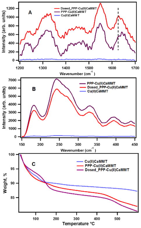
Samples of Cu(II)CaMMT, PPP-Cu(II)CaMMT and Dosed_PPP-Cu(II)CaMMT were characterized by Raman spectroscopy to determine the presence of the polymer, the sorption of phenol, and possible changes resulting from electron delocalization in the conjugated aromatic polymer system. The obtained results are presented in Fig. 1 (A and B).
Fig. 1.
Raman spectra and thermogravimetric analysis (TGA) data of PPP-Cu(II)CaMMT, DosedPPP-Cu(II)CaMMT and Cu(II)CaMMT showing (A) D and G bands between 1200 cm−1 – 1700 cm−1; (B) Stretching bands between 150 cm−1 – 400 cm−1; (C) TGA data collected at 10 °C/minute from 0 °C to 600 °C under nitrogen.
The results in Fig. 1A show characteristic observable changes in the different clay samples in the prominent Raman D, D′ and G band modes at 1342 cm−1, 1641 cm−1, and 1548 cm−1 for the clay composite samples (PPP-Cu(II)CaMMT and Dosed_PPP-Cu(II)CaMMT). These bands are characteristic of stretching vibrations of bonds between sp2-hybridized carbons typical for aromatic polymers, graphene, and carbon nanotubes.30–34 The in-plane bending vibrations of the methine C–H bonds are recognized as responsible for the shoulder peaks appearing at 1234 cm−1.31–32 These peaks were absent in the Cu(II)CaMMT, thus indicating the presence of PPP phase in the clay composite PPP-Cu(II)CaMMT.33 The 13 cm−1 shift in D′ band splitting from 1641 cm−1 to 1628 cm−1, observed in Figure 1A (marked by the dashed vertical line), is consistent with the electronic delocalization after exposure to phenol.31,34 Another distinguishable feature is the decreased Raman intensity in the stretching bands between 150 cm−1 and 400 cm−1 observed for Dosed_PPP-Cu(II)CaMMT (Fig. 1B). This further corroborates the prior evidence of aromatic ring interactions after phenol exposure and polymerization of PPP within the Cu(II)CaMMT system.34 Similar trends have been noted in single-walled carbon nanotube (SWCNT) systems for which reduction in Raman intensities within radial breathing mode band regions were correlated to the sorption of organic molecules on, or modification of, SWCNT surfaces.34, 35, 36
3.1.2. Thermogravimetric analysis (TGA)
TGA was used to determine the amount of PPP in the clay composite, with the results presented in Fig. 1C. Approximately 5% (0.101 mg) mass loss of the clay composite sample that occurred between 425 and 500 °C for both PPP-Cu(II)CaMMT and Dosed_PPP-Cu(II)CaMMT, was due to the loss of PPP.37–38 The TGA data also reveal three distinct weight loss patterns between 60 and 190 °C. For PPP-Cu(II)CaMMT there is a swift loss of mass until about 100 °C, which can be associated with the loss of water.39 For Cu(II)CaMMT the pattern is somewhat more complex, with a small shoulder between 60 and 120 °C, which can be attributed to water loss, including the surface-bound water.39 The majority of this surface water appears absent in PPP-Cu(II)CaMMT, which is consistent with the hydrophobicity of the PPP coating. The large shoulder apparent between 60 and 200 °C for Dosed_PPP-Cu(II)CaMMT can be attributed to the loss of the sorbed phenol due to vaporization.40
3.1.3. X-ray Diffraction (XRD)
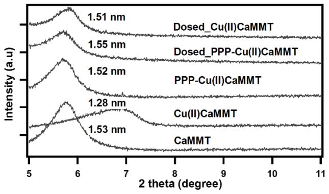
The XRD data presented in Fig. 2 show 1) a shift in the interlayer peak for CaMMT from 1.53 nm to 1.28 nm for Cu(II)CaMMT, as clear evidence of Cu(II) exchanging with interlayer cations (Ca2+, Mg2+ and Na+) in montmorillonite41, 2) a shift in the interlayer peak from 1.28 nm to 1.52 nm between Cu(II)CaMMT and PPP-Cu(II)CaMMT, serving as a clear evidence that the majority of the PPP polymer is formed in the interlayer, and 3) an increase in interlayer spacing after phenol dosing, which is indicative of phenol being sorbed into the interlayer space.
Fig. 2.
Powder XRD patterns showing the interlayer spacing for pre-phenol-exposed samples: CaMMT, Cu(II)CaMMT, PPP-Cu(II)CaMMT and post phenol-exposed samples: Dosed_PPP-Cu(II)CaMMT, and Dosed_Cu(II)CaMMT.
3.2 Formation and Characterization of EPFRs
3.2.1. Cu(II)CaMMT versus PPP-Cu(II)CaMMT
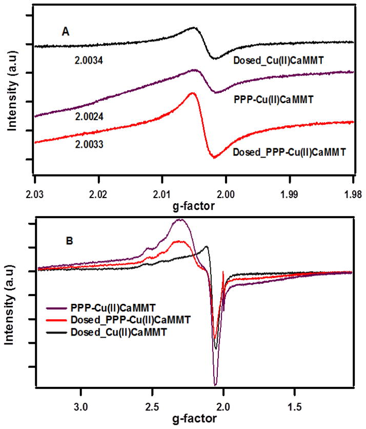
After exposure to phenol, EPFRs were formed by both Cu(II)CMMT and PPP-Cu(II)CaMMT, as evidenced by the EPR spectra in Fig. 3A, with g-factor values of 2.0034 and 2.0033 and peak to peak line widths, ΔHp-p, of ~5 and 7, respectively.
Fig. 3.
EPR Spectra of phenol exposed Cu-loaded clay (black), Cu-loaded-poly-p-phenylene clay, (purple), and phenol-exposed Cu-loaded clay-poly-p-phenylene (red) composite. Spectra were collected at (A) 150 G and (B) 6000 G magnetic fields.
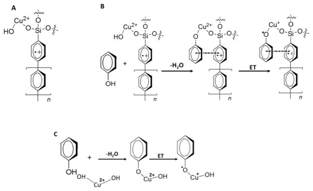
These values are consistent with phenoxyl-type radicals.6,8,42 When CaMMT was exposed to phenol, no radicals were formed, providing reasonable evidence that EPFRs formation in the studied systems involves both an organic precursor and an active transition metal (redox) centre. PPP-Cu(II)CaMMT inherently contains radicals—either intrinsically present (solitons), or resulting from PPP oxidation in air (polarons) (Scheme 1A).43 These radicals have a g-factor of 2.0024, indicating that the radical resonates mostly within the benzene rings of the conjugated PPP system and compares well with the g-factor of a free electron (2.0023) and PPP systems (2.0023 – 2.0025).44–46 A shift in g-factor from 2.0024 to 2.0033 was observed after phenol exposure, indicating a combination of carbon and oxygen-centred organic radical of phenoxyl type,42, 47–49 as well as a new source of radicals (as depicted in Scheme 1B). A new source of radicals is also supported by the g-factor of 2.0034 for the Dosed_Cu(II)CaMMT which, along with results from previous studies,42,44,47 demonstrates that, for copper-phenol systems with an adjacent oxygen atom, the radical mostly resides on the oxygen centres. Only slightly lower g-factor of 2.0033 for the Dosed_PPP-Cu(II)CaMMT strongly suggests the presence of a new but very similar radical to that present in the Dosed_Cu(II)CaMMT.
Scheme 1.
Proposed structures and mechanisms of EPFR formation in Cu-loaded clay and the PPP semiconducting polymer modified clay, showing possible π-π stacking interaction between polymer molecule and adsorbed phenol. The silyl group which can bind Cu(II) is an intrinsic part of the clay-confined PPP.
This new source of radicals also explains the fact that the same exposure to phenol leads to more radicals being formed in PPP-Cu(II)CaMMT (1.58 × 10¹⁷ spins/g, corrected to account for the radical inherent to PPP) compared to Cu(II)CaMMT (1.22 × 10¹⁷ spins/g).
Scheme 1B proposes a model for the formation of these radicals within the Dosed_PPP-Cu(II)CaMMT. The mechanisms put forward in Scheme 1 are supported by further EPR analysis at a magnetic field of 6000 G (cf. Fig. 3B). This analysis indicates a splitting of the hyperfine components (g|| = 2.345, g⊥ = 2.075), which are typical of paramagnetic Cu(II) ions.49–50 However, the distortion in shapes and positions of the hyperfine components at these regions after polymerization imply a mononuclear or binuclear copper-poly-p-phenylene complex formed on a fraction of Cu(II) paramagnetic centres.51–52 The required binding sites on PPP polymers are provided by the silyl groups which are used as anchoring units for clay immobilization of PPP polymer (see the Supporting Information for experimental details). These findings are consistent with the mechanisms illustrated in Scheme 1. The mechanism presented in Scheme 1(B and C) is also consistent with the formation of EPFRs through the chemisorption of an aromatic organic molecule to a transition metal centre and the subsequent reduction of the transition metal centre via the formation of a metal-oxygen complex.6,8, 16, 27
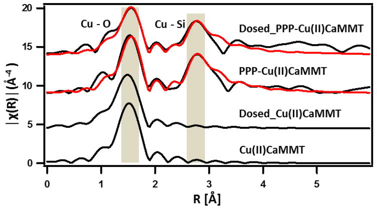
3.2.2. Extended X-Ray Absorption Fine Structure (EXAFS)
The EXAFS data shown in Fig. 4, represent the Fourier transform χ(R) (R space) of Cu(II)CaMMT, PPP-Cu(II)CaMMT, Dosed_Cu(II)CaMMT and Dosed_PPP-Cu(II)CaMMT, and further confirm the presence of a polymer unit bonded to Si in close proximity to the copper-oxygen bond, as hypothesized in Scheme 1A. The radial distances for the Cu-O and Cu-Si/Cu shells were clearly observed in PPP-Cu(II)CaMMT and Dosed_PPP-Cu(II)CaMMT. The peaks due to Cu-Si/Cu were absent in Cu(II)CaMMT and Dosed_Cu(II)CaMMT. This is supported strongly by fitting PPP-Cu(II)CaMMT and Dosed_PPP-Cu(II)CaMMT with a copper cyclohexasilicate crystal structural model, which best describes a Cu-O-Si structural backbone, as proposed in Scheme 1B. The first set of peaks represents Cu–O interatomic distances observed to be ~1.93 Å for Cu(II)CaMMT and Dosed_Cu(II)CaMMT and ~1.96 Å for PPP-Cu(II)CaMMT and Dosed_PPP-Cu(II)CaMMT (based on the fit to copper cyclohexasilicate crystal structure). According to the fit, the presence of Cu-Si coordination shell peak with a distance of ~3.17Å may suggest the presence of PPP polymer since it was anchored on the silica oxide. With the Cu–Cu distance of ~3.12 Å falling within the same range, a possible backscattering from the binuclear copper portion of the complex may also be possible by the presence of the polymer. This corroborates the previously presented Raman and EPR spectra, which indicate the presence of a copper-PPP complex.
Fig. 4.
Fourier transform of Cu K-edge K3-weighted EXAFS of Cu(II)CaMMT, Dosed_Cu(II)CaMMT, PPP-Cu(II)CaMMT Dosed_PPP-Cu(II)CaMMT. Black lines represent experimental data while red lines represent best fit to cyclohexasilicate crystal structure. Phase shift correction was not applied.
3.2.3. X-ray Absorption Near Edge Spectroscopy (XANES)
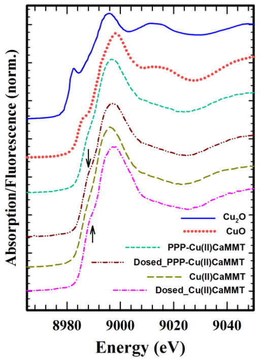
XANES experiments were also performed in order to investigate the changes in the oxidation state of copper in the EPFR forming process. Evidence of the redox process involved in the formation of EPFRs was observed at the 1s → 4p transition edge region of the Cu K-edge XANES spectra, as illustrated in Fig. 5. The result showed the appearance of a shoulder at ~8989.3 eV, as evidence of the absorption edge energy, after dosing for both Dosed_Cu(II)CaMMT and Dosed_PPP-Cu(II)CaMMT, a feature absent in the spectra for Cu(II)CaMMT and PPP-Cu(II)CaMMT, indicating Cu(II) to Cu(I) reduction, as previously reported in an EPFR forming process.53 Generally, Cu in +1 oxidation state is marked with prominent sharp peaks at the 1s → 4p transition region, as seen in Cu2O, while shifts to lower and higher energies in this region have been reported to indicate reduction and oxidation of Cu species, respectively.54
Fig. 5.
Cu K-edge XANES spectra of Cu(II)CaMMT, Dosed_Cu(II)CaMMT, PPP-Cu(II)CaMMT, Dosed_PPP-Cu(II)CaMMT, and standards Cu2O and CuO.
3.3 EPFR Lifetimes
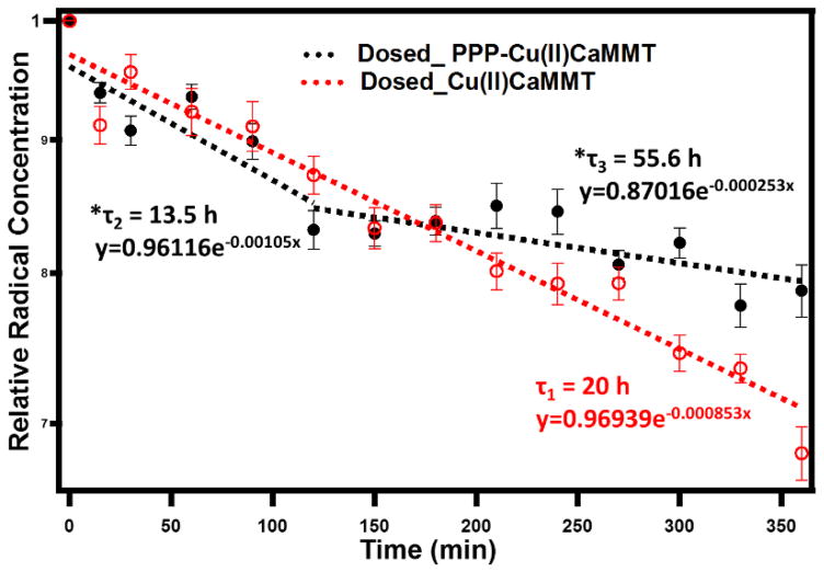
In order to gain insight into the decay kinetics of EPFRs present in Dosed_Cu(II)CaMMT and Dosed_PPP-Cu(II)CaMMT, time dependent open air exposure studies were carried out, and the results are presented in Fig. 6. The data in Fig. 6. were used to calculate the lifetimes (τ) according to the pseudo-first-order integrated rate law expression: In(R/R0) = −kt, where tτ = 1/k and k and e represent the slope of the regression and the base of the natural logarithm, respectively.8
Fig. 6.
Lifetimes of phenoxyl radical (EPFR) formed under 30 minutes thermal pre-heating at 40 °C in ambient air with 5 min gas phase phenol exposure to Cu(II)CaMMT (open red circles and dashed red fit line) and PPP-Cu(II)CaMMT (closed black circles and dashed black fit lines). Igor Pro 6.37 was used for all line fitting. * Corrected lifetime utilizing a 0.843 PPP decay factor [to account for the decay of the radicals associated with PPP]).
3.3.1. Dosed_Cu(II)CaMMT
A decay lifetime of ~20 h (τ1 = ~20 h) was found for the Dosed_Cu(II)CaMMT-associated EPFRs, as shown with the pseudo-first-order rate law expression fit line (red) in Fig. 6. A shorter decay lifetime has been found for EPFRs formed on silica-supported Cu(II)O (τ1 = ~74 min).16 The ~1.5 orders slower decay of the Dosed_Cu(II)CaMMT EPFRs can be attributed to the confined environment of the adsorbed (physisorbed and chemisorbed) phenol to the Cu(II) metal centre.8 Due to the layered structure of montmorillonite clay, phenoxyl radicals can be formed through binding of phenol with cation-exchanged copper in the interlayer (as well as edges) of the clay, resulting in the entrapment of radicals within the clay matrix (internal radicals).47, 55–56
The XRD data (cf. Fig. 2) strongly support this assertion, with a significant shift in the interlayer peak spacing for Cu(II)CaMMT from 1.28 nm to 1.51 nm after phenol exposure (Dosed_ Cu(II)CaMMT). This presents an additional barrier to the decomposition of the EPFRs formed in the clay, making them more stable than the EPFRs formed on silica-supported Cu(II)O.16
3.3.2. Dosed_PPP-Cu(II)CaMMT
The EPFRs associated with the Dosed_PPP-Cu(II)CaMMT yielded two decay lifetimes of ~13.5 h and 55.6 h (τ2 and τ3), as shown with the pseudo-first-order rate law expression fit lines (black) in Fig. 6, after accounting for the PPP radical decay. The two decay periods occurred: from the initial air exposure (0 min) to 180 min and from 180 to 360 min. The g-factor and ΔHp-p values varied between 2.0030 and 2.0034 and between 6.0 and 7.2, respectively, and are consistent with previously reported results of the decay of phenoxyl-type oxygen-centred EPFRs.8,42,47 In addition, EPFRs formed in real soil samples contaminated with pentachlorophenol (PCP) have shown similar multiple decays.18
These two decays can be assigned to 1) the faster decaying EPFRs chemisorbed to Cu(II) metal centres, as in the case of Dosed_Cu(II)CaMMT (Scheme 1C) and 2) the slower decaying Cu(II)-bound PPP polymer chain-associated EFPRs with a possible electron shuttling taking place between the phenol and the PPP polymer chain, utilizing the conjugated backbone system.
Scheme 2.
Proposed •OH radical generation routes involving redox-active conjugated polymer (PPP) and EPFRs in the presence of molecular oxygen.13
The XRD data presented in Fig. 2 show interlayer peak positions of 1.52 and 1.55 nm for PPP-Cu(II)CaMMT and Dosed_PPP-Cu(II)CaMMT, respectively, indicating the presence of the PPP and the subsequent phenol intercalation after dosing. These patterns are similar to those exhibited by Dosed_Cu(II)CaMMT, and serve as strong evidence of phenol being adsorbed between clay layers, as illustrated in Scheme 1B. It can be speculated that the larger interlayer spacing in Dosed_PPP-Cu(II)CaMMT compared to Dosed_Cu(II)CaMMT allows for an easier oxygen access, and hence, shorter decay lifetimes of the Cu(II)-chemisorbed EPFRs in Dosed_PPP-Cu(II)CaMMT (~13.5 h versus ~20h).
While the second mechanism is not fully understood, previous works have proposed that aromatic ring stacking between the polymer and phenol allows for π-π interactions resulting in the formation of sandwich dimers,27,57 as illustrated in Scheme 1B. These dimers would stabilize the formed EPFRs by delocalizing the unpaired electron over the polymer’s extended conjugated π system. This is consistent with the longer EPFR lifetime associated with the Dosed_PPP-Cu(II)CaMMT. Also, PPP could be envisioned to assume a “flapping” orientation within the clay matrix, resulting in a π-cation interaction,57–58 thus increasing the chances of the sorption of phenol onto the polymer. This is equivalent to the interaction that leads to the formation of stable copper-quinone complexes,59 as may be found in the real soil system, where quinone moieties act as the main electron shuttling agents.60–61 With the sorption of phenol onto the PPP chain, electron shuttling possibilities cannot be disregarded.
In regards to the exact EPFR decay mechanism, a potential pathway would be a pseudo-first order interaction between the radical with oxygen, as has been previously proposed.18 Surface reaction models, such as Langmuir–Hinshelwood and Eley–Rideal, have also been suggested as possible routes by which EPFRs form and decompose to yield dioxins or other products of radical recombination.18,62
3.4. Detection of Hydroxyl Radicals by EPR-Spin Trapping
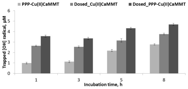
EPFRs have been shown to initiate the generation of superoxide and hydroxyl radicals through the reduction of oxygen. In order to investigate hydroxyl radical (•OH) generation, EPR spin trapping experiments were carried out using 5,5-dimethyl-1-pyrroline-N-oxide (DMPO). The concentration of DMPO-OH adduct was estimated from the double integration of the DMPO-OH characteristic 1:2:2:1 EPR peak signals with hyperfine splitting of aN = 15.066 G, aH = 14.735 G (Fig. S1), which is the chemical signature of the trapped •OH. In the present study, Cu(II)CaMMT was combined with molecular oxygen and used as a reference for •OH generation. The results for the •OH generated by this none EPFR containing system were subtracted from those obtained for •OH generated by PPP-Cu(II)CaMMT (no EPFRs), Dosed_Cu(II)CaMMT, and Dosed_PPP-Cu(II)CaMMT systems and are presented in Fig. 7 for incubation times of 1, 3, 5, and 8 h.
Fig. 7.
Chart derived from the EPR spectra of spin trapped [OH] for PPP-Cu(II)CaMMT, Dosed_Cu(II)CaMMT, and Dosed_PPP-Cu(II)CaMMT. All Samples were incubated in buffer (PBS pH 7.4) suspension with DMPO.
The data presented in Fig. 7 provide two very clear general trends: (i) the EPFR-containing particles (dosed systems) yield significantly more •OH radicals than the non-EPFR containing systems, and (ii) there is an increase in the trapped •OH radical with increasing time.
In addition to the redox cycling route involving the reduction of molecular oxygen into superoxide radical ion, which generates hydrogen peroxide and hydroxyl radical through disproportionation and Fenton chemistry (Scheme 2), other EPFR decay routes can also result in the production •OH for the systems under study. For example, nucleophilic addition of water is often considered as artefactual to •OH generation.12, 63 To account for these possibilities, the undosed Cu(II)CaMMT was used. Likewise, the undosed PPP-(Cu(II)CaMMT was used as an additional control to account for the radicals inherently present in the PPP-Cu(II)CaMMT conjugated polymer-based systems. After the first hour of incubation, due to the presence of EPFRs, Dosed_PPP-Cu(II)CaMMT were shown to generate 72% more •OH compared to the PPP-Cu(II)CaMMT. This number represents 98% of the •OH generated by the Dosed_Cu(II)CaMMT, after the •OH radicals generated by the PPP in the system are accounted for. Similar results have been previously reported with a 50% increase in the number of •OH radicals generated between a tarball-associated EPFRs compared to the non-EPFR particle systems.27 However, as noted, a fraction of the •OH generated by this system can be attributed to the radicals within the PPP-Cu(II)CaMMT conjugated polymer system being active in •OH generation. This implies that conjugated polymer PPP catalyzes the generation of •OH in a similar fashion to how EPFR-containing systems do, due to the π-electron conjugated chain ability to donate electrons via the formation of cation radical (polaron)43 as seen in Scheme 2. This means that conjugated polymer can facilitate reduction of molecular oxygen to superoxides. Analogously, •OH can be generated through quinone-quinoid redox cycling, as demonstrated with quinone moieties inherent in SOM. This may help explain the ability of natural organic matter (NOM) to induce the formation of ROS in biological entities.64–66
Also, this is in agreement with the explanation that a range of aromatic functionalities, such as graphene oxide and biochars, catalyze the formation of •OH through the activation of molecular O2 to produce superoxide radical (•O2−).67–68 The superoxide radical produced in this process may further act as an oxidant, initiating a Fenton-type reaction that ultimately results in •OH generation.13,63
4.0 Conclusions
Fundamental: Our results demonstrate that a simple copper-exchanged montmorillonite clay system (Cu(II)CaMMT) and an electron shuttling organic polymer-modified clay system (PPP-Cu(II)CaMMT) can yield EPFRs when exposed to phenol under environmentally relevant conditions. This finding illustrates that EPFRs may be formed on just the Cu-containing clay components of soils and provides evidence that soil organic matter (SOM) may act as an electron shuttle between mineral/clay redox centres and pollutants, aiding in the formation of EPFRs as well as stabilizing the formed radicals. Our results provide insights into the role of soil component in the formation of EPFRs at Superfund sites and that even with the minimum quantity of SOM (e.g., 5% polymer) in the soil, the radical can persist longer due to aromatic stabilization. The type of organic radicals and the different decay patterns, as those observed for the Dosed_PPP-Cu(II)CaMMT system, are akin to those observed in PCP-contaminated soils, biochar, and tarballs, all of which are identical in composition in terms of the presence of aromatic moieties as well as metal redox centres. While the complex nature of these materials makes mechanistic studies into radical formation very difficult, this work demonstrates how such studies can be facilitated by the use of properly designed model systems.
Health and Remediation: From a health perspective, the real concern is that, in windy conditions, EPFR-contaminated soil can turn into airborne dust particulate matter, especially during periods of low precipitation, and subsequently become inhaled or ingested by humans. Since EPFRs are known to induce oxidative stress through the formation of reactive oxygen species, they can lead to cardiopulmonary diseases and cancer.13–14 The results for the Dosed_PPP-Cu(II)CaMMT system indicate that soil remediation methods must be developed, in which the native SOM is penetrated in order to destroy the EPFRs present.
The approach put forward in this work allows one to systematically study and understand the underlying mechanisms of EPFR formation in single and bi-component surrogate soil models. However, when applying the findings from this study to real world soils, caution must be exercised as the role of a number of other important soil components, such as biological enzymes (e.g., laccase), and various environmental conditions have not been accounted for. Nevertheless, the results from this study will benefit future efforts that take these additional variables into account.
Acknowledgments
Support for this research was provided by the NIEHS Superfund Research Program through grant, 2P42ES013648-03, as well as the National Science Foundation via grant CHE-1411547. In addition, preparation of conjugated polymer-clay composites was funded by the National Science Foundation (grant DMR-1006336). We also thank Mr. Christopher O’Loughlin of LSU, Electronic Material and Device Laboratory in the Department of Electrical and Computer Engineering for his assistance with the Raman measurements.
Notes and references
- 1.Doick KJ, Klingelmann E, Burauel P, Jones KC, Semple KT. Environmental Science & Technology. 2005;39:3663–3670. doi: 10.1021/es048181i. [DOI] [PubMed] [Google Scholar]
- 2.Moeckel C, Nizzetto L, Guardo AD, Steinnes E, Freppaz M, Filippa G, Camporini P, Benner J, Jones KC. Environmental Science & Technology. 2008;42:8374–8380. doi: 10.1021/es801703k. [DOI] [PubMed] [Google Scholar]
- 3.dela Cruz ALN, Gehling W, Lomnicki S, Cook R, Dellinger B. Environmental Science & Technology. 2011;45:6356–6365. doi: 10.1021/es2012947. [DOI] [PMC free article] [PubMed] [Google Scholar]
- 4.dela Cruz ALN, Cook RL, Dellinger B, Lomnicki SM, Donnelly KC, Kelley MA, Cosgriff D. Environmental Science: Processes & Impacts. 2014;16:44–52. doi: 10.1039/c3em00428g. [DOI] [PMC free article] [PubMed] [Google Scholar]
- 5.Dellinger B, Lomnicki S, Khachatryan L, Maskos Z, Hall RW, Adounkpe J, McFerrin C, Truong H. Proceedings of the Combustion Institute. 2007;31:521–528. doi: 10.1016/j.proci.2006.07.172. [DOI] [PMC free article] [PubMed] [Google Scholar]
- 6.Vejerano E, Lomnicki S, Dellinger B. Environmental Science & Technology. 2010;45:589–594. doi: 10.1021/es102841s. [DOI] [PubMed] [Google Scholar]
- 7.Truong H, Lomnicki S, Dellinger B. Chemosphere. 2008;71:107–113. doi: 10.1016/j.chemosphere.2007.10.007. [DOI] [PubMed] [Google Scholar]
- 8.Nwosu UG, Roy A, dela Cruz ALN, Dellinger B, Cook R. Environmental Science: Processes & Impacts. 2016;18:42–50. doi: 10.1039/c5em00554j. [DOI] [PMC free article] [PubMed] [Google Scholar]
- 9.Truong H, Lomnicki S, Dellinger B. Environmental Science & Technology. 2010;44:1933–1939. doi: 10.1021/es902648t. [DOI] [PMC free article] [PubMed] [Google Scholar]
- 10.Kunisue T, Nakanishi S, Oka N, Sato F, Tsurumi M, Tanabe S. Environmental Science & Technology. 2006;40:6919–6927. doi: 10.1021/es061153a. [DOI] [PubMed] [Google Scholar]
- 11.Holt E, Weber R, Stevenson G, Gaus C. Environmental Science & Technology. 2010;44:5409–5415. doi: 10.1021/es903915k. [DOI] [PubMed] [Google Scholar]
- 12.Ferré-Huguet N, Nadal M, Schuhmacher M, Domingo JL. Environmental Science & Technology. 2006;40:61–66. doi: 10.1021/es051630+. [DOI] [PubMed] [Google Scholar]
- 13.Khachatryan L, Vejerano E, Lomnicki S, Dellinger B. Environmental Science & Technology. 2011;45:8559–8566. doi: 10.1021/es201309c. [DOI] [PMC free article] [PubMed] [Google Scholar]
- 14.Dellinger B, Pryor WA, Cueto R, Squadrito GL, Hegde V, Deutsch WA. Chemical Research in Toxicology. 2001;14:1371–1377. doi: 10.1021/tx010050x. [DOI] [PubMed] [Google Scholar]
- 15.Kelley MA, Hebert VY, Thibeaux TM, Orchard MA, Hasan F, Cormier SA, Thevenot PT, Lomnicki SM, Varner KJ, Dellinger B, Latimer BM, Dugas TR. Chemical Research in Toxicology. 2013;26:1862–1871. doi: 10.1021/tx400227s. [DOI] [PMC free article] [PubMed] [Google Scholar]
- 16.Lomnicki S, Truong H, Vejerano E, Dellinger B. Environmental Science & Technology. 2008;42:4982–4988. doi: 10.1021/es071708h. [DOI] [PubMed] [Google Scholar]
- 17.Li H, Pan B, Liao S, Zhang D, Xing B. Environmental Pollution. 2014;188:153–158. doi: 10.1016/j.envpol.2014.02.012. [DOI] [PubMed] [Google Scholar]
- 18.Nd Cruz AL, Cook RL, Lomnicki SM, Dellinger B. Environmental Science & Technology. 2012;46:5971–5978. doi: 10.1021/es300362k. [DOI] [PMC free article] [PubMed] [Google Scholar]
- 19.Guillén F, Martínez MJ, Gutiérrez A, Del Rio J. International Microbiology: the Official Journal of the Spanish Society for Microbiology. 2005;8 187204Minami. [PubMed] [Google Scholar]
- 20.Hall SJ, Silver WL. Global Change Biology. 2013;19:2804–2813. doi: 10.1111/gcb.12229. [DOI] [PubMed] [Google Scholar]
- 21.Schulten H-R. Fresenius’ Journal of Analytical Chemistry. 351:62–73. [Google Scholar]
- 22.Kappler A, Benz M, Schink B, Brune A. FEMS Microbiology Ecology. 2004;47:85–92. doi: 10.1016/S0168-6496(03)00245-9. [DOI] [PubMed] [Google Scholar]
- 23.Piepenbrock A, Schröder C, Kappler A. Environmental Science & Technology. 2014;48:1656–1664. doi: 10.1021/es404497h. [DOI] [PubMed] [Google Scholar]
- 24.Gu C, Liu C, Ding Y, Li H, Teppen BJ, Johnston CT, Boyd SA. Environmental Science & Technology. 2011;45:3445–3451. doi: 10.1021/es104225d. [DOI] [PubMed] [Google Scholar]
- 25.Gu C, Liu C, Johnston CT, Teppen BJ, Li H, Boyd SA. Environmental Science & Technology. 2011;45:1399–1406. doi: 10.1021/es103324z. [DOI] [PMC free article] [PubMed] [Google Scholar]
- 26.Gu C, Li H, Teppen BJ, Boyd SA. Environmental Science & Technology. 2008;42:4758–4763. doi: 10.1021/es7029834. [DOI] [PubMed] [Google Scholar]
- 27.Kiruri LW, Dellinger B, Lomnicki S. Environmental Science & Technology. 2013;47:4220–4226. doi: 10.1021/es305157w. [DOI] [PMC free article] [PubMed] [Google Scholar]
- 28.Ravel B, Newville M. Journal of Synchrotron Radiation. 2005;12:537–541. doi: 10.1107/S0909049505012719. [DOI] [PubMed] [Google Scholar]
- 29.Breuer K-H, Eysel W, Müller R. Zeitschrift für Kristallographie. 1989;187:15–23. [Google Scholar]
- 30.Cervantes TNM, Bento DC, Maia ECR, Zaia DAM, Laureto E, Silva MAT, Moore GJ, Santana H. Journal of Materials Science: Materials in Electronics. 2012;23:1916–1921. [Google Scholar]
- 31.Wang Z, Rothberg LJ. ACS Nano. 2007;1:299–306. doi: 10.1021/nn700213t. [DOI] [PubMed] [Google Scholar]
- 32.Rao S, Bálint Š, Cossins B, Guallar V, Petrov D. Biophysical Journal. 96:209–216. doi: 10.1529/biophysj.108.139097. [DOI] [PMC free article] [PubMed] [Google Scholar]
- 33.Wu J, Gherghel L, Watson MD, Li J, Wang Z, Simpson CD, Kolb U, Müllen K. Macromolecules. 2003;36:7082–7089. [Google Scholar]
- 34.Takenobu T, Takano T, Shiraishi M, Murakami Y, Ata M, Kataura H, Achiba Y, Iwasa Y. Nature Materials. 2003;2:683–688. doi: 10.1038/nmat976. [DOI] [PubMed] [Google Scholar]
- 35.Lefrant S, Baibarac M, Baltog I, Mevellec JY, Godon C, Chauvet O. Diamond and Related Materials. 2005;14:867–872. [Google Scholar]
- 36.Hupp JT, Williams RD. Accounts of Chemical Research. 2001;34:808–817. doi: 10.1021/ar9602720. [DOI] [PubMed] [Google Scholar]
- 37.Ahn T, Jang MS, Shim H-K, Hwang D-H, Zyung T. Macromolecules. 1999;32:3279–3285. [Google Scholar]
- 38.Stack S, O’Donoghue O, Birkinshaw C. Polymer Degradation and Stability. 2003;79:29–36. [Google Scholar]
- 39.Elkhalifah AEI, Murugesan T, Bustam MA. 2011 [Google Scholar]
- 40.Zhou J, Yao Z, Chen Y, Wei D, Wu Y, Xu T. Polymer Composites. 2013;34:1245–1249. [Google Scholar]
- 41.Seger MR, Maciel GE. Environmental Science & Technology. 2006;40:797–802. doi: 10.1021/es051704h. [DOI] [PubMed] [Google Scholar]
- 42.Kiruri LW, Khachatryan L, Dellinger B, Lomnicki S. Environmental Science & Technology. 2014;48:2212–2217. doi: 10.1021/es404013g. [DOI] [PMC free article] [PubMed] [Google Scholar]
- 43.Bredas JL, Street GB. Accounts of Chemical Research. 1985;18:309–315. [Google Scholar]
- 44.Tian L, Koshland CP, Yano J, Yachandra VK, Yu ITS, Lee SC, Lucas D. Energy & Fuels. 2009;23:2523–2526. doi: 10.1021/ef8010096. [DOI] [PMC free article] [PubMed] [Google Scholar]
- 45.List EJW, Partee J, Shinar J, Scherf U, Müllen K, Zojer E, Petritsch K, Leising G, Graupner W. Physical Review B. 2000;61:10807–10814. [Google Scholar]
- 46.Dyakonov V, Zoriniants G, Scharber M, Brabec CJ, Janssen RAJ, Hummelen JC, Sariciftci NS. Physical Review B. 1999;59:8019–8025. [Google Scholar]
- 47.Gehling W, Dellinger B. Environmental Science & Technology. 2013;47:8172–8178. doi: 10.1021/es401767m. [DOI] [PMC free article] [PubMed] [Google Scholar]
- 48.Liao S, Pan B, Li H, Zhang D, Xing B. Environmental Science & Technology. 2014;48:8581–8587. doi: 10.1021/es404250a. [DOI] [PubMed] [Google Scholar]
- 49.Calvo R, Passeggi MC, Isaacson RA, Okamura MY, Feher G. Biophysical Journal. 1990;58:149–165. doi: 10.1016/S0006-3495(90)82361-4. [DOI] [PMC free article] [PubMed] [Google Scholar]
- 50.Contel M, Villuendas PR, Fernández-Gallardo J, Alonso PJ, Vincent J-M, Fish RH. Inorganic Chemistry. 2005;44:9771–9778. doi: 10.1021/ic051220m. [DOI] [PubMed] [Google Scholar]
- 51.Alves WA, Almeida-Filho SAd, Santos RHdA, Paduan-Filho A, Ferreira AMdC. Journal of the Brazilian Chemical Society. 2004;15:872–883. [Google Scholar]
- 52.Pavlova SV, To HL, Chan ESH, Li H-W, Mak TCW, Lee HK, Chan SI. Dalton Transactions. 2006:2232–2243. doi: 10.1039/b513898a. [DOI] [PubMed] [Google Scholar]
- 53.Alderman SL, Farquar GR, Poliakoff ED, Dellinger B. Environmental Science & Technology. 2005;39:7396–7401. doi: 10.1021/es050063n. [DOI] [PubMed] [Google Scholar]
- 54.Dubale AA, Pan C-J, Tamirat AG, Chen H-M, Su W-N, Chen C-H, Rick J, Ayele DW, Aragaw BA, Lee J-F, Yang Y-W, Hwang B-J. Journal of Materials Chemistry A. 2015;3:12482–12499. [Google Scholar]
- 55.Okada T, Watanabea Y, Ogawa M. Chemical Communications. 2004:320–321. doi: 10.1039/b312962d. [DOI] [PubMed] [Google Scholar]
- 56.Wang Q, Peng L, Li G, Zhang P, Li D, Huang F, Wei Q. International Journal of Molecular Sciences. 2013;14:12520. doi: 10.3390/ijms140612520. [DOI] [PMC free article] [PubMed] [Google Scholar]
- 57.Wheeler SE. Journal of the American Chemical Society. 2011;133:10262–10274. doi: 10.1021/ja202932e. [DOI] [PubMed] [Google Scholar]
- 58.Keiluweit M, Kleber M. Environmental Science & Technology. 2009;43:3421–3429. doi: 10.1021/es8033044. [DOI] [PubMed] [Google Scholar]
- 59.Roy S, Sarkar B, Bubrin D, Niemeyer M, Záliš S, Lahiri GK, Kaim W. Journal of the American Chemical Society. 2008;130:15230–15231. doi: 10.1021/ja804429v. [DOI] [PubMed] [Google Scholar]
- 60.Scott DT, McKnight DM, Blunt-Harris EL, Kolesar SE, Lovley DR. Environmental Science & Technology. 1998;32:2984–2989. [Google Scholar]
- 61.Nevin KP, Lovley DR. Environmental Science & Technology. 2000;34:2472–2478. [Google Scholar]
- 62.Boyd SA, Mortland MM. Nature. 1985;316:532–535. [Google Scholar]
- 63.Burkitt MJ, Ying Tsang S, Ching Tam S, Bremner I. Archives of Biochemistry and Biophysics. 1995;323:63–70. doi: 10.1006/abbi.1995.0010. [DOI] [PubMed] [Google Scholar]
- 64.Hseu Y-C, Senthil Kumar KJ, Chen C-S, Cho H-J, Lin S-W, Shen P-C, Lin C-W, Lu F-J, Yang H-L. Toxicology and Applied Pharmacology. 2014;274:249–262. doi: 10.1016/j.taap.2013.11.002. [DOI] [PubMed] [Google Scholar]
- 65.Qi S, Md Hartog GJ, Bast A. Environmental Toxicology and Pharmacology. 2008;26:96–101. doi: 10.1016/j.etap.2008.02.007. [DOI] [PubMed] [Google Scholar]
- 66.Schepetkin IA, Khlebnikov AI, Ah SY, Woo SB, Jeong C-S, Klubachuk ON, Kwon BS. Journal of Agricultural and Food Chemistry. 2003;51:5245–5254. doi: 10.1021/jf021101e. [DOI] [PubMed] [Google Scholar]
- 67.Fang G, Gao J, Liu C, Dionysiou DD, Wang Y, Zhou D. Environmental Science & Technology. 2014;48:1902–1910. doi: 10.1021/es4048126. [DOI] [PubMed] [Google Scholar]
- 68.Su C, Acik M, Takai K, Lu J, Hao S-j, Zheng Y, Wu P, Bao Q, Enoki T, Chabal YJ, Ping Loh K. Nature Communications. 2012;3:1298. doi: 10.1038/ncomms2315. [DOI] [PubMed] [Google Scholar]


