

Abstract
We examine the process of expansion of a focal adhesion complex by which a biological membrane containing mobile binders adheres to a substrate with complementary binders. Attention is focused on the situation, common among living cells, in which the mean mobile binder density is insufficient to overcome generic resistance to close approach of the membrane to its substrate. For the membrane to adhere, binders must be recruited from adjacent regions to join an adhesion patch of density adequate for adhesion, thereby expanding the size of the patch. The specific configuration examined is the expansion of a circular adhesion zone for which diffusive binder transport driven by a chemical potential gradient is the mechanism of binder recruitment. An aspect of the process of particular interest is the stability of the circular shape of the expanding front. It is found that the adhesion front radius increases as √t, where t is the time elapsed since nucleation, and that the circular shape becomes unstable under sinusoidal perturbations for radii large compared with the nucleation size, as observed in recent experiments.
Keywords: adhesion receptors, biomembrane, cell adhesion
Adhesion of cells with other cells and surfaces plays an important role in processes such as cell migration, spreading, differentiation, and growth. The interactions that are responsible for cell adhesion include nonspecific electrostatic and repulsive steric forces as well as specific binding between receptors and ligands. In a series of early and important papers, Bell and coworkers (1–3) have developed quantitative models for cell adhesion based on equilibrium thermodynamics; their work shows that adhesion of cells involves a competition between the nonspecific repulsive forces due to the presence of glycocalyx and the specific bonding interactions between ligand–receptor pairs. The changes in shapes of adhered cells due to the deformation of the cell membrane and the role of ligand–receptor bond kinetics on attachment and separation of cells has been considered by Evans (4, 5) and Dembo and coworkers (6). Advances in experimental techniques based on atomic force microscopes, optical tweezers, and flexible transducers has led to considerable improvement in the understanding of ligand–receptor interactions that are responsible for cell adhesion (7–9).
Recent experiments have shown that cell adhesion to surfaces which carry a large concentration of receptors that are complementary to the binders in the cell membrane results in the formation of localized regions of tight adhesion (sometimes referred to as focal adhesion complexes). Examples include spreading of blood platelets (10), vesicles (11, 12), and different types of cells including fibroblasts, melanocytes, osteoblasts, lymphoblasts, and red blood cells (13–16) on substrates functionalized with receptors. On the basis of experiments on adhesion of a variety of cultured cells on arrays of patterned gold nanodots with a single bound integrin per dot, Arnold and coworkers (16) have proposed that the center-to-center spacing between integrin–receptor bonds should generally be smaller than ≈60 nm for the formation of focal adhesion complexes. Since this areal density far exceeds the mean density of mobile binders on the surfaces of cells, they have to arrive at the adhesion complexes via diffusion from the nonadhering parts of the cell wall. The adhesion process can therefore be viewed as a lateral phase segregation or first-order wetting process (17, 18) that involves nucleation and growth of areas with large binder density.
Much progress has been made in the past few years in quantitative measurement of the dynamics and kinetics of adhesion mediated by mobile binders. In particular, Sackmann and coworkers (11, 12) have used optical imaging techniques to obtain the growth rate and shapes of advancing fronts of adhesion complexes formed by giant vesicles on integrin-coated glass substrates. The kinetics of adhesion was studied as a function of the concentration of mobile hexapeptides carrying the Arg-Gly-Asp (RGD) motif on the vesicle surfaces; these lipids are selectively recognized by the integrin of blood platelets on the glass substrates. (A more common configuration in animal cells is that the membrane contains mobile integrins while the complementary receptors are attached to the substrate.) When the areal density of the RGD lipids is smaller than that of the active physisorbed integrin molecules on the substrate, they find that the radius of the approximately circular adhesion patch increases with time from nucleation as √t, whereas larger lipid concentrations show a growth behavior that is linear in time. Furthermore, the growth front was found to exhibit alternating convex and concave regions in the square-root regime of motion but was relatively smooth in the linear regime, indicating the presence of growth instabilities of the front the former case. A similar transition from the square-root to linear growth regime has been observed during the spreading of red blood cells on protein-decorated substrates (15). A square-root spreading rate has also been reported in the case of blood platelets on protein-coated glass plates (10). Although theoretical models (11, 19, 20), based on the growth of one-dimensional adhesion fronts, have obtained a √t growth law in the binder-diffusion limited kinetic regime, the stability of the advancing front has not been studied. Also, these models do not discuss the range of ligand and receptor concentrations where the square-root law remains valid.
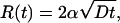
In this article, we consider the growth of a circular adhesion front that advances by recruiting binders from the nonadhered part of the cell through surface diffusion. The terms “receptor” and “ligand” are not precise, and, in this discussion, both the mobile ligands in the membrane and their receptors fixed in the substrate are referred to simply as binders. We show that the radius of the front follows the growth law R(t) = 2α√Dt, where D is the diffusion coefficient of the binders confined to the membrane, and α is a coefficient that depends on the ratio of the concentration of the ligands on the cell wall to the concentration of receptors on the substrate. We find that parameter α is finite when this ratio is less than unity but diverges as it approaches unity, signaling the breakdown of the square-root growth regime. This result explains the cross-over observed in ref. 11 when the surface densities of the ligands equals the receptor density on the glass substrate. Furthermore, we find that the advancing front is unstable to perturbations in its shape: Small convex (concave) shape modulations of the front lead to an increase (decrease) in the diffusion mediated binder flux in its vicinity, resulting in further growth of the perturbation and roughening of the front. We show that the shape of the advancing front is determined by a competition between the tendency of the diffusion flux to roughen the front and the energy cost involved in increasing its perimeter. Using a linear instability analysis, the number of concave/convex regions in the advancing front is found to scale with the radius R of the adhesion zone as (R/Rc)1/2, where Rc is the critical radius for nucleation. When R = 8 μm and Rc = 200 nm (11), the number of crests and troughs in the front is ≈8, in good agreement with the observations in ref. 11. We also note that since binder diffusion is not involved in the linear growth regime, the above instability is absent and the front motion should be smooth as seen in the experiments (11).
Evolution of an Advancing Circular Adhesion Front
In this section, we propose the mechanism of advance of an adhesion front and identify the energetic forces that influence its advance. Before adhesion, the distribution of binders in the cell membrane is spatially uniform, consistent with the requirement of maximum entropy, with a number density c∞ per unit area. Whereas this distribution is uniform statistically, the actual distribution is far from uniform. The binders continually undergo random migration due to thermal agitation, giving rise to small regions of the membrane with binder densities much higher or lower than the mean density. The dense clusters provide likely nucleation sites for adhesion zones if they form while the membrane is in close proximity to a complementary substrate. According to classical nucleation theory, a minimum cluster size is required to carry the system beyond a nucleation activation barrier, and this minimum size comes into play in the present discussion.
The driving force for formation and growth of an adhesion complex is the reduction in an internal energy that is achieved upon completion of molecular bonds (see the schematic in Fig. 1). The magnitude of this energy per bond is denoted by CbkBT, where kB is the Boltzmann constant, T is absolute temperature, and Cb is a number commonly in the range 5 < Cb < 35. As noted above, it has been demonstrated experimentally that a certain density of bonds is essential for adhesion. Here, the number of bonds per unit area within the adhesion zone is presumed to be uniform with a value c0. The value of this density is essentially determined by the surface density of binding sites on the substrate, which, for the experiments reported in ref. 11, was fixed at the outset.
Fig. 1.

Schematic diagram of the edge region of radius R(t) of the adhesion zone. (Upper) The transition from the free portion of the membrane to the bound portion is shown to have a narrow but finite width Λ; this transition is assumed to occur across a line in the overall model of the process. The thickness of the glycocalyx is denoted by Δ. (Lower) Sketch of the radial distribution of binder density c(r, t) at a fixed time, showing the density c0 within the adhesion zone, the edge density c+, and the initial uniform density c∞.
Work must be expended in several ways to effect adhesion. A cell membrane is normally protected against casual adhesions by the glycocalyx. This is a polymeric surface coat extending outward some tens of nanometers from the surface of the membrane. Some work must be expended in compressing the glycocalyx layer enough to permit binder–receptor linkages, or perhaps in inducing the polymer strands to migrate laterally away from the adhesion zone. The resistance is represented generically by a potential energy of the membrane that increases as it approaches its substrate. This adhesion-resisting potential energy per unit area is denoted by G(z)kBT, where z is the normal distance of separation of the membrane surface from its substrate, with z = 0 being the adhered configuration. G(0) = G0 is usually believed to be in the range 0.1 nm-2 < G0 < 10 nm-2, and the effective spatial range of this potential is the thickness of the glycocalyx, say Δ. In general, understanding of this deformation resistance is rudimentary at best.
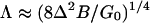
In general, the membrane shape does not conform naturally to the shape of the substrate to which it adheres. Consequently, the membrane must be deformed elastically to enforce this conformation. Such deformation occurs predominantly by bending, and the elastic bending modulus is denoted by BkBT. The number B is commonly found to be in the range 10 < B < 30. Bending effects are believed to be most pronounced near the edge of the adhesion zone, which is where the membrane must make the transition from being free to the fully adhered state as it is forced through the resisting glycocalyx. If G(z) decreases linearly with distance z from G(0) = G0 to G(Δ) = 0, then the width of the transition region can be estimated to be
 |
[1] |
on the basis of elementary bending theory (see the schematic diagram in Fig. 1). The expression for Λ is the width of a strip with bending stiffness BkBT that is clamped on one edge, is subject to a uniform transverse pressure G0kBT/Λ, and has deflection Λ on the opposite edge. The corresponding potential energy stored in this narrow strip along the edge of the adhesion zone is estimated on the basis of bending theory to be
 |
[2] |
This represents the combined effects of the elastic energy in the membrane and the work done in overcoming the resistance of the glycocalyx. Using B = 10, Δ = 10 nm, and G0 = 0.1 nm-2, we find that Λ ≈ 25 nm and γ ≈ 1 nm-1. Since Λ is much smaller than the typical size of adhesion zones (≥500 nm) studied in experiments (11, 12, 15), we will treat the interface between adhered and nonadhered parts of the cell as a line in the model for the growth of the adhesion complex.
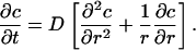
For growth of the adhesion zone, it is necessary for the zone to recruit binders to its advancing edge, so that the density immediately behind the front can be increased to c0. As binders are drawn from the free portion of the membrane in the immediate vicinity of the front at r = R(t)+, the local density falls to some level just ahead of the front, say c+ < c∞. This induces a density gradient (and, therefore, a chemical potential gradient) that tends to drive binder diffusion from more dense to less dense regions. If the local binder flux is proportional to the negative of the gradient in binder density with proportionality factor D > 0, and if binders are conserved throughout the free region R < r < ∞, then the concentration c(r,t) in that region is governed by the classical diffusion equation
 |
[3] |
A solution of this equation must satisfy the boundary condition c(R, t) = c+, the asymptotic condition c → c∞ as r → ∞, and the initial condition c(r, 0) = c∞. Free energy is dissipated in the course of binder diffusion, and this free-energy loss must be compensated by free-energy reduction due to bond formation.
A solution of the boundary value problem for c(r, t) in the region r > R(t) has the form of a similarity solution in which the adhesion-zone radius depends on time according to
 |
[4] |
as anticipated in the Introduction, and the binder density depends on r and t only through the combination η = r/R(t), namely,
 |
[5] |
where E1(·) is a standard exponential integral (21). This distribution solves the boundary value problem for any constant value of the parameter α.
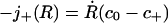
Note that the concentration boundary value c+ has not yet been related to system parameters. Its value follows from the physical requirement that binders must be conserved across the advancing front at r = R(t). Immediately behind the front, the binder density is uniformly c0 and the flux is zero. The flux immediately ahead of the front is j+(R) = -D∂c(r, t)/∂r|r→R(t)+. Binder conservation then requires that
 |
[6] |
identically in time. Substitution of the solution (5) into this conservation condition then yields.
 |
[7] |
by which the value of α is determined.
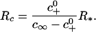
The task remaining is to determine the quantity c+ in terms of measurable system parameters. If diffusion of binders in the free part of the membrane is relatively fast, or if c∞ is near to c0 so that diffusion is unnecessary, then the rate of advance of the adhesion front is determined by the kinetics of binder flux across the front. In the situation being considered here, the mean density, c∞, is assumed to be substantially less than c0 within the adhesion zone so that diffusion of binders in the free portion of the membrane is the rate controlling feature of the process. Thus, the front advances with density at the level c+ just ahead of it, without energy dissipation within the edge. As is shown in the appendix, conservation of energy on the edge then requires that
 |
[8] |
where 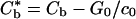 is a reduced or effective binding energy. For small values of γ/Rc0, which might correspond to either large radius, R, or small edge energy, γ, this expression has the simple approximate form
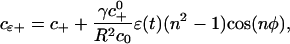
 |
[9] |
where  This observation leads to a definition of two separate, but related, length scales. First, the second term in the bracket in Eq. 9 is much smaller than the first term when R >> R*, where R* = γ/c0; when this condition is satisfied, c(r, t) given in Eq. 5 is an exact solution of the diffusion equation, since c+ is independent of R. Second, for the expansion of the adhesion zone to proceed, it is necessary to have c+ < c∞. It is evident from Eq. 9 that there is some lower bound on the radius below which this inequality cannot be satisfied. Equating c+ from Eq. 9 to c∞, this lower bound is found to be
 |
[10] |
Using typical values for the parameters γ = 1nm-1, ω = 102 nm2, c0 = 10-3 nm-2 (11), c∞ = 0.5c0, and  = 4, we find R* ≈ 1,000 nm and Rc ≈ 155 nm. The latter estimate is consistent with the critical nucleation radius (≈200 nm) observed in ref. 11. Also, since the experimental measurements of the time dependence of the front size in ref. 11 are reported for 103 nm ≤ R ≤ 104 nm, the condition R > R* is satisfied. The speed of the advancing front that can then be obtained from Eq. 4 and 7 is considered next.
With the knowledge of the binder density c+ ahead of the advancing front, the parameter α introduced in Eq. 4 can be computed by using Eq. 7. The dependence of this parameter on the ratio S ≡ (c∞ - c+)/(c0 - c+) is shown in the plot in Fig. 2. The figure shows that α increases rapidly when S ≥ 0.7 after a nearly linear increase from S = 0 to S = 0.7. Using the asymptotic expansion for Ei(α2) (21)
 |
[11] |
in Eq. 7, we find that α diverges as (1 - S)-1/2 when S approaches unity. Experimental work in ref. 11 shows a nearly linear increase in the parameter α for the RGD ligand concentration on the cell membrane in the range 0.08 to 0.2 mol %, in qualitative agreement with the behavior predicted in Fig. 2 for α ≤ 0.7. Experimental data for RGD concentrations close to but >0.2 mol % would be valuable for verification of the predicted square-root singularity in the functional form of α near S = 1. Also, the divergence in α implies that the square-root growth law will cease to hold when the binder number density on the cell membrane equals the surface density of ligands adsorbed on the substrate. As noted in the Introduction, the crossover from the square-root to the linear growth regime in the work of Boulbitch and coworkers (11) is observed when this criterion is satisfied.
Fig. 2.

The parameter α in Eq. 4 plotted as a function of S ≡ (c∞ - c+)/(c0 - c+). Note that α diverges when S approaches unity or, equivalently, when c∞ = c0.
Shape Stability of the Advancing Front
The stability of the advancing adhesion front can be studied by considering the evolution of small sinusoidal perturbations to the shape of the circular front taken to be of the form
 |
[12] |
where ε(t) is the amplitude of the perturbation and n is the wave or mode index. If the perturbation amplitude increases in time without bound, then the front is unstable, whereas decay of the perturbation indicates stability. Our goal is to derive conditions for stable growth of the front as a function of the mode index n and physical parameters. Also, in the case of an unstable front, the mode that grows at the fastest rate is of particular interest since it corresponds to the characteristic wave index observed in the optical images of the front (11). In what follows, we will derive a closed form expression for the fastest growing mode as a function of the radius of the front, the critical radius Rc, and the parameter α. Since all of these parameters are known from experimental measurements, the predictions of the fastest (or most unstable) wave index can be compared directly with the characteristic index inferred from the optical images.
The stability analysis is based on two assumptions: (i) we consider only small amplitude perturbations, that is, ε/R << 1, and (ii) we focus on the case where the parameter α derived from Eq. 7 is smaller than unity, which corresponds to the limit of slow front propagation. Whereas the former assumption leads to what is usually referred to as a linear stability analysis, the latter assumption allows for an analytic solution of the binder concentration ahead of the perturbed adhesion zone. Both of these assumption are satisfied in the experimental observations reported in ref. 11: The radius of a typical adhesion zone is 5 μm, whereas the amplitude of perturbations is only a fraction of a micrometer. For a typical RGD ligand concentration of 0.1 mol % and binder diffusion constant D = 10-12 m2/s, the fit to the square root growth law gives α ≈ 0.1.
To obtain the growth rate of the perturbed front as a function of the polar angle, we have to solve the diffusion equation (3) subject to the boundary conditions that c(r → ∞) = c∞ as in the case of the unperturbed case, but the concentration ahead of the advancing front has to account for the variation of the curvature along its perimeter. Using Eq. 9, this concentration is given by
 |
[13] |
where we have retained only the contribution linear in the perturbation amplitude ε(t). The variation of the concentration gradients along the perimeter of the adhesion zone alters the diffusive flux of the binders arriving at the front. Conservation of binders now satisfies the relation
 |
[14] |
from which one can deduce the time rate of the growth of the perturbation if the binder concentration is known. In the limit of small α, the concentration field that satisfies the boundary condition of Eq. 13 can be obtained as
 |
[15] |
from which the stability of the adhesion front can be studied.
The level curves of the concentration field in the vicinity of the curved front are shown in Fig. 3. It can be seen that the level curves are bunched together near the crests of the perturbation (e.g., point marked A in Fig. 3), compared with the troughs (point B), implying larger concentration gradients ahead of the front in the former case. The reason for the dependence of the gradients on the local curvature of the front can be understood on the basis of opposing effects, represented by the two terms in the square brackets in Eq. 15. The first term leads to a decrease (increase) in the binder concentration at the crests (troughs), whereas the opposite is true of the second term proportional to γ. The former term leads to shape instabilities of the advancing front, as the binder flux arriving at the crests is larger than the flux at the toughs, resulting in faster (slower) outward growth of the crests (troughs) leading to further increase in the amplitude of the perturbation. The term involving γ, on the other hand, tends to stabilize the front. The total growth rate of the perturbation due to these competing effects can be derived by using Eq. 15 in the binder conservation condition of Eq. 14 to obtain
 |
[16] |
The front is unstable to perturbations when the term in the square brackets is positive or when
 |
[17] |
where we have used the definition of the critical radius given in Eq. 10. For small R, note that the front motion is stable because of the stabilizing effect of the edge energy γ, whereas its influence diminishes at larger sizes. Also, for a given R, the growth rate of the perturbation increases with the wave index as n because of to the destabilizing effect, while it decreases as n3 because of the stabilizing effect of the edge energy. It follows that there is a wave index for which the growth rate is maximum. The mode with fastest rate of growth (for n >> 1) can be obtained from Eq. 16 as
 |
[18] |
Next, we compare the results of our stability analysis with experimental observations.
Fig. 3.

Level curves of binder concentration ahead of the perturbed edge. The inner contour shows the shape perturbation of the advancing circular adhesion front (Eq. 12). The physical parameters have been selected such that the instability condition given by Eq. 17 is satisfied. Note that the level curves are bunched up more closely at the crests (denoted by A) than at the troughs (B), implying that the concentration gradient ahead of the front is larger in the former case. The binder flux is, therefore, greater at the crests than the troughs, leading to faster outward growth of the crests and an increase in the amplitude of the perturbation.
In the diffusion-limited growth regime, Boulbitch and coworkers (11) report the shape of the advancing adhesion front to be rough with nearly uniformly spaced concave and convex regions. When the radius of the adhesion zone is about 8 μm, the optical images of the front show approximately nine periods of the modulation along the perimeter. Using Rc ≈ 200 nm and α = 0.1, Eq. 17 gives nmax ≈ 8, in good agreement with the experimental observations. We also point out that with increasing size of the adhesion zone, the wave index increases in magnitude, but the rate of its growth decreases as R-3/2. This result, which can be derived by substituting Eq. 18 in Eq. 16, is also consistent with the observations in ref. 11. In particular, as the adhesion zone increases in size, more periodic modulations of the front of smaller amplitude are observed in the square-root growth regime. In distinct contrast, when the front shows a linear growth law at a constant velocity, the perimeter is reported to be relatively smooth. We can understand this by noting that the instability in the square-root growth regime is mediated by the diffusion of binders. Since the growth of the adhesion zone does not involve binder diffusion along the cell membrane in the linear growth regime, the front motion should be stable against shape fluctuations.
Concluding Observations
In this article, we have considered the dynamics of adhesion fronts in cells and vesicles that grow as a result of binder flux that arrives at the front via intramembrane diffusion. We have shown that the binder diffusion-mediated front motion is unstable to perturbations in its shape. It is interesting to note that, from a mathematical perspective, the instability studied in the present work is similar to other instabilities studied in nonequilibrium physics (22, 23), where the interface motion is determined by solution of a partial differential equation (e.g., Euler or Navier–Stokes equation, Laplace equation, and heat equation). Examples include viscous fingering, crystal growth from a supercooled liquid, and propagation of flames. Similarities and differences between dendritic, fingering, and tip-splitting instabilities observed in different physical systems are discussed in ref. 22 along with a large collection of preprints in each area. Most of the experimental and theoretical work in these systems focuses on instabilities during the propagation of elongated fronts (usually parabolic), in contrast to the instabilities of a circular front studied here. In addition, whereas the physical effect that opposes the roughening of the front is the surface energy in most physical systems, in the case of advancing adhesion fronts it is the line energy arising from bending energy of the membrane and the interactions of the membrane with the glycocalyx.
Our attention in the present work has been restricted to linear stability analysis in the case where the front propagation is limited by kinetics of binder diffusion. In the future, we hope to carry out nonlinear numerical calculations for the evolution of large amplitude shape perturbations and further develop our theory to include the dissipative kinetics of binder attachment and detachment at the edge of the adhesion front. It would also be interesting to extend the present work to study the spreading of cells on substrates where complementary proteins are adsorbed on periodically patterned regions (15) or on substrates with regular arrays of geometric features such as a bed of microneedles to which cells can adhere (24). In the former case, depending on the size of the protein patterns on the substrate, the adhesion zone can assume the shape of the pattern (15) in contrast to the circular shape observed on unpatterned surfaces. An experimental study of the formation of cell–cell contacts mediated by cadherin, which is a lock and key molecule whose building unit is bound to the cytoskeleton, has been reported in a very recent article (25). In addition to diffusion of cadherins along the cell membrane, the elasticity of the cytoskeleton and the polymerization of the actin-network linked to the binders were found to play a prominent role in the formation of adhesive contacts. The addition of such a feature to the present model would make it more relevant to analysis of living cells.
Acknowledgments
This work was supported by National Science Foundation Grants CMS-0093714 and CMS-0210095 and Brown University Materials Research Science and Engineering Center Program Grant DMR-0079964.
Appendix
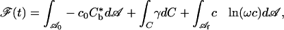
Here, the expression 8 is derived through examination of free-energy variations occurring during advance of the adhesion front. All contributions to the free energy are normalized by kBT. As described in the text, the free energy decreases within the bonded region of the plane, say  , by the amount c0Cb per unit area. Also, within this region, an amount of work sufficient to overcome the resistance of the glycocalyx has been expended; this work per unit area was denoted by G0. The free energy increases as a result of the combined effects of elastically deforming the membrane and overcoming the resistance of the glycocalyx as the membrane approaches the substrate. These effects come into play only in a narrow strip along the advancing edge of the adhesion zone. Consequently, it is assumed that this energy change is adequately represented by means of an energy per unit length γ (a line energy) along the plane curve at C that separates the bonded portion from the free portion of the membrane. Finally, within the free portion of the membrane, the binders are being continually redistributed through diffusion. A change in configurational or entropic free energy is associated with this redistribution. For a large set of identical, noninteracting elements, this entropic free-energy change is c ln(ωc) per unit area of membrane, where ω is a characteristic area that is on the order of the plane area of the binder molecule, say ≈100 nm2.
Denote the area of the free portion of the membrane by  . The free energy, say
  , is then given by
 |
[19] |
where  . Note that
  and
and  are time-dependent regions of the membrane. Time differentiation of 19, followed by an integration by parts of the resulting integral over
  , yields
 |
[20] |
where νn is the local normal speed of C into the region  , κ is the local curvature of C, n+ is a unit vector tangent to the membrane that is locally normal to C, and j+ is the limiting value of binder flux as C is approached from within
  . These parameters are necessarily related by
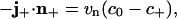 |
[21] |
which generalizes the corresponding conservation condition for a circular boundary given in 6 to the case of an arbitrarily shaped boundary C. The quantity Q(t) appearing on the left side of 20 is the (nonnegative) dissipation rate due to the diffusive intramembrane binder flux
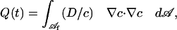 |
[22] |
where Δc is the spatial gradient of binder density within the membrane.
For a closed system, the rate of decrease in free energy equals the rate of dissipation. Assuming that the dissipation within the edge of the adhesion zone is zero,  from which it follows that the
 |
[23] |
The expression 8 follows from this result for the case when c+/c0 << 1.
Author contributions: V.B.S. and L.B.F. designed research, performed research, contributed new reagents/analytic tools, analyzed data, and wrote the paper.
Abbreviation: RGD, Arg-Gly-Asp.
References
- 1.Bell, G. I. (1978) Science 200, 618-627. [DOI] [PubMed] [Google Scholar]
- 2.Bell, G. I., Dembo, M. & Bongard, P. (1984) Biophys. J. 45, 1051-1064. [DOI] [PMC free article] [PubMed] [Google Scholar]
- 3.Bongrand, P. & Bell, G. I. (1984) in Cell Surface Dynamics: Concepts and Models, ed. Perelson, A. S., DeLisi, C. & Wiegel, F. W. (Dekker, New York), pp. 459-493.
- 4.Evan, E. A. (1984) Biophys. J. 48, 175-183. [Google Scholar]
- 5.Evan, E. A. (1984) Biophys. J. 48, 185-192. [Google Scholar]
- 6.Dembo, M., Torney, D. C., Saxman, K. & Hammer, D. (1988) Proc. R. Soc. London Ser. B 234, 55-83. [DOI] [PubMed] [Google Scholar]
- 7.Hammer, D. A. & Tirrell, M. (1996) Annu. Rev. Mater. Sci. 26, 651-691. [Google Scholar]
- 8.Bongrand, P. (1999) Rep. Prog. Phys. 62, 921-968. [Google Scholar]
- 9.Leckband, D. & Isrealachvili, J. (2001) Q. Rev. Biophys. 34, 105-267. [DOI] [PubMed] [Google Scholar]
- 10.Park, K., Mao, F. W. & Park, H. (1990) Biomaterials 11, 24-31. [DOI] [PubMed] [Google Scholar]
- 11.Boulbitch, A., Guttenberg, Z. & Sackmann, E. (2001) Biophys. J. 81, 2743-2751. [DOI] [PMC free article] [PubMed] [Google Scholar]
- 12.Guttenberg, Z., Lorz, B., Sackmann, E. & Boulbitch, A. (2001) Europhys. Lett. 54, 826-832. [Google Scholar]
- 13.Dustin, M., Fergawov, M., Chan, P., Springer, T. & Colan, T. (1996) J. Cell. Biol. 132, 465-474. [DOI] [PMC free article] [PubMed] [Google Scholar]
- 14.Smilenov, L. B., Mikhalov, A., Pelham, R. J., Marcantonio, E. E. & Gundersen, G. G. (1999) Science 286, 1172-1174. [DOI] [PubMed] [Google Scholar]
- 15.Cuvelier, D., Rossier, O., Bassereau, P. & Nassoy, P. (2003) Eur. Biophys. J. 32, 342-354. [DOI] [PubMed] [Google Scholar]
- 16.Arnold, M., Cavalcanti-Adam, E. A., Glass, R., Blummel, J., Eck, W., Kantlehner, M., Kessler, H. & Spatz, J. P. (2004) Chemphyschem 5, 383-388. [DOI] [PubMed] [Google Scholar]
- 17.Bruinsma, R., Behrisch, A. & Sackmann, E. (1999) Phys. Rev. E 61, 4253-4267. [DOI] [PubMed] [Google Scholar]
- 18.Komura, S. & Andelman, D. (2000) Eur. Phys. J. E 3, 259-271. [Google Scholar]
- 19.Brochard-Wyart, F. & de Gennes, P. G. (2002) Proc. Natl. Acad. Sci. USA 99, 7854-7859. [DOI] [PMC free article] [PubMed] [Google Scholar]
- 20.Freund, L. B. & Lin, Y. (2004) J. Mech. Phys. Solids 52, 2455-2472. [Google Scholar]
- 21.Abramowitz, M. & Stegun, I. A. (1965) Handbook of Mathematical Functions (Dover, New York), p. 228.
- 22.Pelce, P., ed. (1988) Dynamics of Curved Fronts (Academic, London).
- 23.Gollub, G. P. & Langer, J. S. (1999) Rev. Mod. Phys. 71, S396-S403. [Google Scholar]
- 24.Tan, J. L., Pirone, D. M., Gray, D. S., Bhadriraju, K. & Chen, C. S. (2003) Proc. Natl. Acad. Sci. USA 100, 1484-1489. [DOI] [PMC free article] [PubMed] [Google Scholar]
- 25.Delanoe-Ayari, H., Lenz, P., Brevier, J., Weidenhaupt, M., Vallade, M., Gulino, D., Joanny, J. F. & Riveline, D. (2004) Phys. Rev. Lett. 93, 108102. [DOI] [PubMed] [Google Scholar]