Abstract
Intron removal requires assembly of the spliceosome on pre-mRNA and extensive remodelling to form the spliceosome’s catalytic centre. Here we report the cryo-electron microscopy structure of the yeast pre-catalytic B complex spliceosome at near-atomic resolution. The mobile U2 snRNP associates with U4/U6.U5 tri-snRNP through U2/U6 helix II and an interface between U4/U6 di-snRNP and the U2 snRNP SF3b-containing domain, which also transiently contacts the helicase Brr2. The U2 snRNP 3’ region is flexibly attached to the SF3b-containing domain and protrudes over the concave surface of tri-snRNP, where the U1 snRNP may reside before its release from the pre-mRNA 5’-splice site. The U6 ACAGAGA sequence forms a hairpin which weakly tethers the 5’-splice site. B complex proteins Prp38, Snu23, and Spp381 bind the Prp8 N-terminal domain and stabilise U6 ACAGAGA stem–pre-mRNA and Brr2–U4 snRNA interactions. The results thus provide important insights into events leading to active site formation.
Pre-mRNA splicing is an important step in eukaryotic gene expression, whereby non-coding introns are removed from newly synthesized pre-mRNA by two step-wise trans-esterification reactions. Intron excision is catalysed by the spliceosome, a large and dynamic ribonucleoprotein particle (RNP) that assembles anew on each intron1. First, U1 and U2 snRNPs recognise the pre-mRNA 5’-splice site (5’SS) and the branch point sequence, forming the A complex, which associates with U4/U6.U5 tri-snRNP to form pre-B complex2. The 5'SS–U1 snRNP interaction is then disrupted by the helicase Prp28 (ref.3) and the 5’SS is transferred to the U6 snRNA ACAGAGA region4, forming the pre-catalytic B complex. Spliceosome activation requires the proteins Spp381, Prp38, and Snu23 (ref.5,6) and is initiated by ATP-dependent unwinding of the U4/U6 duplex by the helicase Brr2 (ref.7,8). During this process U4 snRNA and U4/U6 di-snRNP proteins dissociate9,10 and nineteen- and nineteen-related (NTC and NTR)9,11,12 complex proteins are recruited. U6 snRNA, freed from U4 snRNA, forms an internal stem loop and the U2/U6 helix I with U2 snRNA13, yielding the catalytic RNA centre that harbours the catalytic metal ions14,15. This activated spliceosome, Bact, is then converted to B*, positioning the branch point adenosine at the 5’SS for step 1 of splicing (branching). The resultant C complex is remodelled to C*, bringing the 5’- and 3’-exons into proximity for step 2 of splicing (exon ligation)16,17. Ligated mRNA is then released and the intron-lariat spliceosome (ILS) is disassembled to recycle snRNPs for further splicing rounds.
Recent cryo-electron microscopy (cryo-EM) studies of yeast18–23 and human spliceosomes24 have provided unprecedented insights into the catalytic stages of splicing. The group II intron-like catalytic RNA centre is fully formed in Bact (ref.20,21) with pre-mRNA 5’SS positioned near the catalytic metals and the branch point adenosine located 50Å away. The C and C* complex structures18,19,22–24 revealed step I and step II conformations and the functions of step-specific factors. In contrast, the molecular details prior to the catalytic stages are less well understood. Although the structures of isolated tri-snRNP25–27 and several U2 snRNP parts are available21,28–30, low resolution structures of complete yeast9,31 and human32,33 pre-catalytic spliceosomes provided only limited insights into their assembly and activation.
Here we report the cryo-EM structure of the pre-catalytic B-complex from the yeast Saccharomyces cerevisiae at near-atomic resolution, revealing the complete U2 snRNP architecture and its interactions with U4/U6.U5 tri-snRNP. Comparison with the yeast Bact structure20,21 provides crucial insights into the mechanism of spliceosome activation.
Overall architecture and U2 snRNP
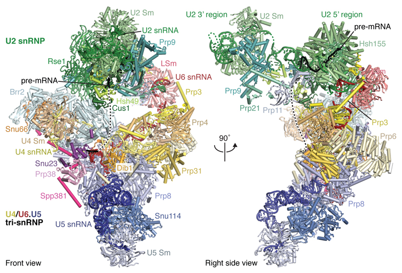
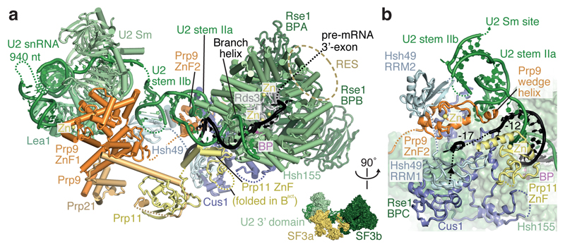
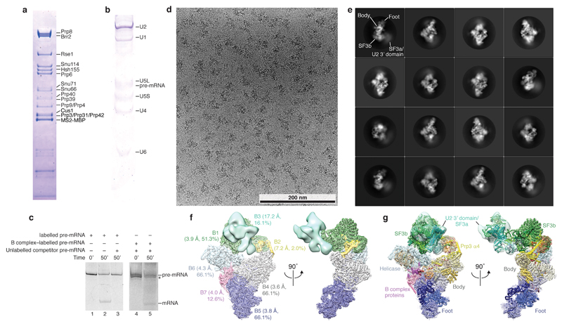
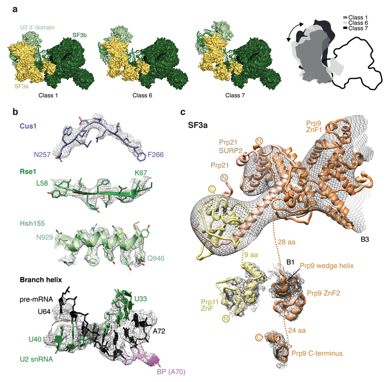
We assembled spliceosomes on UBC4 pre-mRNA and stalled at the B complex stage by limiting ATP concentration9,34 (Methods). Spliceosomes were imaged under cryogenic conditions yielding 496,581 single particle images (Extended Data Fig. 1d). Several rounds of unsupervised 2D and 3D particle sorting, focused refinement, and signal subtraction produced cryo-EM densities for the complete B-complex structure (Fig. 1, Extended Data Figs 1e, f, 2, 3, Methods) ranging from 3.6–17.2 Å resolution (maps B1-7). In B complex the U2 snRNP resides between the tri-snRNP ‘head’ and ‘arm’ regions26,27, in agreement with low-resolution studies of yeast and human complexes31,32,35 (Fig. 1, Supplementary information). B complex has a concave shape, formed in part by the U2 snRNP that protrudes over the tri-snRNP region, where the catalytic centre will be created. The yeast U2 snRNP contains 18 proteins, divided into 7 Sm proteins, the Msl1-Lea1 hetero-dimer, SF3a (Prp9, Prp11, Prp21), and SF3b (Hsh155, Rse1, Cus1, Hsh49, Rds3, Ysf3) subcomplexes (Fig. 2a, Extended Data Fig. 4). Consistent with negative stain EM of its human counterpart36 the yeast U2 snRNP has a bipartite structure, consisting of 5’ (or SF3b-bound) and 3’ domains (Sm core domain and the Msl1-Lea1 dimer). The elongated SF3a subcomplex bridges the two domains, and U2 snRNA in between adopts the stem IIa/b configuration1 (Fig. 2a, Extended Data Fig. 4c). The SF3b subcomplex is organised around Rse1, comprising three β-propeller domains BPA, BPB, and BPC, and the split washer-shaped HEAT-repeat protein Hsh155 that together envelop Ysf3 and the Zn-containing Rds320,21,30. The pre-mRNA branch point sequence and U2 snRNA form the branch helix, which is wedged into the split ends of the Hsh155 HEAT-repeats as in Bact (ref.20,21). The nucleotide base of the branch point adenosine (A70) is flipped out of the branch helix and makes contact with Tyr35 of Rds3 and a pocket formed by HEAT repeats H15-17 of Hsh155 as in Bact.
Figure 1. B complex structure at near-atomic resolution.
Two orthogonal views of the B complex structure. Subunits are coloured according to snRNP identity (U2, green; U4, yellow; U5, blue; U6, red; Dib1, Prp6 and Snu66, shades of yellow). B complex proteins in shades of magenta (Spp381, magenta; Prp38, light magenta; Snu23, violet).
Figure 2. U2 snRNP architecture and interactions with the intron.
a, Organisation of the U2 snRNP with subunits coloured as in Fig. 1, except for Prp9 (orange), Prp11 (yellow), Prp21 (light orange), Cus1 (dark blue), Hsh49 (light blue), Rds3 (grey), and the branch point (BP) adenosine (magenta). The thumbnail highlights the U2 snRNP subcomplexes. The RES complex location (dashed brown ellipse) is indicated based on its Bact location20,21. The non-essential 940-nucleotide insertion in yeast U2 snRNA50 is disordered. A loop in the Prp11 Zn-finger (ZnF) domain is disordered in B complex, but folds over the pre-mRNA 5’SS in Bact (ref.21). b, SF3a/b proteins chaperone U2 snRNA elements and the pre-mRNA intron. The SF3a Prp9 subunit ‘wedge helix’ separates the intron from U2 snRNA, guiding it towards Hsh49 RRM1. Pre-mRNA nucleotides at position –12 and –17 from the branch point (BP) adenosine and its 3’-direction (black arrow) are indicated. Colours as in a.
The U2 3’ domain and SF3a subcomplexes associate via contacts between the Prp9 Zn-finger 1 (ZnF1) and U2 Sm ring subunits SmD1 and SmD2. SF3a bridges the 5’ and 3’ domains36 via the conserved Prp9 ZnF2 and Prp11 ZnF, which are anchored largely by SF3b subunit Cus1, U2 snRNA stem IIa/b, and the intron (Fig. 2b). This explains why the Prp9 ZnF2 and Prp11 ZnF are required for SF3a integration into the human U2 snRNP and for A complex assembly37. The intron upstream of the branch helix is chaperoned by the Prp11 ZnF and a conserved α-helix in Prp9 (residues 407-415) that we term ‘wedge helix’ (Fig. 2b). The wedge helix binds U2 stem IIa, and separates the intron (position –12 from the branch point) from U2 snRNA, guiding the intron towards its binding site on the SF3b Hsh49 RNA recognition motif 1 (RRM1) (around position –17). Hsh49 RRM1 connects to RRM2, which rests on top of the Prp9 ZnF2 domain and binds U2 stem IIb. Thus, both Hsh49 RRM domains bind to RNA, and mutation of these interfaces is lethal in yeast38. The SF3b protein Cus1 forms an extended polypeptide that folds onto Hsh155 H16-20 and the Rse1 BPC. Anchored at this site, Cus1 (residues 290-353) forms a globular domain with Hsh49 RRM1 (ref.28) and nearby Cus1 regions bind Prp9 ZnF2, Prp11 ZnF as well as U2 stem IIa (Fig. 2b). Cus1 thereby scaffolds key U2 snRNA and pre-mRNA interactions. The structure thus reveals how SF3a and SF3b form an intricate network of protein-RNA interactions to chaperone U2 snRNA and the intron38–41.
B complex stabilization
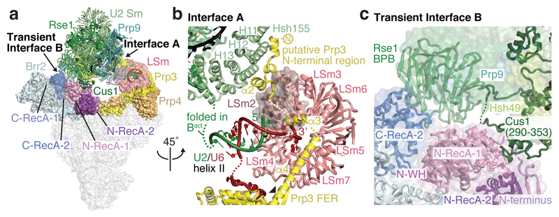
The U2 snRNP 5’ domain binds to tri-snRNP through two interfaces (A and B, Fig. 3a, Extended Data Fig. 5a). In interface A, the SF3b subunit Hsh155 binds to the U4/U6 di-snRNP protein Prp3 (Fig. 3b). A long α-helix of Prp3 (α4) extends from the Prp4 β-propeller domain toward the U6 LSm ring (LSm5 and LSm7 subunits), reaches across the LSm ring, and inserts its putative N-terminal helices between the LSm ring subunit LSm2 and the Hsh155 HEAT repeats H11-13 (Fig. 3a, b). Interface A further involves U2/U6 helix II13, comprising the 3’-end of U6 snRNA and the 5’-end of U2 snRNA. U6 snRNA thereby tethers U2 and U5 snRNPs during spliceosome activation, when U4/U6 duplex unwinding and additional remodelling occurs. Importantly, the U2 snRNA nucleotides that form the active site U2/U6 helix I in Bact remain disordered in B complex and available for pairing with U6 snRNA during activation.
Figure 3. U2 snRNP and tri-snRNP interfaces.
a, Overview of the B complex structure, showing interface A and transient interface B. The U2 snRNP (coloured as in Fig. 1) was positioned relative to tri-snRNP using a subset of particles (map B2) (see Methods). Tri-snRNP is shown as a surface (grey), except for Prp3 (yellow), Prp4 (light orange), the LSm ring (salmon) and Brr2 (pale cyan except for N-terminal and C-terminal RecA-1 and RecA-2 lobes shown in shades of blue and violet). b, Interface A. The U2 snRNP binds tri-snRNP via U2/U6 helix II and SF3b subunit Hsh155 HEAT repeats H11-13, which bind the putative Prp3 N-terminal region. The nucleotides that form the active site U2/U6 helix I in Bact are disordered (dashed green line). The black triangle indicates the region of Prp3 helix α4 that bends with different U2 snRNP positions. See Extended Data Fig. 5. c, Transient Interface B. SF3b subunits Cus1 and Rse1 BPB contact Brr2 in a subset of cryo-EM particles (see Extended Data Fig. 5a; Methods). Colours as in a.
Interface B is transient and found only in a subgroup of cryo-EM particles (map B2) (Fig. 3a, c, Extended Data Figs 2, 5a, Methods). This interface involves weak protein contacts between Cus1 (residues 328-353) and the RecA-1 lobe of the N-terminal helicase cassette (NHC) of Brr2 as well as between the Rse1 BPB and RecA-1 of NHC and RecA-2 of the C-terminal helicase cassette (CHC) of Brr2. The mobility of interface B may be important to allow SF3b and Brr2 to move independently during spliceosome activation.
B complex protein interactions
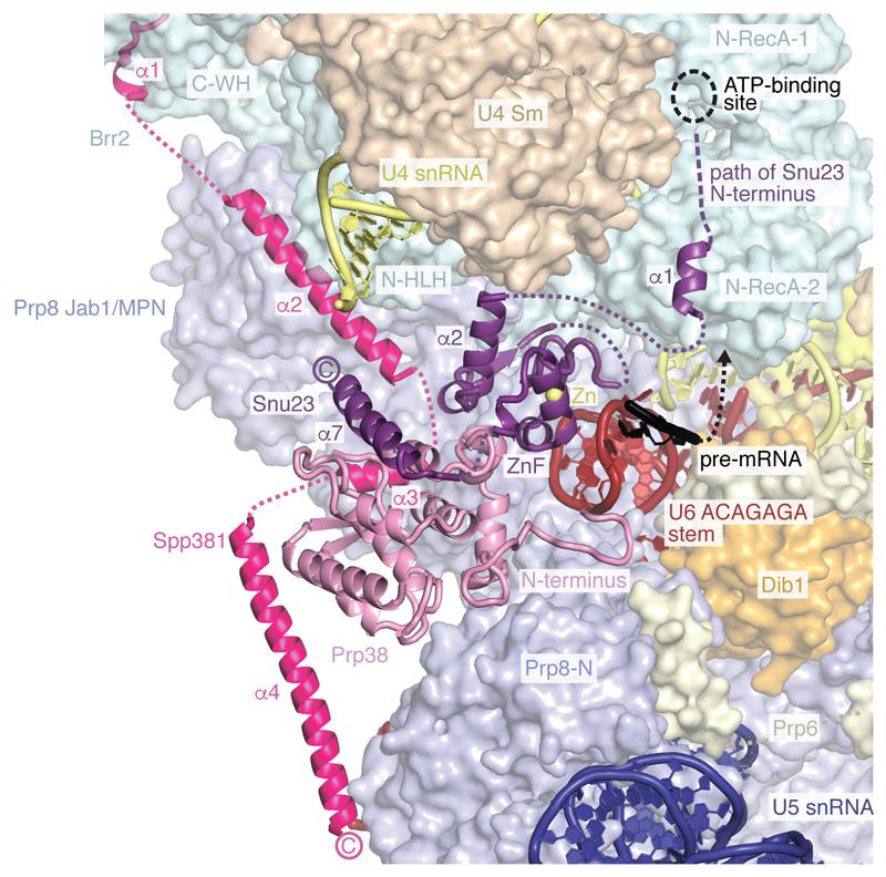
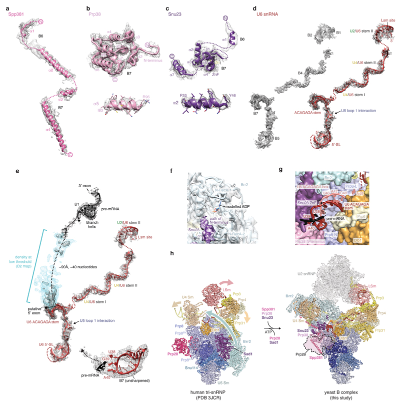
Spp381, Prp38, and Snu23 are required for spliceosome activation and important for viability in yeast5,42,43. These proteins are B complex-specific in humans44, whereas they associate with isolated U4/U6.U5 tri-snRNP in yeast6,43,45, and are hereafter called B complex proteins. We obtained a reconstruction of the mobile B complex with a local resolution of 4.0-5.0 Å from a subset of cryo-EM particles by focused classification (map B7) (Fig. 4, Extended Data Figs 1g, f, 2, and 6). Previously, this density was either not interpreted26 or tentatively attributed to part of Snu66 (ref.27). Prp38 scaffolds Spp381 and Snu23 (ref.46), and anchors these proteins at the Prp8 N-terminal domain (Prp8N), consistent with biochemical data26,31 (Fig. 4). The Spp381 N-terminal region binds the winged helix (WH) domain of the Brr2 CHC, and continues between the Prp8 Jab1/MPN domain and the helix-loop-helix (HLH) domain of the Brr2 NHC with its long α-helix 2 (Fig. 4). The Spp381 C-terminal region then binds along the globular Prp38 domain as its human counterpart46 and extends towards Prp8N. This explains why deletion of the Spp381 N-terminal region impairs splicing, and why Spp381 can rescue the prp38-1 temperature-sensitive mutation5. Snu23 contains a conserved ZnF domain that binds Prp38 and the major groove of the U6 snRNA ACAGAGA stem to stabilise it (Fig. 4). The Snu23 N-terminus binds the RecA-2 lobe of the Brr2 NHC and reaches near the NHC RecA-1 ATP-binding pocket. Snu23 may thereby stabilise Brr2 on the U4 snRNA substrate and influence Brr2 helicase activity (Extended Data Fig. 6f). Thus Spp381 and Snu23 together, held by Prp38, aid in positioning Brr2 to one side of tri-snRNP. Consistent with the structure, several Prp8 mutations that suppress the U4-cs1 mutant47, which blocks U4/U6 unwinding, map near Prp8–B complex protein interfaces.
Figure 4. B complex proteins stabilise Brr2 and U6 snRNA.
B complex protein interactions within the pre-catalytic B complex. The extended structures of B complex proteins Spp381 (magenta), Prp38 (light magenta), and Snu23 (violet) bind the Prp8 N-terminal (Prp8N) domain and contact Prp8 Jab1/MPN, Brr2 C-WH, N-HLH, and N-RecA-2 domains to position Brr2 on U4 snRNA. The Snu23 Zn-finger (ZnF) and Prp38 N-terminus stabilise the U6 ACAGAGA stem, which may enable tethering of the putative pre-mRNA 5’SS at its tip (3’-direction, black arrow).
In B complex the 5’-stem loop of U6 snRNA binds the Prp8N domain and the adjacent U6 nucleotides basepair with U5 loop 1. Consistent with this, U5 snRNA loop 1 nucleotides crosslink to a wide region surrounding the pre-mRNA 5’SS in B complex, suggesting that the 5’SS is in the vicinity of U5 loop 1 but does not basepair with it48. Pre-mRNA also does not crosslink to U5 loop 1 in the purified human B complex2. U6 snRNA continues past U5 loop 1 to form the ACAGAGA stem (map B7 and ref.27) and is stabilised by the Snu23 ZnF domain, the extended Prp38 N-terminus, and tri-snRNP proteins Dib1, Prp6, and Prp8 (Fig. 4, Extended Data Fig. 6g). Destabilisation of these interactions by mutations of the Prp38-Snu23 ZnF5 interface and the Snu23 ZnF domain43 causes growth defects in yeast. The base of the U6 snRNA ACAGAGA stem is further enclosed by the previously disordered Prp8 residues 2121-2140 (ref.26,27) that form a β-hairpin, to which Snu23 adds a β-strand. A weak density (maps B2, B7) connects from the tip of the U6 ACAGAGA stem to the SF3b-bound intron (Extended Data Fig. 6e), approximately 90 Å apart, and together with RNA crosslinking2,48 suggests that this is pre-mRNA near the 5’SS. Taken together, the structure indicates that the extensive interactions involving the B complex proteins stabilise Brr2 on U4 snRNA and the weak tethering of the putative 5’SS to U6 snRNA prior to spliceosome activation.
B complex assembly
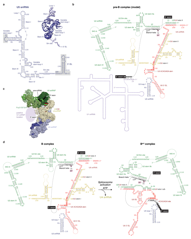
Comparisons of yeast B complex and negative stain EM projections of human B complex2,32 reveal a conserved architecture, including the location of the Brr2 helicase (called ‘stump’ domain in ref.2,31), suggesting that events before B complex formation may also be conserved. In the human system, an ATPase-deficient mutant of Prp28 accumulates the pre-B complex2, where U1 snRNA remains paired to the 5’SS3 (Extended Data Fig. 7). In human U4/U6.U5 tri-snRNP Prp28 binds the Prp8N and Prp8 Endonuclease (Prp8EN) domains and Sad1 and tethers the Brr2 helicase distant from its U4 snRNA substrate25. Importantly, the Prp28 binding site is altered and overlaps with that of the B complex proteins in yeast B complex (Extended Data Fig. 6h). This suggests that Prp28 is released subsequent to disrupting the U1 snRNA–pre-mRNA interaction, to allow the recruitment of the B complex-specific proteins to the Prp8N domain and binding and repositioning of the helicase Brr2 to its B complex location on U4 snRNA (Extended Data Fig. 6h). The U6 ACAGAGA stem is subsequently stabilised by the B complex proteins to allow tethering of the 5’SS near the tip of the stem prior to activation, consistent with crosslinking48. Prp28 and Sad1 exist in both yeast and humans, suggesting that conversion from pre-B to B complexes is a conserved feature of splicing. We also note that the surprisingly large space between opposite ends of the concave B complex structure may accommodate the U1 snRNP during early spliceosome assembly (Extended Data Fig. 7c) and allow for structural rearrangements during spliceosome activation.
Model of spliceosome activation
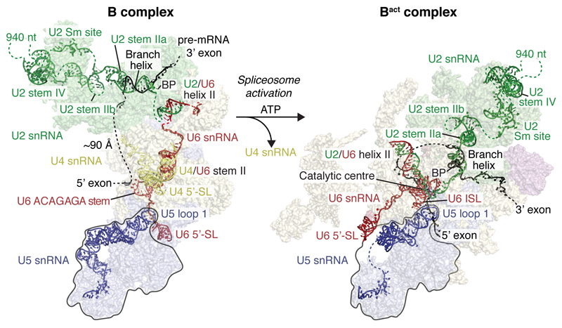
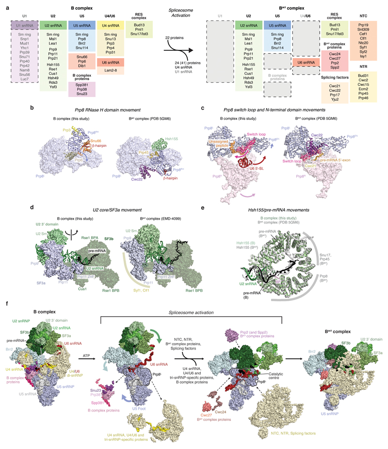
Comparison of the yeast B complex structure presented here with the yeast Bact structure20,21 leads to a more detailed model for spliceosome activation (Fig. 5, 6, Extended Data Fig. 7d, 8). In B complex, the helicase Brr2 is positioned by the B complex proteins and engaged with the U4 snRNA substrate. The 3’-end of U6 snRNA is held by pairing with U2 snRNA, while the 5’-stem of U6 snRNA is anchored to the Prp8N domain. Spliceosome activation is initiated by ATP-dependent translocation of Brr2 along U4 snRNA. Unwinding of the U4/U6 duplex exposes the central region of U6 snRNA, which may fold spontaneously to form the U6 snRNA internal stem loop. The disordered single-stranded region of U2 snRNA in B complex (Fig. 3b) then pairs with U6 snRNA to form U2/U6 helix 1a and 1b (ref.13), followed by formation of the catalytic U2/U6 triplex to complete the catalytic RNA centre49 (Fig. 6). The loss of U4 snRNA and U4/U6 di-snRNP proteins together with formation of the catalytic centre may induce a large movement of the U2 snRNP towards the Prp8 Large (Prp8L) domain, and facilitate a new contact between the SF3b Rse1 BPB and Brr2, which also moves from its B complex location (Fig. 6). The B complex proteins may detach from Brr2 in this new position, due to a steric clash with the Prp8EN domain. This uncovers the binding site for Bact-specific proteins Cwc24 and Cwc27 at the Prp8N and Prp8EN domains, which stabilise the new interaction network. Our model suggests that the folding energy of the catalytic RNA core alone could mediate several of the observed remodelling events (Fig. 6) and promote the binding of stabilising Bact, NTC, and NTR proteins.
Figure 5. Changes in the RNA network during spliceosome activation.
B and Bact complexes with RNA models superimposed on transparent surfaces of spliceosome proteins. Proteins are coloured as in Fig. 1, and the two structures are aligned with their U5 snRNP foot domain (black outline). The U2 3’ domain and SF3a proteins are modelled based on a low-pass filtered Bact cryo-EM density20 (EMD-4099, see Methods) onto the Bact model21 (PDB ID 5GM6). Internal stem loop, ISL; Stem loop, SL.
Figure 6. Model for spliceosome activation from B to Bact complex.
The ATP-dependent activity of Brr2 results in release of U4 snRNA, U4/U6, and tri-snRNP-specifc proteins (transition I), followed by U6 Internal stem loop (ISL) folding and U6 ACAGAGA stem unfolding (II), formation of U2/U6 helix I, ACAGAGA helix, the 5’-exon–U5 loop I basepairs (III), and the binding of the NTC, NTR and Bact complex proteins (IV). Proposed activation intermediates are shown in a grey box. See also Extended Data Figs 7d and 8.
Prior to activation, U6 snRNA binds Prp8N with its 5’-stem, passes over U5 loop 1, and forms the U6 ACAGAGA stem, where it tethers the pre-mRNA near its 5’SS. U4/U6 unwinding together with the loss of U4/U6 di-snRNP and tri-snRNP-specific proteins, and destabilization of B complex proteins allow the U6 5’-stem to reposition to the opposite side of the complex (Fig. 5), where NTR proteins Bud31, Ecm2, and Cwc2 anchor it onto Prp8N in Bact. These remodelling events free U5 loop 1 from U6 snRNA and together destabilise the U6 ACAGAGA stem. The tethered 5’-exon and 5’SS can now be recognized by the exposed U6 ACAGAGA box and U5 loop 1. The 5’-exon is then loaded in the newly created exon channel, formed by rotation of the U5 foot domain and association of Cwc21 and Cwc22 (ref.18) (Extended Data Fig. 8). A loop of SF3a subunit Prp11 folds in Bact and together with Cwc24 shields the 5’SS from the active site, while the SF3b-bound branch helix is immobilized 50 Å away, ready for Prp2-mediated conversion to B* and step I of splicing18.
Activation in yeast, from B to Bact complex spliceosomes, involves the release of 24 proteins9,31 and the recruitment of 22 others (Extended Data Fig. 8a) plus extensive rearrangements of the RNA network. Detailed structural knowledge of both B and Bact complexes now provides a framework to dissect the activation mechanism and to determine the precise order of molecular events leading to formation of the spliceosome active site.
Methods
Preparation and purification of B complex
To prepare B complex spliceosomes for structural study, we grew yeast Saccharomyces cerevisiae containing a TAPS affinity tag on Brr2 (ref.51) in a 120 L fermenter. Splicing extract was prepared using the liquid nitrogen method essentially as described52, with an additional 18 h dialysis against buffer A (20 mM HEPES (pH 7.9), 50 mM KCl, 20% glycerol, 0.2 mM EDTA, 0.5 mM DTT), to deplete ATP. UBC4 pre-mRNA53 containing two MS2 stem loops at the 5’-end was made by in vitro transcription. The RNA product was subsequently labelled with fluorescein54 at its 3’-end to monitor complex purification. In vitro splicing reactions were assembled from pre-mRNA substrate pre-bound to MS2-MBP fusion protein as described55. Splicing reactions contained 50 µM ATP to stall splicing at the B complex stage as described9,34, and proceeded for 50 min at 23 ºC. The reaction mixture was centrifuged through a 40% glycerol cushion in buffer B (20 mM HEPES (pH 7.9), 50 mM KCl, 1% glycerol, 0.2 mM EDTA, 1 mM DTT, 0.04% NP-40). The cushion was collected, diluted with buffer B, and applied to amylose resin (NEB) pre-washed with buffer C (20 mM HEPES (pH 7.9), 75 mM KCl, 5% glycerol, 0.2 mM EDTA, 1 mM DTT, 0.03% NP-40). After 12 h incubation at 4ºC, the resin was washed with buffer C and eluted in buffer C containing 50 mM KCl and 12 mM Maltose. Fractions containing spliceosomes were pooled and applied to Strep-Tactin resin (GE Healthcare), pre-washed with buffer C, and incubated for 4 h at 4 ºC. The resin was washed with buffer C, and the sample was eluted with buffer D (20 mM HEPES (pH 7.9), 50 mM KCl, 0.2 mM EDTA, 1 mM DTT, 2.5 mM desthiobiotin). Fractions containing spliceosomes were pooled and crosslinked using 1 mM BS3 (Sigma) on ice for 1 h, and subsequently quenched with 50 mM Ammonium bicarbonate. The sample was concentrated to ~1.5 mg mL-1 and immediately used for EM sample preparation. The isolated complexes contained U2, U4, U5, U6 snRNA and pre-mRNA, and all proteins previously assigned to pre-catalytic spliceosomes9,31. The U1 snRNP was identified in sub-stoichiometric amounts, consistent with its destabilization in B complex2,31 (Extended Data Fig. 1a, b).
To confirm that purified B complex spliceosomes were functional, we carried out an in vitro splicing assay. B complex was prepared as for EM studies using labelled UBC4 pre-mRNA, but was not crosslinked, and was flash-frozen in liquid nitrogen and stored at -80 ºC until further use. In vitro splicing was carried out in the presence of 2 mM ATP and unlabelled 60 nM pre-mRNA competitor, inhibiting de novo spliceosome assembly. Purified B complex was incubated with nuclear extract for 10 min before adding ATP, and product formation was visualized after 50 min of splicing at 23 ºC on a denaturing 18% TBE gel with a Typhoon scanner (GE Healthcare) (Extended Data Fig. 1c).
Electron microscopy
B complex spliceosomes were studied by negative stain EM. Copper grids (Quantifoil) were coated with a ~10 nm homemade carbon film and glow-discharged 20 s before deposition of 3.5 µL sample (0.15 mg mL-1). The sample was incubated for 1 min and grids were blotted with three 3.5 µL drops of distilled water. The sample was stained in a 3.5 µL drop of saturated uranyl formate solution for 1 min, and blotted until dry. 409 images were recorded using a FEI Spirit microscope operated at 120 kV and a 2k×2k CCD camera with a defocus of approximately 1.5 µm and a nominal magnification of 26,000 (3.84 Å pixel-1).
For cryo-EM analysis the sample was applied to R1.2/1.3 holey carbon grids (Quantifoil) and coated with a 5–7 nm homemade carbon film. Grids were glow-discharged for 15 s before deposition of 3 µL sample (~1.5 mg mL-1), and subsequently incubated for 2–3.5 s before blotting and vitrification by plunging into liquid ethane with a Vitrobot Mark III (FEI) operated at 4 °C and 100% humidity. Cryo-EM data was acquired on a FEI Titan Krios operated in EFTEM mode at 300 keV, equipped with a K2 Summit direct detector (Gatan) and a GIF Quantum energy filter (slit width of 20 eV, Gatan). Data acquisition was carried out with Digital Micrograph (Gatan) to record 5,115 movies with a defocus range of –0.35 µm to –5.3 µm at a nominal magnification of 81,000 (1.43 Å pixel–1). The camera was operated in ‘super-resolution’ mode (0.715 Å pixel–1) with a total exposure time of 16 s fractionated into 20 frames, a dose rate of ~1.25 e− pixel–1 s–1, and a total dose of 56 e−Å−2 per movie. Movies were binned once and aligned using MOTIONCORR56.
Image processing
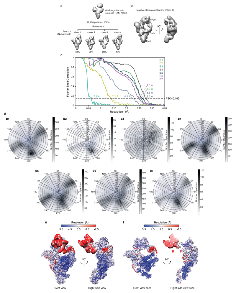
For single particles analysis CTF parameters were estimated using CTFFIND4 (ref.57) and CTF correction and subsequent image processing were carried out using RELION 2.0 beta58, unless otherwise noted. Resolution is reported based on the gold-standard Fourier shell correlation (FSC) (0.143 criterion) as described59 and temperature factors were determined and applied automatically in RELION58. For negative stain analysis 12,229 particles were selected semi-automatically using e2boxer.py from EMAN260, extracted using a 1762 pixel box and pre-processed to normalize the images. The negative stain map of human BΔU1 (ref.32) (EMD-1066) was used as an initial reference for three-dimensional (3D) refinement of the 12,229 particles set. A single round of 3D classification revealed a B complex density from 3,707 particles (Extended Data Fig. 3) that was refined to an estimated resolution of 50 Å (Extended Data Fig. 3b). This density was low-pass filtered to 60 Å and used for processing of cryo-EM data.
For cryo-EM analysis an initial set of 7,208 particles were selected semi-automatically using e2boxer.py60, and extracted with a 4802 pixel box and pre-processed to normalize the images. Reference-free two-dimensional (2D) class averages were calculated and filtered to 30 Å resolution and used for automated picking in RELION61 of all micrographs. The resulting particles were screened manually and by reference-free 2D classification, yielding 496,581 particles for subsequent processing. A 3D reconstruction of all particles was calculated to an overall resolution of 4 Å, and subjected to particle polishing in RELION58, improving the resolution to 3.7 Å.
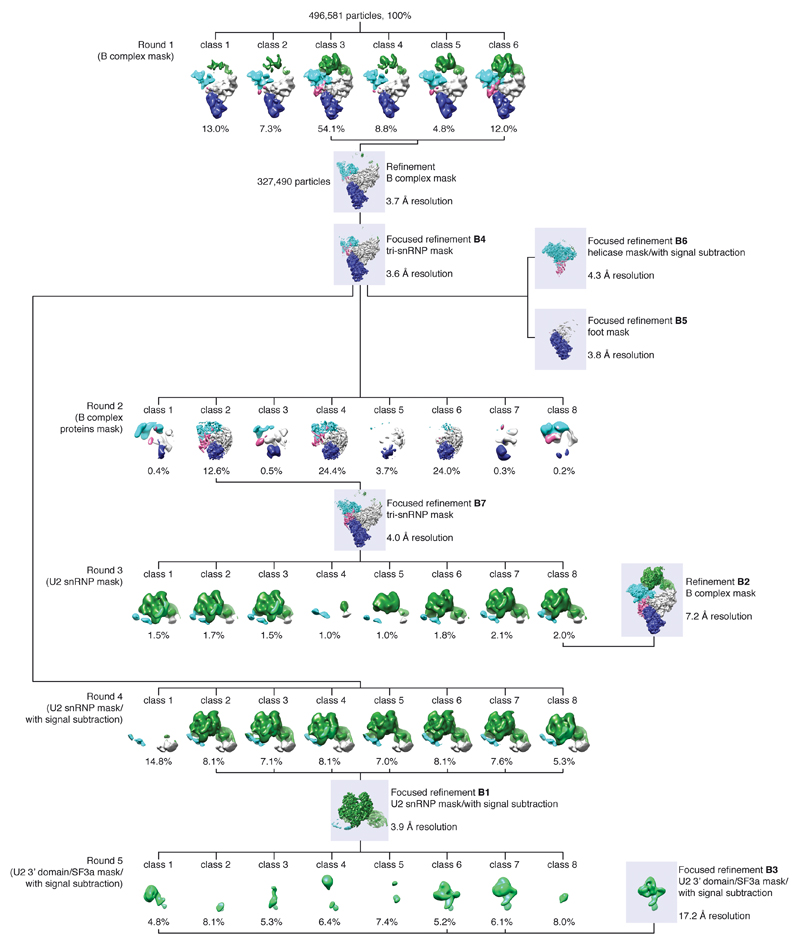
Hierarchical 3D classification was carried out without image alignment to reduce computational costs and identify homogenous particle groups (Extended Data Fig. 2). Soft masks enveloping complete B complex or smaller regions were generated using the volume eraser in UCSF Chimera62 and RELION58. This included masks for tri-snRNP (excluding the helicase domain), B complex proteins, U2 snRNP SF3b and U2 3’ domain/SF3a subcomplexes. Each resultant class was refined using the 3D auto-refine procedure against the respective particles within that class with a soft reference mask in the shape of the feature of interest, yielding B1-7 reconstructions (Extended Data Figs 1e, 2, and 3c, d). To improve the resolution of regions with weak density, we used focused refinements (B4, B5, B7) together with signal subtraction (B1, B3, B6) as described63. The B1 reconstruction (improved SF3b density) was calculated in a focused refinement from 254,095 particles from which the tri-snRNP signal was subtracted63, and was determined to a resolution of 3.9 Å with a temperature factor of -125. The B2 reconstruction was determined from 9,559 particles to a resolution of 7.2 Å with a temperature factor of -170, and was used to determine the relative positions of U2 snRNP and tri-snRNP for the complete B complex model (see Structural Modelling). The B3 reconstruction (improved U2 3’ domain/SF3a densities) was calculated in a focused refinement from 79,166 particles from which the U2 snRNP SF3b and tri-snRNP signal was subtracted63, and was determined to a resolution of 17.2 Å with a temperature factor of -200. The low resolution of the B3 density is likely due to flexibility of the U2 3’ domain relative to SF3a. The B4 reconstruction (improved tri-snRNP body density) was calculated in a focused refinement from 327,490 particles to a resolution of 3.6 Å with a temperature factor of -105. The B5 reconstruction (improved tri-snRNP foot domain density) was calculated in a focused refinement from 327,490 particles to a resolution of 3.8 Å with a temperature factor of -127. The B6 reconstruction (improved helicase density) was calculated in a focused refinement from 327,490 particles from which the tri-snRNP signal, excluding the helicase domain, was subtracted63, and was determined to a resolution of 4.3 Å with a temperature factor of -140. The B7 reconstruction (improved B complex protein density) was calculated in a focused refinement from 62,406 particles to a resolution of 4.0 Å with a temperature factor of -80. Local resolution estimates were determined using ResMap64 (Extended Data Fig. 3e, f).
Structural Modelling
A composite model of B complex was obtained using B1 to B7 densities (Extended Data Fig. 1f, g, 9, Extended Data Table 1). Model building was carried out in COOT65. Coordinates were refined in real space using phenix.real_space_refine in PHENIX66 into the respective sharpened density, applying secondary structure, rotamer, nucleic acid, and metal coordination restraints, unless otherwise noted (Extended Data Fig. 9). The Bact SF3b and Prp11 ZnF cryo-EM model21 (PDB 5GM6) was fitted into the B1 density and adjusted. We additionally modelled the conserved Prp9 ZnF2, Prp9 C-terminus (residues 503-528), Cus1 N- and C-terminal regions, U2 snRNA stem IIb, and re-assigned Hsh49 RRM2. The Cus1(residues 290-368)-Hsh49 RRM1 crystal structure28 was fitted into the B1 density and adjusted. The pre-mRNA sequence was changed to that of UBC4 and an altered pre-mRNA path downstream from the branch point adenosine could be determined (Extended Data Fig. 8e). Further, the crystal structure of the LSm ring67 (PDB ID 4M7A) could be fitted in a unique orientation in the B1 density and the putative Prp3 N-terminal region (residues 35-71) as well as a poly-alanine model of Prp3 helix α3, bridging SF3b to the LSm ring, were modelled. The amino acid register for Prp3 residues 35-138 is uncertain. A homology model of the yeast Sm ring was generated based on the human Sm ring68 (PDB ID 4WZJ) using MODELLER69 and was fitted into B5 and B6 maps for U5 and U4 snRNPs, respectively, and adjusted. The cryo-EM structure of the U2 3’ domain from C complex18, where the Sm ring was replaced with the adjusted MODELLER69 model, and the SF3a crystal structure29, where selenomethionine residues were changed to the original protein sequence in COOT65, were fitted automatically into the B3 density using a global 6D search in Situs70. The U2 3’ domain/SF3a complex was positioned relative to SF3b (B1 density) by fitting into the reconstruction from round 5 class 6 (Extended Data Fig. 2). This yielded a model for the complete U2 snRNP as well as its interaction with Prp3 and the nearby LSm ring. Previous cryo-EM models of the yeast tri-snRNP26,27 (PDB ID 3JCM and 5GAN) were fitted into B4, B5, and B6 cryo-EM densities, and were manually adjusted and extended in COOT. The B4 density was used in particular to improve models for Prp3, Prp4, Prp6, and Prp31. A Prp6 helix (residues 64-80) was assigned based on weak density connectivity. Snu66 (residues 148-236) and two peptides of unknown polarity, which bind Prp6 and the Prp8 switch loop, were built as well. The U6 5’-stem and the U6 nucleotides that bind U5 snRNA loop 1 were located in the B4 map, as in an earlier study27. The U5 snRNA variable stem-loop II, stem III, and stem IV (Extended Data Fig. 7a) were predicted by RNAfold71 and RNAComposer72, and fitted into the B5 density and adjusted. Using the B6 density models for Brr2, U4 snRNA, and the Sm ring were adjusted and the register of Snu66 bound to Brr2 was revised (residues 297-323 and 343-364), consistent with protein crosslinking26. Additionally, the Spp381 N-terminal region (residues 98-151) was identified based on density connectivity to the Spp381 C-terminus (Extended Data Fig. 6a) and protein crosslinking26 and was modelled as poly-alanine. The Snu23 helix α1 was placed as a poly-alanine model into the B6 density, based on connectivity to the Snu23 ZnF. To model the globular domain of the B complex proteins Spp381, Snu23 and Prp38, we first generated a homology model based on the Chaetomium thermophilum Prp38-Snu23 (residues 137-157)-MFAP1 (yeast Spp381; residues 217-296) heterotrimer46 (PDB ID 5F5V) using MODELLER69. The homology model was fitted into the B7 density and adjusted and extended in COOT65. Spp381 helices α3 and α4 were modelled as poly-alanine into weak density (B7) based on homology to the Chaetomium thermophilum structure46. Snu23 ZnF and Prp38 N-terminal regions and the previously disordered Prp8 residues 2121-2148 (ref.26,27), connecting RNase H and Jab1/MPN domains, were built into the B7 density. The complete U6 ACAGAGA stem could be modelled in the B7 map, together with a short stretch of density that we assigned to pre-mRNA. This density connects at low threshold to the intron bound by the U2 snRNP SF3b subcomplex, suggesting it is pre-mRNA (Extended Data Fig. 6). This density could not be assigned to another part of B complex as surrounding protein and RNA parts are accounted for. The register of pre-mRNA at the U6 ACAGAGA stem is unknown, and was modelled here based on complementarity with UBC4 pre-mRNA upstream and nearest to the 5’-exon, consistent with RNA crosslinking48. To generate a model for tri-snRNP, we combined models refined into B4, B5, B6, and B7 densities, and placed them together into the B7 map. To generate the complete B complex model, we used a reconstruction of B complex with a defined position of the U2 snRNP SF3b complex relative to tri-snRNP (round 3 class 8, Extended Data Fig. 2), to reveal their transient contact at interface B (Fig. 3a, c) and model the complete U2 snRNP on tri-snRNP. The U2 snRNP is flexibly linked to tri-snRNP, and adopts a continuum of conformations (round 4, Extended Data Fig. 2). The Prp3 helix α4, modelled as an ideal α-helix as poly-alanine, and U2/U6 helix II, modelled as an idealized double-stranded RNA helix, were rigid-body fitted into the B2 density. To visualize the transition from B to Bact complex spliceosomes, we revised the SF3b model in the Bact structure21 (PDB ID 5GM6) in the corresponding density (EMD-9524) and modelled the U2 3’ domain/SF3a subcomplexes based on another Bact cryo-EM map20 (EMD-4099) that was low-pass filtered to 30 Å resolution. The final B complex structure comprises 52 proteins, 4 snRNAs, and the pre-mRNA substrate (Fig. 1, Extended Data Table 1). Figures were generated with PyMol (http://www.pymol.org) and UCSF Chimera62.
Extended Data
Extended Data Figure 1. Biochemical characterization and cryo-EM of the B complex spliceosome.
a, Protein analysis of purified B complex (SDS-PAGE stained with Coomassie blue). U1 snRNP components and U1 snRNA are sub-stoichiometric (see b), consistent with U1 snRNP destabilization in B complex2,31. For gel source data see Supplementary Figure 1a. b, RNA analysis of purified B complex (denaturing 9 % polyacrylamide TBE gel stained with Toluidine blue). For gel source data see Supplementary Figure 1b. c, Purified B complex is active in an in vitro splicing assay. Splicing reactions were carried out in yeast extract in absence (Lanes 1 and 2) or presence of 60 nM competitor pre-mRNA (Lane 3), prohibiting the assembly of new spliceosomes. B complex was assembled on labelled pre-mRNA and purified (see Methods), and added to yeast extract for 10 min together with 60 nM unlabelled competitor pre-mRNA, before addition of ATP to initiate the reaction (Lanes 4 and 5). Splicing reactions contained 2 mM ATP (Lanes 1-5). The asterisk marks a degradation product. For gel source data see Supplementary Figure 1c. d, Cryo-EM micrograph of B complex. Scale bar, 200 nm. e, Representative 2D class averages of B complex reveal flexibility of peripheral regions relative to the tri-snRNP body. f, Composite cryo-EM density of B complex shown in two orthogonal views. Colours indicate the respective cryo-EM densities used for modelling (B1, green; B2, yellow; B3, light green; B4, grey; B5, blue; B6, light blue; B7, magenta). The sharpened densities are shown and are aligned using overlapping regions (see Extended Data Fig. 2). The percentage of particles from the full set of 496,581 that contribute to the respective density are indicated together with the overall resolution (see Extended Data Fig. 9). g, Composite cryo-EM density of B complex superimposed on a ribbon model of the B complex structure, coloured as in Fig. 1. B complex, excluding the U1 snRNP, has a molecular weight of 2.5 MDa of which we modelled 1.8 MDa.
Extended Data Figure 2. Three-dimensional classification of cryo-EM data.
Three-dimensional image classification of the cryo-EM data set using the B complex negative stain reconstruction (Methods; Extended Data Fig. 3b) as the initial reference model. The percentage of single particles contributing to each class is provided. To help visualize structural differences, 3D reconstructions of B complex are coloured according to mobile regions: SF3b (green), U2 3’ domain/SF3a (light green), helicase (cyan), body (grey), foot (navy blue), and B complex proteins (magenta). For each classification round the type of mask and use of signal subtraction is indicated. The type of mask, overall resolution, and use of signal subtraction is also indicated for each 3D refinement subsequent to classification. For additional details see the Methods and Extended Data Fig. 9.
Extended Data Figure 3. Negative stain and cryo-EM reconstructions of B complex.
a, Three-dimensional image classification of negative stain EM data. 12,296 particles were refined using the negative stain reconstruction of the human BΔU1-complex32 (EMD-1066) as the initial reference, and were subsequently classified. Class 2 contained most features and was used for 3D refinement. The percentage of single particles contributing to each class is provided. b, Two orthogonal views of the yeast B complex negative stain reconstruction used as the initial reference for processing of the cryo-EM data set. c, Gold-standard Fourier shell correlation (FSC = 0.143) of the respective B1, B2, B3, B4, B5, B6, and B7 cryo-EM single particle reconstructions. d, Orientation distribution plot of all particles that contribute to the respective B1, B2, B3, B4, B5, B6, and B7 cryo-EM single particle reconstructions. e, The composite B complex cryo-EM density (maps B1-7) is shown in two orthogonal views and coloured by local resolution, as determined by ResMap64. Compare Extended Data Fig. 1f. f, A central slice through the composite B complex cryo-EM density (maps B1-7) is shown in two orthogonal views and coloured by local resolution, as determined by ResMap64.
Extended Data Figure 4. Details of the U2 snRNP.
a, Multiple conformations of the U2 snRNP 3’ domain/SF3a subcomplexes relative to SF3b indicate flexibility. This apparent mobility may be important to form A complex, consistent with dynamic contacts of the U2 snRNA 5’-end with SF3a60 (human Prp9) and SF3b49 (human Hsh49) in the isolated U2 snRNP40 that differ from U2 snRNP protein–snRNA interactions observed in the yeast B complex structure. Surface representations of U2 3’ domain (light green), SF3a (light yellow), and SF3b (dark green) are shown. U2 3’ domain/SF3a are positioned according to 3D classes 1, 6, and 7 from round 5 (compare Extended Data Fig. 2). A cartoon summarizes the movements. b, Representative regions of the sharpened SF3b-containing density (B1) at 3.9 Å resolution are superimposed on the refined coordinate model. The density shows side-chain features for a loop in Cus1, a β-strand in Rse1, an α-helix in Hsh155, and separation of RNA nucleotides in the U2–pre-mRNA branch helix. Colours as in Fig. 2. c, Cryo-EM densities for SF3a are superimposed on the B complex coordinate model. The crystal structure of the Y-shaped core of SF3a29 is superimposed on the B3 density. Prp11 ZnF, Prp9 ZnF2 and the Prp9 C-terminus are superimposed on the B1 density. Structural elements of SF3a, including the Prp9 wedge helix, and disordered regions are indicated. For cryo-EM density nomenclature see Extended Data Fig. 1f. Colours as in Fig. 2.
Extended Data Figure 5. Flexibility of the U2 snRNP relative to tri-snRNP.
a, Multiple positions of the U2 snRNP relative to tri-snRNP. Representative classes are shown (class 1, 6, and 8 from round 3, see Extended Data Fig. 2) that reside along a continuum of conformations (compare Extended Data Fig. 1e). The U2 snRNP moves together with the U6 LSm ring, which is anchored via the putative Prp3 N-terminus. A cartoon summarizes the movements in two orthogonal views. The location of the U2 snRNP has an apparent effect on the strength of the putative pre-mRNA 5’-exon cryo-EM density (compare Extended Data Fig. 6e). When the U2 snRNP is positioned away from the U6 ACAGAGA stem, the pre-mRNA density is weaker than when the U2 snRNP is positioned closer. This suggests how Brr2 helicase activity may carry out a kinetic proofreading of the pre-mRNA 5’-exon–U6 snRNA interaction: When the U2 snRNP is close to tri-snRNP activation may occur normally (productive activation). However, when the U2 snRNP is positioned further away and the 5’-exon is not tethered, Brr2 activity may instead lead to dissociation of the U2 snRNP from tri-snRNP (non-productive activation)12. b, The Prp3 model is superimposed on B1 (putative N-terminal region), B2 (helix α4) and B4 (C-terminal region) cryo-EM densities. The Prp3 ferredoxin-like fold (FER) and secondary structure elements are labelled. The black triangle indicates the region of Prp3 helix α4 that bends with different U2 snRNP positions (see a). For cryo-EM density nomenclature see Extended Data Fig. 1f.
Extended Data Figure 6. Details of B-specific proteins and U6 snRNA.
a, Fit of the Spp381 model to B6 (helix α1-α2) and B7 (helix α3-α4) cryo-EM densities. Helix α4 was modelled into weak density (B7) based on homology to the human and Chaetomium thermophilum crystal structure46. For cryo-EM density nomenclature see Extended Data Fig. 1f. b, Fit of the Prp38 model to the B7 cryo-EM density. Helix α5 is shown below, revealing side-chain features in the density. c, Fit of the Snu23 model to B6 (helix α1) and B7 (remainder of Snu23) cryo-EM densities. Helix α2 is shown below, revealing side-chain features in the density. d, Composite cryo-EM density and fit of the U6 snRNA model. The B1, B2, B4, B5, and B7 densities are shown without (left) and with the U6 snRNA model superimposed (right). U6 elements and the site of interaction with U5 snRNA loop 1 are indicated. e, A weak density for pre-mRNA connects from the U6 snRNA ACAGAGA stem to the U2 SF3b-bound intron. The connecting density (map B2) is shown at intermediate (gray, threshold of 0.023) and low thresholds (light blue, threshold of 0.0173). The U6 snRNA densities are shown as in panel d. The register of pre-mRNA near the U6 ACAGAGA stem is uncertain and was tentatively modelled based on complementarity with UBC4 pre-mRNA upstream and nearest to the 5’-exon, consistent with RNA crosslinking48. According to this register ~40 pre-mRNA nucleotides separate U6- and SF3b-bound regions. The lower right panel shows the fit of the pre-mRNA–U6 snRNA ACAGAGA stem loop model to the unsharpened B7 density. For cryo-EM density nomenclature see Extended Data Fig. 1f. f, Snu23 binds near the nucleotide-binding pocket of the N-terminal Brr2 helicase cassette, where it may influence Brr2 activity. Brr2 (pale cyan) and Snu23 (violet) models are superimposed on the B6 cryo-EM density, coloured as the underlying proteins. The RecA-1 and RecA-2 lobes of the N-terminal Brr2 helicase cassette are labelled, and an ADP nucleotide was modelled by aligning the N-terminal helicase cassette of human Brr2 bound to ADP (ref.73) (PDB ID 4KIT) on the equivalent yeast Brr2 residues. The path of the Snu23 N-terminus cryo-EM density is indicated, and is near to the Brr2 nucleotide-binding pocket. g, The U6 ACAGAGA stem is chaperoned by Dib1, Prp6, Prp8, and B complex proteins. Stabilization of the U6 ACAGAGA stem may facilitate tethering of pre-mRNA at its tip, whereas the U6 ACAGAGA box is buried in the stem. Surface models of Snu23 ZnF, Prp38 N-terminus, Prp6 N-terminus, Dib1, Prp8L and Prp8N domains, and Brr2 are shown and reveal a network of protein-RNA contacts to maintain the U6 stem. h, Comparison of human tri-snRNP25 (PDB ID 3JCR) and yeast B complex (this study) reveals that the Prp8N and Prp8EN domains serve as a platform for mutually exclusive binding of Prp28 and B complex proteins. Their Prp8N binding sites overlap and the altered location of the Prp8EN domain between the two complexes provides additional interfaces for either Prp28 or B complex proteins to bind. Movements compared to B complex in Brr2 and U4/U6 di-snRNP are indicated with arrows, and may occur after A complex association. The U2 snRNP is shown in grey to highlight tri-snRNP components, which are coloured as in Fig. 1. Comparison with Bact and C* structures20–24 further suggests that Prp8N and Prp8EN domains serve as a general platform for step-specific splicing factors during the splicing cycle.
Extended Data Figure 7. U5 snRNA model, location of the U1 snRNP, and RNA secondary structure diagrams.
a, An improved model for U5 snRNA. A secondary structure diagram (left) and refined coordinate model (right) are shown, and the newly determined Variable Stem Loop II, Stem III, and Stem IV are labelled together with known U5 snRNA elements. The long form of U5 snRNA is shown, where the short form ends with nucleotide 179. The grey boxes indicate regions not included in the model. Lines indicate Watson-Crick base-pairs, and dots indicate G-U wobble base-pairs. The U5 snRNA model was prepared by M. Wilkinson. b, Putative model of the RNA interaction network in the pre-B complex. The RNA network is unchanged compared to B complex, except for the interaction of the pre-mRNA 5’-exon with U1 snRNA74. Only loop 1 of U5 snRNA is shown. Lines indicate Watson-Crick, dots G-U wobble, stars non-canonical, and dotted lines putative nucleotide interactions. c, Putative location of the U1 snRNP. To gain insights into U1 snRNP location relative to U2 snRNP and tri-snRNP, we combined genetic, biochemical, and structural observations. The U1 snRNP likely binds between the human SF3a subunit SF3A1 (yeast Prp21)75, the Prp28 binding site25, Brr276, and the U6 ACAGAGA stem. In B complex, the U1 snRNP may be destabilised due to a steric clash with Brr2, that is likely to be repositioned compared to the pre-B complex as in the human tri-snRNP structure25. In humans, the U1 snRNP may be further destabilised by a loss of A complex-specific proteins2. Brr2 repositioning may therefore serve as a checkpoint to signal the release of U1 snRNA from pre-mRNA. d, RNA secondary structure diagrams of regions modelled in B and Bact complex spliceosomes, using UBC4 pre-mRNA. The pre-mRNA substrate in Bact (ref. 21) is a mixture of cellular pre-mRNAs and its sequence is replaced by that of UBC4. The consensus nucleotides at the 5’SS and branch point sequence in yeast are shown in bold. Only loop 1 of U5 snRNA is shown. Lines indicate Watson-Crick, dots G-U wobble, stars non-canonical, and dotted lines putative nucleotide interactions. Highlighted are the branch point adenosine (BP), pre-mRNA 5’- and 3’-exons, and the U6 ACAGAGA box.
Extended Data Figure 8. Compositional and conformational changes during spliceosome activation.
a, List of RNA and protein components in B and Bact complex spliceosomes. During spliceosome activation 22 proteins join the spliceosome, whereas 24 proteins (or 41 including the U1 snRNP) and U1 and U4 snRNA are released. The U1 snRNP is indicated with a dashed line due to its substoichiometric binding in B complex. RES complex proteins were not modelled in B complex, however, weak density is visible at the same binding site as in Bact (ref.20,21), consistent with mass spectrometry (ref.9 and data not shown). b, Movement of the Prp8 RNase H (Prp8RH) domain between B and Bact complex spliceosomes. In B complex (left) regions of Prp3, Prp6, and Snu66 (residues 148-236) contact the Prp8RH domain and its β-hairpin (red). The Prp8 large domain (Prp8L) is shown as a surface and subunits are coloured as in Fig. 1. An arrow indicates the movement of the Prp8RH domain to its Bact position21 (right; PDB ID 5GM6), where it is stabilised by Hsh155, Prp45 (yellow), and Cwc22 (dark violet). B and Bact models were aligned on the Prp8L domain. c, Movements of the Prp8 switch loop and N-terminal domain between B and Bact complex spliceosomes. In B complex (left) an unassigned peptide (orange) binds the Prp8 switch loop, stabilizing it on the Prp8L domain. The Prp8 N-terminal domain (Prp8N) is shown as a surface (magenta) and binds the U6 snRNA 5’-stem. The Prp8 Endonuclease (Prp8EN) domain is labelled. Arrows indicate the movements required to transition to Bact (PDB ID 5GM6). The unassigned peptide is released in Bact (right) and Cwc21 (yellow) and Cwc22 (dark violet) bind in its stead to stabilise the new position of Prp8 switch loop and the loaded pre-RNA 5’-exon (light orange) in the exon channel. The re-positioned Prp8N domain completes this channel. B and Bact models were aligned on the Prp8L domain. d, Movements of U2 3’ domain/SF3a subcomplexes between B and Bact complex spliceosomes. In B complex (left) the U2 3’ domain/SF3a subcomplexes are flexibly linked to SF3b and assume several positions relative to SF3b (compare Extended Data Fig. 4a). For comparison to Bact, the model for U2 3’ domain/SF3a (light green/grey) was rigid-body fitted into a low-pass filtered cryo-EM density of yeast Bact (ref.20) (EMD-4099). This indicated that in Bact (right) U2 3’ domain/SF3a are repositioned due to binding of NTC proteins Syf1 and Clf1 (yellow arch), to avoid a steric clash. The NTC subunits Syf1 and Clf1 may thus be positioned in Bact to bind the U2 3’ domain after the release of SF3a, during conversion to B* (Extended Data Fig. 8d). This repositioning is distinct from U2 3’ domain/SF3a conformations that are sampled in B complex. B and Bact models of the U2 snRNP were aligned on SF3b subunit Rse1. e, Movements of SF3b subunit Hsh155 and pre-mRNA between B and Bact complex spliceosomes. B and Bact (PDB ID 5GM6) models were aligned on Hsh155, revealing small conformational changes in Hsh155 HEAT repeats, possibly due to extended interaction of Hsh155 with Prp8, Snu17, and Prp45 (grey arches) in Bact. The U2–pre-mRNA branch helix is bound in the same manner in B and Bact complex spliceosomes. However, nucleotides downstream of the branch point (BP, magenta) are bound differently, possibly due to movements in Hsh155. f, Structural differences between B and Bact complex spliceosomes suggest a model for activation. The ATP-dependent helicase Brr2 is positioned in B complex (panel 1) and unwinds the U4/U6 duplex to release U4 snRNA and U4/U6 and B complex proteins (panel 2). Their removal enables movements in Brr2, U2 and U5 snRNPs, and U6 snRNA to facilitate the loading of pre-mRNA, and formation of the U2/U6 catalytic centre (panel 3). This intermediate is subsequently stabilised by NTC, NTR, splicing factors and Bact complex proteins to form Bact (ref.21) (panel 4; PDB ID 5GM6). U5 snRNP (blue; U5 snRNA, light grey), U4/U6 di-snRNP (light yellow; U4 snRNA, yellow; U6 snRNA, red), U2 snRNP (U2 3’ domain, light green; SF3a, olive; SF3b, dark green), B complex proteins (shades of magenta), NTC, NTR and splicing factors (light yellow), and Bact complex proteins (shades of salmon) are indicated. The Bact position of U2 snRNP 3’ domain/SF3a was modelled as in Fig. 5. B and Bact spliceosomes were aligned on their Prp8L domain. Spliceosome activation intermediates are modelled.
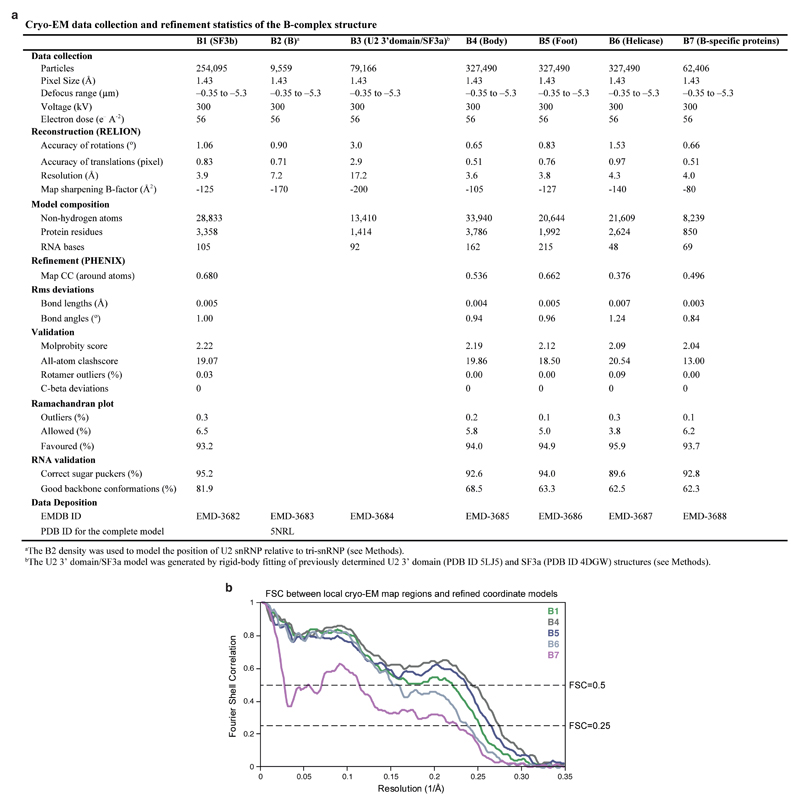
Extended Data Figure 9. Data collection, refinement statistics, and structure validation.
a, Cryo-EM data collection and refinement statistics of the B complex structure. Different regions of the composite B complex structure were refined into B1, B4, B5, B6, and B7 maps as described (see Methods). b, FSC between local cryo-EM map regions and corresponding regions of the refined coordinate models. Note that the FSC curve for the B-specific proteins correlates with the local resolution in this subregion of the B7 density (4.0-5Å, Extended Data Fig. 3d), below the nominal resolution (4.0 Å).
Extended Data Table 1. Summary of components modelled into B complex cryo-EM densities.
| Proteins and RNA included in the model | |||||||||
|---|---|---|---|---|---|---|---|---|---|
| Sub-complexes | Protein/RNA | Domains | Total residues | M.W. (kDa) | Modelled residues | Modelling template (PDB ID) | Modelling | Chain ID | Human/S. pombe names |
| U5 snRNP | Prp8 | N-terminal | 1-870 | 101.7 | 128-870 | 5GAN, 3JCM | Docked and rebuilt | A | U5-220K/Spp42 |
| Large | 871-1827 | 111.5 | 871-1827 | 5GAN, 3JCM | Docked and rebuilt | ||||
| RNaseH | 1828-2085 | 29.5 | 1828-2085 | 5GAN, 3JCM | Docked and rebuilt | ||||
| Jab1/MPN | 2086-2413 | 36.8 | 2086-2109; 2121-2401 | 5GAN | Docked | ||||
| Brr2 | 2,163 | 246.2 | 447-1712; 1716-1825; 1841-2163 | 5GAN | Docked and rebuilt | B | U5-200K/Brr2 | ||
| Snu114 | 1008 | 114.0 | 105-517; 531-693; 706-725; 742-770; 774-979; 986-1005 | 5GAN, 3JCM | Docked and rebuilt | C | U5-116K/Cwf10 | ||
| Dib1 | 143 | 16.8 | 2-143 | 5GAN | Docked and rebuilt | D | U5-15K/Brr2 | ||
| SmB | 196 | 22.4 | 12-54; 76-102 | 4WZJ | Homology modelled | b | SmB/SmB | ||
| SmD3 | 101 | 11.2 | 4-86 | 4WZJ | Homology modelled | d | SmD3/SmD3 | ||
| SmD1 | 146 | 16.3 | 1-48; 78-109 | 4WZJ | Homology modelled | h | SmD1/SmD1 | ||
| SmD2 | 110 | 12.9 | 17-108 | 4WZJ | Homology modelled | i | SmD2/SmD2 | ||
| SmE | 96 | 9.7 | 10-63; 71-93 | 4WZJ | Homology modelled | e | SmE/SmE | ||
| SmF | 86 | 10.4 | 13-84 | 4WZJ | Homology modelled | f | SmF/SmF | ||
| SmG | 77 | 8.5 | 3-73 | 4WZJ | Homology modelled | g | SmG/SmG | ||
| U5 snRNA-S/-L | 179/214 | 68.8 | 1-53; 62-178 | 5GAN | Docked and de novo | 5 | |||
| U2 snRNP | Msl1 | 111 | 12.8 | 28-111 | 1A9N | Homology modelled | Y | U2-B" | |
| Lea1 | 238 | 27.2 | 1-170 | 1A9N | Homology modelled | W | U2-A' | ||
| SmB | 196 | 22.4 | 12-54; 76-102 | 4WZJ | Homology modelled | s | SmB/SmB | ||
| SmD3 | 101 | 11.2 | 4-85 | 4WZJ | Homology modelled | v | SmD3/SmD3 | ||
| SmD1 | 146 | 16.3 | 1-48; 78-101 | 4WZJ | Homology modelled | t | SmD1/SmD1 | ||
| SmD2 | 110 | 12.9 | 17-108 | 4WZJ | Homology modelled | u | SmD2/SmD2 | ||
| SmE | 96 | 9.7 | 10-63; 71-93 | 4WZJ | Homology modelled | w | SmE/SmE | ||
| SmF | 86 | 10.4 | 12-84 | 4WZJ | Homology modelled | x | SmF/SmF | ||
| SmG | 77 | 8.5 | 2-76 | 4WZJ | Homology modelled | y | SmG/SmG | ||
| Hsh155 | 971 | 110.0 | 132-149; 157-971 | 5GM6 | Docked and rebuilt | O | SF3B1/Sap155 | ||
| Rse1 | 1361 | 153.8 | 53-305; 323-571; 581-784; 814-890; 918-1265; 1292-1361 | 5GM6 | Docked and rebuilt | P | SF3B3/Sap130 | ||
| Cus1 | 436 | 50.3 | 125-213; 239-353; 361-376 | 5GM6 | Docked and rebuilt | Q | SF3B2/Sap145 | ||
| Hsh49 | 213 | 24.5 | 9-86; 106-144; 147-185; 189-203 | 5GM6 | Docked and rebuilt | R | SF3B4/Sap49 | ||
| Rds3 | 107 | 12.3 | 2-104 | 5GM6 | Docked and rebuilt | S | SF3B14b/Ini1 | ||
| Ysf3 | 85 | 10.0 | 2-84 | 5GM6 | Docked and rebuilt | Z | SF3B5/Sab10 | ||
| Prp9 | 530 | 63.0 | 1-97; 112-378; 407-478; 503-528 | 4DGW | Docked and de novo | T | SF3A3/Sap61 | ||
| Prp11 | 266 | 29.9 | 34-47; 51-105; 115-136; 149-253 | 4DGW, 5GM6 | Docked and de novo | U | SF3A2/Sap62 | ||
| Prp21 | 280 | 33.1 | 89-206; 220-228 | 4DGW | Docked | V | SF3A1/Sap114 | ||
| U2 snRNA | 1175 | 363.8 | 3-13; 30-73; 79-86; 108-122; 139-150; 1089-1109; 1115-1130; 1138-1154; 1159-1169 | 5LJ5, 5GM6 | Docked and de novo | 2 | |||
| U4/U6 di-snRNP | Snu13 | 126 | 13.6 | 3-126 | 5GAN, 3JCM | Docked and rebuilt | K | U4/U6.U5-15.5K/Snu13 | |
| Prp31 | 494 | 56.3 | 42-458 | 5GAN, 3JCM | Docked and rebuilt | F | U4/U6.U5-61K/Prp31 | ||
| Prp3 | 469 | 55.9 | 35-71; 83-92; 100-138; 140-173; 211-224; 228-410; 413-467 | 5GAN, 3JCM | Docked and rebuilt | G | U4/U6.U5-90K/Prp3 | ||
| Prp4 | 465 | 52.4 | 23-91; 108-465 | 5GAN, 3JCM | Docked and rebuilt | H | 60K/Rna4 | ||
| SmB | 196 | 22.4 | 12-54; 76-102 | 4WZJ | Homology modelled | k | SmB/SmB | ||
| SmD3 | 101 | 11.2 | 4-85 | 4WZJ | Homology modelled | n | SmD3/SmD3 | ||
| SmD1 | 146 | 16.3 | 1-48; 78-119; 138-146 | 4WZJ | Homology modelled | I | SmD1/SmD1 | ||
| SmD2 | 110 | 12.9 | 17-108 | 4WZJ | Homology modelled | m | SmD2/SmD2 | ||
| SmE | 96 | 9.7 | 10-63; 71-93 | 4WZJ | Homology modelled | p | SmE/SmE | ||
| SmF | 86 | 10.4 | 12-84 | 4WZJ | Homology modelled | q | SmF/SmF | ||
| SmG | 77 | 8.5 | 2-76 | 4WZJ | Homology modelled | r | SmG/SmG | ||
| LSm2 | 95 | 11.2 | 1-90 | 4M7A | Docked and rebuilt | a | LSm2/LSm2 | ||
| LSm3 | 89 | 10.0 | 3-79 | 4M7A | Docked | 3 | LSm3/LSm3 | ||
| LSm4 | 172 | 20.3 | 1-47; 64-90 | 4M7A | Docked | j | LSm4/LSm4 | ||
| LSm5 | 93 | 10.4 | 4-54;61-84 | 4M7A | Docked | o | LSm5/LSm5 | ||
| LSm6 | 86 | 9.4 | 11-84 | 4M7A | Docked | z | LSm6/LSm6 | ||
| LSm7 | 115 | 13.0 | 26-70; 85-105 | 4M7A | Docked | 7 | LSm7/LSm7 | ||
| LSm8 | 109 | 12.4 | 4-67 | 4M7A | Docked | 8 | LSm8/LSm8 | ||
| U4 snRNA | 160 | 51.4 | 1-68; 71-79; 90-102; 131-154 | 5GAN | Docked and rebuilt | 4 | |||
| U6 snRNA | 112 | 36.1 | 1-9; 16-51; 55-88; 92-102; 108-112 | 5GAN | Docked and de novo | 6 | |||
| tri-snRNP | Prp6 | 899 | 104.2 | 4-26; 64-80; 98-178; 212-526; 530-896 | 5GAN, 3JCM | Docked and rebuilt | J | PRPF6/Prp7 | |
| Snu66 | 587 | 66.4 | 148-152; 159-223; 232-236; 297-323; 343-364 | De novo | E | U5-102k/Snu66 | |||
| B complex proteins | Snu23 | 194 | 22.7 | 11-19; 33-62; 71-118; 125-146 | 5F5V | Homology modelled and de novo | L | ZMAT2/Snu23 | |
| Prp38 | 242 | 28.0 | 2-64; 74-79; 83-133; 144-169; 182-209 | 5F5V | Homology modelled and de novo | M | hPrp38/Prp38 | ||
| Spp381 | 291 | 33.8 | 98-108; 124-151; 164-173; 181-216 | 5F5V | Homology modelled and de novo | N | MFAP1/Saf3 | ||
| Substrate | UBC4 pre-mRNA | 135 | 40.6 | 6-8; 51-53; 57-79 | Docked and de novo | I | |||
| Unknown | 1-18; 101-111 | de novo | X | ||||||
Supplementary Material
Supplementary Information containing one supplementary movie and a PyMol session is available in the online version of the paper.
Acknowledgements
We thank C. Savva, S. Chen, G. Cannone, K. R. Vinothkumar, G. McMullan, J. Grimmett and T. Darling for maintaining EM and computing facilities; the mass spectrometry facility for protein identification, and A. Newman, L. Strittmatter, S. Fica, M. Wilkinson, and C. Norman for help and critical reading of the manuscript. We thank J. Löwe, V. Ramakrishnan, D. Barford and R. Henderson for their continuing support. The project was supported by the Medical Research Council (MC_U105184330) and European Research Council Advanced Grant (693087 - SPLICE3D). C.P. was supported by an EMBO Long Term Fellowship.
Footnotes
Author contributions
C.P. established complex preparation. C.P. and P.-C.L. carried out cryo-EM structure determination and model building. C.P. refined the model. C.P., P.-C.L., and K.N. analysed the structure and wrote the manuscript. K.N. initiated and supervised the project.
The authors declare no competing financial interests.
Author information
Reprints and permissions information is available at www.nature.com/reprints. Readers are welcome to comment on the online version of the paper.
Data availability
Three-dimensional cryo-EM density maps B1, B2, B3, B4, B5, B6, B7 have been deposited in the Electron Microscopy Data Bank under the accession numbers EMD-3682, EMD-3683, EMD-3684, EMD-3685, EMD-3686, EMD-3687, and EMD-3688, respectively. The coordinate file of B complex has been deposited in the Protein Data Bank under the accession number 5NRL.
References
- 1.Will CL, Lührmann R. Spliceosome structure and function. Cold Spring Harb Perspect Biol. 2011;3:a003707. doi: 10.1101/cshperspect.a003707. [DOI] [PMC free article] [PubMed] [Google Scholar]
- 2.Boesler C, et al. A spliceosome intermediate with loosely associated tri-snRNP accumulates in the absence of Prp28 ATPase activity. Nat Commun. 2016;7:11997. doi: 10.1038/ncomms11997. [DOI] [PMC free article] [PubMed] [Google Scholar]
- 3.Staley JP, Guthrie C. An RNA switch at the 5′ splice site requires ATP and the DEAD box protein Prp28p. Mol Cell. 1999;3:55–64. doi: 10.1016/s1097-2765(00)80174-4. [DOI] [PubMed] [Google Scholar]
- 4.Lesser CF, Guthrie C. Mutations in U6 snRNA that alter splice site specificity: implications for the active site. Science. 1993;262:1982–1988. doi: 10.1126/science.8266093. [DOI] [PubMed] [Google Scholar]
- 5.Lybarger S, et al. Elevated levels of a U4/U6.U5 snRNP-associated protein, Spp381p, rescue a mutant defective in spliceosome maturation. Mol Cell Biol. 1999;19:577–584. doi: 10.1128/mcb.19.1.577. [DOI] [PMC free article] [PubMed] [Google Scholar]
- 6.Stevens SW, Abelson J. Purification of the yeast U4/U6⋅U5 small nuclear ribonucleoprotein particle and identification of its proteins. Proc Natl Acad Sci USA. 1999;96:7226–7231. doi: 10.1073/pnas.96.13.7226. [DOI] [PMC free article] [PubMed] [Google Scholar]
- 7.Laggerbauer B, Achsel T, Lührmann R. The human U5-200kD DEXH-box protein unwinds U4/U6 RNA duplices in vitro. Proc Natl Acad Sci USA. 1998;95:4188–4192. doi: 10.1073/pnas.95.8.4188. [DOI] [PMC free article] [PubMed] [Google Scholar]
- 8.Raghunathan PL, Guthrie C. RNA unwinding in U4/U6 snRNPs requires ATP hydrolysis and the DEIH-box splicing factor Brr2. Curr Biol. 1998;8:847–855. doi: 10.1016/s0960-9822(07)00345-4. [DOI] [PubMed] [Google Scholar]
- 9.Fabrizio P, et al. The evolutionarily conserved core design of the catalytic activation step of the yeast spliceosome. Mol Cell. 2009;36:593–608. doi: 10.1016/j.molcel.2009.09.040. [DOI] [PubMed] [Google Scholar]
- 10.Bessonov S, et al. Characterization of purified human B(act) spliceosomal complexes reveals compositional and morphological changes during spliceosome activation and first step catalysis. RNA. 2010;16:2384–2403. doi: 10.1261/rna.2456210. [DOI] [PMC free article] [PubMed] [Google Scholar]
- 11.Tarn WY, et al. Functional association of essential splicing factor(s) with PRP19 in a protein complex. EMBO J. 1994;13:2421–2431. doi: 10.1002/j.1460-2075.1994.tb06527.x. [DOI] [PMC free article] [PubMed] [Google Scholar]
- 12.Hoskins AA, Rodgers ML, Friedman LJ, Gelles J, Moore MJ. Single molecule analysis reveals reversible and irreversible steps during spliceosome activation. eLife. 2016;5:e14166. doi: 10.7554/eLife.14166. [DOI] [PMC free article] [PubMed] [Google Scholar]
- 13.Madhani HD, Guthrie C. A novel base-pairing interaction between U2 and U6 snRNAs suggests a mechanism for the catalytic activation of the spliceosome. Cell. 1992;71:803–817. doi: 10.1016/0092-8674(92)90556-r. [DOI] [PubMed] [Google Scholar]
- 14.Steitz T, Steitz J. A general two-metal-ion mechanism for catalytic RNA. Proc Natl Acad Sci USA. 1993;90:6498–6502. doi: 10.1073/pnas.90.14.6498. [DOI] [PMC free article] [PubMed] [Google Scholar]
- 15.Fica SM, et al. RNA catalyses nuclear pre-mRNA splicing. Nature. 2013;503:229–234. doi: 10.1038/nature12734. [DOI] [PMC free article] [PubMed] [Google Scholar]
- 16.Newman AJ, Norman C. U5 snRNA interacts with exon sequences at 5′ and 3′ splice sites. Cell. 1992;68:743–754. doi: 10.1016/0092-8674(92)90149-7. [DOI] [PubMed] [Google Scholar]
- 17.Sontheimer E, Steitz J. The U5 and U6 small nuclear RNAs as active site components of the spliceosome. Science. 1993;262:1989–1996. doi: 10.1126/science.8266094. [DOI] [PubMed] [Google Scholar]
- 18.Galej WP, et al. CryoEM structure of the spliceosome immediately after branching. Nature. 2016;537:197–201. doi: 10.1038/nature19316. [DOI] [PMC free article] [PubMed] [Google Scholar]
- 19.Wan R, Yan C, Bai R, Huang G, Shi Y. Structure of a yeast catalytic step I spliceosome at 3.4 Å resolution. Science. 2016;353:895–904. doi: 10.1126/science.aag2235. [DOI] [PubMed] [Google Scholar]
- 20.Rauhut R, et al. Molecular architecture of the Saccharomyces cerevisiae activated spliceosome. Science. 2016;353:1399–1405. doi: 10.1126/science.aag1906. [DOI] [PubMed] [Google Scholar]
- 21.Yan C, Wan R, Bai R, Huang G, Shi Y. Structure of a yeast activated spliceosome at 3.5 Å resolution. Science. 2016;353:904–911. doi: 10.1126/science.aag0291. [DOI] [PubMed] [Google Scholar]
- 22.Yan C, Wan R, Bai R, Huang G, Shi Y. Structure of a yeast step II catalytically activated spliceosome. Science. 2017;355:149–155. doi: 10.1126/science.aak9979. [DOI] [PubMed] [Google Scholar]
- 23.Fica SM, et al. Structure of a spliceosome remodelled for exon ligation. Nature. 2017;542:377–380. doi: 10.1038/nature21078. [DOI] [PMC free article] [PubMed] [Google Scholar]
- 24.Bertram K, et al. Cryo-EM structure of a human spliceosome activated for step 2 of splicing. Nature. 2017;542:318–323. doi: 10.1038/nature21079. [DOI] [PubMed] [Google Scholar]
- 25.Agafonov DE, et al. Molecular architecture of the human U4/U6.U5 tri-snRNP. Science. 2016;351:1416–1420. doi: 10.1126/science.aad2085. [DOI] [PubMed] [Google Scholar]
- 26.Wan R, et al. The 3.8 Å structure of the U4/U6.U5 tri-snRNP: Insights into spliceosome assembly and catalysis. Science. 2016;351:466–475. doi: 10.1126/science.aad6466. [DOI] [PubMed] [Google Scholar]
- 27.Nguyen THD, et al. CryoEM structure of the yeast U4/U6.U5 tri-snRNP at 3.7 Å resolution. Nature. 2016;530:298–302. doi: 10.1038/nature16940. [DOI] [PMC free article] [PubMed] [Google Scholar]
- 28.van Roon A-MM, et al. Crystal structure of U2 snRNP SF3b components: Hsh49p in complex with Cus1p binding domain. RNA. 2017 doi: 10.1261/rna.059378.116. [DOI] [PMC free article] [PubMed] [Google Scholar]
- 29.Lin P-C, Xu R-M. Structure and assembly of the SF3a splicing factor complex of U2 snRNP. EMBO J. 2012;31:1579–1590. doi: 10.1038/emboj.2012.7. [DOI] [PMC free article] [PubMed] [Google Scholar]
- 30.Cretu C, et al. Molecular Architecture of SF3b and structural consequences of its cancer-related mutations. Mol Cell. 2016;64:307–319. doi: 10.1016/j.molcel.2016.08.036. [DOI] [PubMed] [Google Scholar]
- 31.Rigo N, Sun C, Fabrizio P, Kastner B, Lührmann R. Protein localisation by electron microscopy reveals the architecture of the yeast spliceosomal B complex. EMBO J. 2015;34:3059–3073. doi: 10.15252/embj.201592022. [DOI] [PMC free article] [PubMed] [Google Scholar]
- 32.Boehringer D, et al. Three-dimensional structure of a pre-catalytic human spliceosomal complex B. Nat Struct Mol Biol. 2004;11:463–468. doi: 10.1038/nsmb761. [DOI] [PubMed] [Google Scholar]
- 33.Deckert J, et al. Protein composition and electron microscopy structure of affinity-purified human spliceosomal B complexes isolated under physiological conditions. Mol Cell Biol. 2006;26:5528–5543. doi: 10.1128/MCB.00582-06. [DOI] [PMC free article] [PubMed] [Google Scholar]
- 34.Tarn W-Y, Lee K-R, Cheng SC. Yeast precursor mRNA processing protein PRP19 associates with the spliceosome concomitant with or just after dissociation of U4 small nuclear RNA. Proc Natl Acad Sci USA. 1993;90:10821–10825. doi: 10.1073/pnas.90.22.10821. [DOI] [PMC free article] [PubMed] [Google Scholar]
- 35.Wolf E, et al. Exon, intron and splice site locations in the spliceosomal B complex. EMBO J. 2009;28:2283–2292. doi: 10.1038/emboj.2009.171. [DOI] [PMC free article] [PubMed] [Google Scholar]
- 36.Krämer A, Grüter P, Gröning K, Kastner B. Combined biochemical and electron microscopic analyses reveal the architecture of the mammalian U2 snRNP. J Cell Biol. 1999;145:1355–1368. doi: 10.1083/jcb.145.7.1355. [DOI] [PMC free article] [PubMed] [Google Scholar]
- 37.Nesic D, Krämer A. Domains in human splicing factors SF3a60 and SF3a66 required for binding to SF3a120, assembly of the 17S U2 snRNP, and prespliceosome formation. Mol Cell Biol. 2001;21:6406–6417. doi: 10.1128/MCB.21.19.6406-6417.2001. [DOI] [PMC free article] [PubMed] [Google Scholar]
- 38.Igel H, Wells S, Perriman R, Ares M. Conservation of structure and subunit interactions in yeast homologues of splicing factor 3b (SF3b) subunits. RNA. 1998;4:1–10. [PMC free article] [PubMed] [Google Scholar]
- 39.Pauling MH, McPheeters DS, Ares M. Functional Cus1p is found with Hsh155p in a multiprotein splicing factor associated with U2 snRNA. Mol Cell Biol. 2000;20:2176–2185. doi: 10.1128/mcb.20.6.2176-2185.2000. [DOI] [PMC free article] [PubMed] [Google Scholar]
- 40.Dybkov O, et al. U2 snRNA-protein contacts in purified human 17S U2 snRNPs and in spliceosomal A and B complexes. Mol Cell Biol. 2006;26:2803–2816. doi: 10.1128/MCB.26.7.2803-2816.2006. [DOI] [PMC free article] [PubMed] [Google Scholar]
- 41.Schneider C, et al. Dynamic contacts of U2, RES, Cwc25, Prp8 and Prp45 proteins with the pre-mRNA branch-site and 3' splice site during catalytic activation and step 1 catalysis in yeast spliceosomes. PLoS Genet. 2015;11:e1005539. doi: 10.1371/journal.pgen.1005539. [DOI] [PMC free article] [PubMed] [Google Scholar]
- 42.Xie J, Beickman K, Otte E, Rymond BC. Progression through the spliceosome cycle requires Prp38p function for U4/U6 snRNA dissociation. EMBO J. 1998;17:2938–2946. doi: 10.1093/emboj/17.10.2938. [DOI] [PMC free article] [PubMed] [Google Scholar]
- 43.Stevens SW, et al. Biochemical and genetic analyses of the U5, U6, and U4/U6 x U5 small nuclear ribonucleoproteins from Saccharomyces cerevisiae. RNA. 2001;7:1543–1553. [PMC free article] [PubMed] [Google Scholar]
- 44.Agafonov DE, et al. Semiquantitative proteomic analysis of the human spliceosome via a novel two-dimensional gel electrophoresis method. Mol Cell Biol. 2011;31:2667–2682. doi: 10.1128/MCB.05266-11. [DOI] [PMC free article] [PubMed] [Google Scholar]
- 45.Gottschalk A, et al. Identification by mass spectrometry and functional analysis of novel proteins of the yeast [U4/U6.U5] tri-snRNP. EMBO J. 1999;18:4535–4548. doi: 10.1093/emboj/18.16.4535. [DOI] [PMC free article] [PubMed] [Google Scholar]
- 46.Ulrich AKC, Seeger M, Schütze T, Bartlick N, Wahl MC. Scaffolding in the spliceosome via single α helices. Structure. 2016;24:1972–1983. doi: 10.1016/j.str.2016.09.007. [DOI] [PubMed] [Google Scholar]
- 47.Kuhn AN, Li Z, Brow DA. Splicing factor Prp8 governs U4/U6 RNA unwinding during activation of the spliceosome. Mol Cell. 1999;3:65–75. doi: 10.1016/s1097-2765(00)80175-6. [DOI] [PubMed] [Google Scholar]
- 48.Chan S-P, Cheng S-C. The Prp19-associated complex is required for specifying interactions of U5 and U6 with pre-mRNA during spliceosome activation. J Biol Chem. 2005;280:31190–31199. doi: 10.1074/jbc.M505060200. [DOI] [PubMed] [Google Scholar]
- 49.Fica SM, Mefford MA, Piccirilli JA, Staley JP. Evidence for a group II intron-like catalytic triplex in the spliceosome. Nat Struct Mol Biol. 2014;21:464–471. doi: 10.1038/nsmb.2815. [DOI] [PMC free article] [PubMed] [Google Scholar]
- 50.Shuster EO, Guthrie C. Two conserved domains of yeast U2 snRNA are separated by 945 nonessential nucleotides. Cell. 1988;55:41–48. doi: 10.1016/0092-8674(88)90007-4. [DOI] [PubMed] [Google Scholar]
- 51.Nguyen THD, et al. The architecture of the spliceosomal U4/U6.U5 tri-snRNP. Nature. 2015;523:47–52. doi: 10.1038/nature14548. [DOI] [PMC free article] [PubMed] [Google Scholar]
- 52.Umen JG, Guthrie C. A novel role for a U5 snRNP protein in 3' splice site selection. Genes Dev. 1995;9:855–868. doi: 10.1101/gad.9.7.855. [DOI] [PubMed] [Google Scholar]
- 53.Abelson J, Hadjivassiliou H, Guthrie C. Preparation of fluorescent pre-mRNA substrates for an smFRET study of pre-mRNA splicing in yeast. Methods Enzymol. 2010;472:31–40. doi: 10.1016/S0076-6879(10)72017-6. [DOI] [PubMed] [Google Scholar]
- 54.Wu TP, Ruan KC, Liu WY. A fluorescence-labeling method for sequencing small RNA on polyacrylamide gel. Nucleic Acids Res. 1996;24:3472–3473. doi: 10.1093/nar/24.17.3472. [DOI] [PMC free article] [PubMed] [Google Scholar]
- 55.Zhou Z, Reed R. Purification of functional RNA-protein complexes using MS2-MBP. Curr Protoc Mol Biol. 2001;63:27.3.1–27.3.7. doi: 10.1002/0471142727.mb2703s63. [DOI] [PubMed] [Google Scholar]
- 56.Li X, et al. Electron counting and beam-induced motion correction enable near atomic resolution single particle cryo-EM. Nat Methods. 2013;10:584–590. doi: 10.1038/nmeth.2472. [DOI] [PMC free article] [PubMed] [Google Scholar]
- 57.Rohou A, Grigorieff N. CTFFIND4: Fast and accurate defocus estimation from electron micrographs. J Struct Biol. 2015;192:216–221. doi: 10.1016/j.jsb.2015.08.008. [DOI] [PMC free article] [PubMed] [Google Scholar]
- 58.Scheres SH. RELION: Implementation of a Bayesian approach to cryo-EM structure determination. J Struct Biol. 2012;180:519–530. doi: 10.1016/j.jsb.2012.09.006. [DOI] [PMC free article] [PubMed] [Google Scholar]
- 59.Scheres SHW, Chen S. Prevention of overfitting in cryo-EM structure determination. Nat Methods. 2012;9:853–854. doi: 10.1038/nmeth.2115. [DOI] [PMC free article] [PubMed] [Google Scholar]
- 60.Tang G, et al. EMAN2: An extensible image processing suite for electron microscopy. J Struct Biol. 2007;157:38–46. doi: 10.1016/j.jsb.2006.05.009. [DOI] [PubMed] [Google Scholar]
- 61.Scheres SH. Semi-automated selection of cryo-EM particles in RELION-1.3. J Struct Biol. 2015;189:114–122. doi: 10.1016/j.jsb.2014.11.010. [DOI] [PMC free article] [PubMed] [Google Scholar]
- 62.Pettersen EF, et al. UCSF Chimera—A visualization system for exploratory research and analysis. J Comput Chem. 2004;25:1605–1612. doi: 10.1002/jcc.20084. [DOI] [PubMed] [Google Scholar]
- 63.Bai X-C, Rajendra E, Yang G, Shi Y, Scheres SHW. Sampling the conformational space of the catalytic subunit of human γ-secretase. eLife. 2015;4:e11182. doi: 10.7554/eLife.11182. [DOI] [PMC free article] [PubMed] [Google Scholar]
- 64.Kucukelbir A, Sigworth FJ, Tagare HD. Quantifying the local resolution of cryo-EM density maps. Nat methods. 2014;11:63–65. doi: 10.1038/nmeth.2727. [DOI] [PMC free article] [PubMed] [Google Scholar]
- 65.Emsley P, Cowtan K. Coot: model-building tools for molecular graphics. Acta Crystallogr D. 2004;60:2126–2132. doi: 10.1107/S0907444904019158. [DOI] [PubMed] [Google Scholar]
- 66.Adams PD, et al. PHENIX: a comprehensive Python-based system for macromolecular structure solution. Acta Crystallogr D. 2010;66:213–221. doi: 10.1107/S0907444909052925. [DOI] [PMC free article] [PubMed] [Google Scholar]
- 67.Zhou L, et al. Crystal structures of the Lsm complex bound to the 3' end sequence of U6 small nuclear RNA. Nature. 2014;506:116–120. doi: 10.1038/nature12803. [DOI] [PubMed] [Google Scholar]
- 68.Leung AKW, Nagai K, Li J. Structure of the spliceosomal U4 snRNP core domain and its implication for snRNP biogenesis. Nature. 2011;473:536–539. doi: 10.1038/nature09956. [DOI] [PMC free article] [PubMed] [Google Scholar]
- 69.Webb B, Sali A. Current Protoc in Bioinformatics. Vol. 47. John Wiley & Sons, Inc; 2014. Comparative protein structure modeling using Modeller; pp. 5.6.1–5.6.32. [DOI] [PubMed] [Google Scholar]
- 70.Wriggers W. Conventions and workflows for using Situs. Acta Crystallogr D. 2012;68:344–351. doi: 10.1107/S0907444911049791. [DOI] [PMC free article] [PubMed] [Google Scholar]
- 71.Lorenz R, et al. ViennaRNA Package 2.0. Algorithms Mol Biol. 2011;6:26. doi: 10.1186/1748-7188-6-26. [DOI] [PMC free article] [PubMed] [Google Scholar]
- 72.Popenda M, et al. Automated 3D structure composition for large RNAs. Nucleic Acids Res. 2012;40:e112–e112. doi: 10.1093/nar/gks339. [DOI] [PMC free article] [PubMed] [Google Scholar]
- 73.Mozaffari-Jovin S, et al. Inhibition of RNA helicase Brr2 by the c-terminal tail of the spliceosomal protein Prp8. Science. 2013;341:80–84. doi: 10.1126/science.1237515. [DOI] [PubMed] [Google Scholar]
- 74.McGrail JC, O’Keefe RT. The U1, U2 and U5 snRNAs crosslink to the 5′ exon during yeast pre-mRNA splicing. Nucleic Acids Res. 2008;36:814–825. doi: 10.1093/nar/gkm1098. [DOI] [PMC free article] [PubMed] [Google Scholar]
- 75.Sharma S, Wongpalee SP, Vashisht A, Wohlschlegel JA, Black DL. Stem–loop 4 of U1 snRNA is essential for splicing and interacts with the U2 snRNP-specific SF3A1 protein during spliceosome assembly. Genes Dev. 2014;28:2518–2531. doi: 10.1101/gad.248625.114. [DOI] [PMC free article] [PubMed] [Google Scholar]
- 76.van Nues RW, Beggs JD. Functional contacts with a range of splicing proteins suggest a central role for Brr2p in the dynamic control of the order of events in spliceosomes of Saccharomyces cerevisiae. Genetics. 2001;157:1451–1467. doi: 10.1093/genetics/157.4.1451. [DOI] [PMC free article] [PubMed] [Google Scholar]
Associated Data
This section collects any data citations, data availability statements, or supplementary materials included in this article.


