

Abstract
A variety of natural biological tissues (e.g., skin, ligaments, spider silk, blood vessel) exhibit ‘J-shaped’ stress-strain behavior, thereby combining soft, compliant mechanics and large levels of stretchability, with a natural ‘strain-limiting’ mechanism to prevent damage from excessive strain. Synthetic materials with similar stress-strain behaviors have potential utility in many promising applications, such as tissue engineering (to reproduce the nonlinear mechanical properties of real biological tissues) and biomedical devices (to enable natural, comfortable integration of stretchable electronics with biological tissues/organs). Recent advances in this field encompass developments of novel material/structure concepts, fabrication approaches, and unique device applications. This review highlights five representative strategies, including designs that involve open network, wavy and wrinkled morphoologies, helical layouts, kirigami and origami constructs, and textile formats. Discussions focus on the underlying ideas, the fabrication/assembly routes, and the microstructure-property relationships that are essential for optimization of the desired ‘J-shaped’ stress-strain responses. Demonstration applications provide examples of the use of these designs in deformable electronics and biomedical devices that offer soft, compliant mechanics but with inherent robustness against damage from excessive deformation. We conclude with some perspectives on challenges and opportunities for future research.
Keywords: ‘J-shaped’ stress-strain curve, stretchable electronics, network, wrinkling, helix, kirigami, origami, textile
Graphical abstract
The Review highlights representative material/structure strategies to achieve ‘J-shaped’ stress-strain responses, and introduces their applications in strerchable electronics.
1. Introduction
Significant progress in the development of stretchable electronics1-8 based on inorganic materials enables systems that combine extremely deformable mechanics and high-performance electrical properties. These unconventional technologies have significant commercial potential in biomedicine, either to replace the function of biological tissues/organs (e.g. skin-like prosthesis9-13, biomimetic robots14-17, etc.), or to integrate with biological tissues/organs (such as epidermal electronics18-24, flexible implantable medical instruments25-28, etc.).
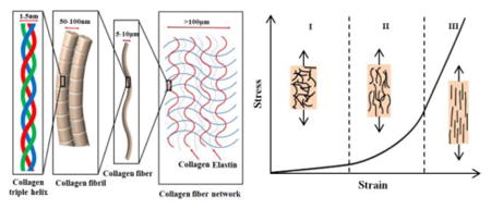
Many biological tissues, such as skin29, 30, ligaments31, spider silk32, 33, blood vessel34, 35, etc., exhibit ‘J-shaped’ stress–strain behaviors36 as depicted in Figure 1a29, as a result of their curved and chained microstructures (e.g., collagen triple helix, collagen fibril, collagen fiber in Figure 1a). This type of stress-strain response is typically characterized by three different stages. In Stage I (Figure 1a), wavy and crimped collagen fibers begin to unfurl by bending and twisting, thereby resulting in a negligible stiffness and compliant mechanics (linear). As the applied strain increases (Stage II), the collagen fibers uncoil, leading to an increase of tangent modulus. After the collagen fibers straighten (Stage III), the stress-strain behavior is dominated by stretching of the fibers, thereby offering relative linear response and high tangent modulus. A goal in the development of engineering materials as substrates or superstrates in stretchable electronics focuses on the development of design that can precisely reproduce the ‘J-shaped’ stress-strain behavior of the real biological tissues.
Figure 1. Microstructures of biological tissues and five representative strategies to enable ‘J-shaped’ stress-strain behavior.
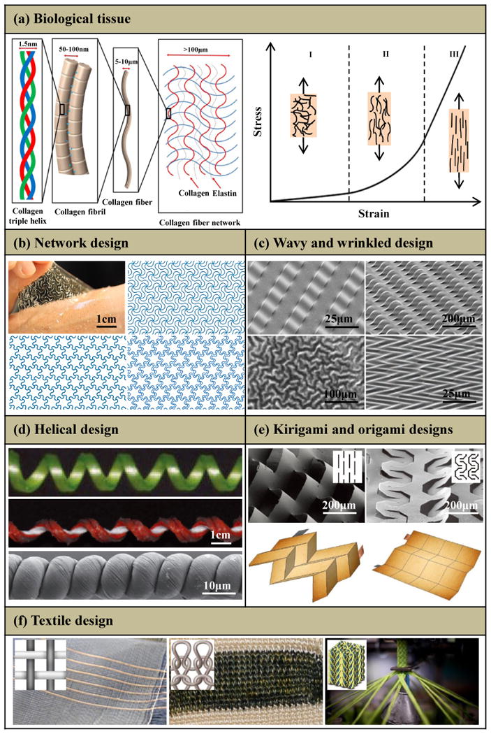
(a) Hierarchical structure of a representative biological tissue spanning the nanoscale dimensions of collagen triple helices to microscale networks of collagen and elastin fibers, and its representative ‘J-shaped’ stress-strain behavior. (b) Network design: optical image (left-top) of a 2D network [triangular (right-top), honeycomb (left-bottom) and Kagome (right-bottom)] embedded in an ultralow-modulus matrix on skin. (c) Wavy and wrinkled design: stiff filamentary ribbons wrinkle on a unidirectionally pre-strained compliant substrate with uniform (left-top) and patterned (right-top) bonding, and stiff films wrinkle on an equi-biaxially (left-bottom) and nonequi-biaxially (right-bottom) pre-strained compliant substrate. (d) Helical design: coiled tendril, silicone fabric ribbon and helical carbon fiber. (e) Kirigami and origami designs: two microscale kirigami patterns in GO-PVA nanocomposites after photolithography (top) and quadrilateral mesh models and two representative Miura origami patterns (bottom). (f) Textile design: weaving (left), knitting (middle) and braiding (right). Panel (a) is adapted with permission from Ref. [29] (Copyright 2015, Nature Publishing Group). Panel (b) is adapted with permission from Ref. [49] (Copyright 2015, Nature Publishing Group). Panel (c) is adapted with permission from Ref. [50] (Copyright 2006, the American Association for the Advancement of Science), Ref. [51] (Copyright 2006, Nature Publishing Group), Ref. [52] (Copyright 2015, John Wiley and Sons) and Ref. [53] (Copyright 2007, American Chemical Society). Panel (d) is adapted with permission from Ref. [54] (Copyright 2012, the American Association for the Advancement of Science) and Ref. [55] (Copyright 2015, Nature Publishing Group). Panel (e) is adapted with permission from Ref. [56] (Copyright 2015, Nature Publishing Group) and Ref. [57] (Copyright 2014, Nature Publishing Group). Panel (f) is adapted with permission from Ref. [58] (Copyright 2017, the American Association for the Advancement of Science) and Ref. [59] (Copyright 2014, MDPI).
To enable natural, comfortable integration of stretchable electronics with biological tissues/organs, an important design consideration is to reduce the stresses induced on the skin by the presence of the devices to within thresholds for somatosensory perception. Specifically, the electronics must be sufficiently compliant to accommodate deformations of soft biological tissues37, 38, typically within several to tens of percent. Materials with ‘J-shaped’ stress-strain behavior are well-matched to this requirement due to their low elastic modulus at small strains39.
In the aforementioned applications, another challenge is in the development of materials/structures strategies to minimize the possibility of mechanically induced device failure40-42. Several design concepts allow stretchable, integrated systems of hard, functional, inorganic components and soft, elastomeric substrate43-48. Here, an emerging design strategy involves the use of a layer with ‘J-shaped’ stress-strain behavior placed between the electronics and the biological tissue. This embedded layer has a high elastic modulus at large strain, to shield the electronics from the potential for large deformations39, 49, thereby providing a so-called “strain-limiting” function.
Figures 1b-f summarize five structural designs that can offer ‘J-shaped’ stress–strain behavior: (i) Network designs49 that adopt wavy, horseshoe microstructures patterned in periodic lattices (e.g., triangular, right-top; honeycomb, left-bottom; Kagome, right-bottom; Fig. 1b); (ii) wavy and wrinkled designs50-53 induced using a pre-strain [unidirectional (top) or bidirectional (bottom) in Fig. 1c] strategy; (iii) helical designs either with natural (e.g., coiled tendril54, in the top of Fig. 1d) or synthetic (e.g, silicone fabric ribbon54 and helical carbon55, in the middle and bottom of Fig. 1d) constructions; (iv) kirigami (in the top of Fig. 1e)56 and origami (in the bottom of Fig. 1e)57 designs that exploiting pre-defined patterns of cuts and creases; (v) textile designs manufactured by weaving (in the left of Fig. 1f)58, knitting (in the middle of Fig, 1f)58 or braiding (in the right of Fig. 1f)59 to yield fabrics. Sections 2-6 summarize each design strategy, highlighting the fundamental principles as well as the key parameters that govern the ‘J-shaped’ stress–strain behavior. A brief discussion of the challenges and prospects for the further study is presented in Section 7.
2. Network design
Curved and chained microstructures in biological tissues (e.g., collagen fiber network in Figure 1a) consist of cross-linked fiber networks with random distributions60-62 that can be reproduced, at some level, in synthetic materials by various approaches (e.g., ionic liquid grinding63, 64, two-step shearing65, plasma-induced modification66 and two-step polymerization67). Ban et al.68 adopted a numerical approach to study the effect of fiber crimp on the stiffness of random fiber networks. To simulate the crimp, a fraction f of the total fibers are assumed to have a sinusoidal form with wavelength 2l and amplitude cl [i.e., x2 = cl sin(πx1/l), as shown in Figure 2a]. The other fibers are straight with length l. Figure 2b shows that the normalized modulus stiffness [Eelastic/E0, where Eelastic (f,c) is the elastic modulus at infinitesimal strain. E0 = Eelastic (f,0)] decreases as f and c increase, indicating that the crimper fibers lead to a reduction of modulus. As the applied stress (σ) increases, the tangent modulus increases (Figure 2c), due to the transition of deformations in the fibers from bending to stretching dominated mode. Jungebluth et al.69 used electrospun synthetic fibers as an artificial scaffolds, and then introduced cells to produce an tissue-engineered rat trachea (Figure 2e) with microstructures and mechanical properties similar to those of native tissues (Figure 2d). The percolation networks based on metal nanowire70, 71, graphene flakes72-74 and carbon nanotubes75, 76 have high conductivity, transmittance and magnetic response, and also can achieve the ‘J-shaped’ stress-strain behavior. The low modulus stages of such percolation networks due to the ‘J-shaped’ stress-strain behavior, together with their own physical characteristics are well-matched with the demands of bio-integrated electronics.
Figure 2. Random network design.
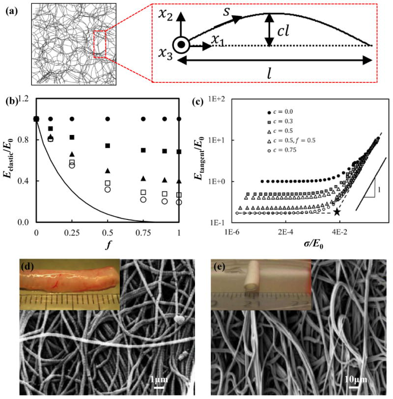
(a) Snapshot of an undeformed random network (f=1 and c=0.2) and schematic diagram of an individual crimped fiber. (b) Normalized network stiffness versus fraction of crimped fibers (f) with c=0 (filled circles), 0.25 (filled squares), 0.5 (triangles), 0.66 (open squares), and 1 (open circles). The solid curve represents the lower bound of the normalized modulus stiffness (Eelastic/E0). (c) Normalized tangent stiffness versus normalized true stress with f=1 for all cases, except for that indicated in the legend. (d, e) SEM images of (d) native rat trachea and (e) electrospun artificial trachea (macroscopic view shown in inset figure). Panels (a), (b) and (c) are adapted with permission from Ref. [68] (Copyright 2016, ASME). Panels (d) and (e) are adapted with permission from Ref. [69] (Copyright 2014, Nature Publishing Group).
Recent work establishes deterministic and bio-inspired design principles based on a two-dimensional (2D) wavy filamentary network embedded in an ultralow-modulus matrix. Here, the ‘J-shaped’ stress-strain behavior can be controlled, through careful choices in geometry, to precisely match those of human skin, as supported by finite element analyses (FEA) and experiment. Specifically, filamentary networks adopt a hierarchical construction of lattice topologies77-83 with horseshoe microstructures46, 84-88, as shown in Figure 1b49. These microscale features can be formed in a variety of materials (e.g, photodefinable polymers, metals and semiconductors) using lithographic approaches. Ma et al.89 introduced a finite deformation model for the horseshoe microstructures (inset, Figure 3a) to predict the nonlinear stress-strain responses. Figures 3a and b89 show normalized stresses (σ/Ematerial) as a function of applied strain, where σ is the effective stress of the horseshoe microstructure, and Ematerial is the elastic modulus of the solid material. The resulting ‘J-shaped’ stress–strain behavior depends on two normalized parameters, the normalized width (w̄ = w/R0) and the arc angle (θ0). As the normalized width (w̄) decreases, the transition of the ‘J-shaped’ stress-strain behavior becomes sharper, as shown in Figure 3a. The critical strain for the transition between low and high modulus regimes is approximately εcr = θ0/[2 sin (θ0/2)]−1, as marked by the dashed line in Figures 3a and b. A large arc angle (θ0) gives a large critical strain, consistent with the results in Figure 3b. As shown in Figures 3c and d, the triangular lattice network (inset, Figure 3c) maintains the ‘J-shaped’ stress-strain behavior of the horseshoe microstructures89. Four key parameters, the elastic modulus, transition strain, peak tangent modulus and peak strain, characterize the ‘J-shaped’ stress-strain curves of the lattice network. Quantitative mechanics models offer accurate predictions of these parameters as well as the deformed configurations89. Fractal designs90 provide routes to strain-limiting materials with improved stretchabilities and multiple transition points during stretching. Figure 3e shows the normalized stresses (in logarithmic scale) versus applied strain for first-, second- and third-order fractal horseshoe microstructures, respectively, with fixed arc angle (θ0=240°), normalized width (w̄=0.2) and 8 unit cells for each order. In addition, the high-order (e.g., > 2) fractal horseshoe microstructures have a substantially reduced elastic modulus, as compared to traditional, first-order horseshoe designs. This result is advantageous for strain-limiting materials in bio-integrated applications, due to reduced levels of induced stresses.
Figure 3. Deterministic network design.
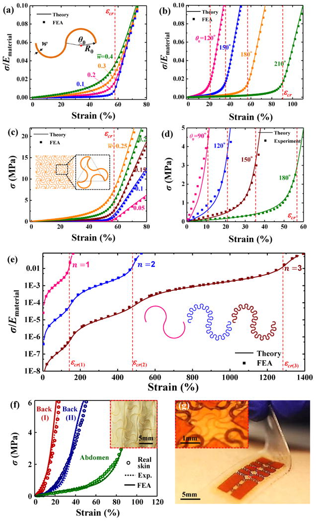
Normalized stress-strain relation for a horseshoe microstructure with (a) fixed arc angle (θ0=180°) and several normalized width (w̄), and (b) fixed normalized width (w̄=0.2) & several arc angle (θ0). Stress-strain relation for a network design based on hierarchical triangular lattice consisting of horseshoe microstructures with (c) fixed arc angle (θ0=180°) & several normalized width (w̄), and (d) fixed normalized width (w̄=0.15) & several arc angle (θ0). (e) Stress-strain relation for the first-, second- and third-order fractal horseshoe microstructures, respectively, with the fixed arc angle (θ0=240°), normalized width (w̄=0.2) and 8 unit cells for each order. (f) Stress–strain responses of human skin and artificial skin for various locations on different individuals (inset figure: optical images of artificial skin). (g) Optical image of a core/shell structure with electronics that includes a strain-limiting layer in the form of a wave filamentary network of polyimide. Panels (a), (b), (c) and (d) are adapted with permission from Ref. [89] (Copyright 2016, Elsevier). Panel (e) is adapted with permission from Ref. [90] (Copyright 2016, ASME). Panel (f) is adapted with permission from Ref. [49] (Copyright 2015, Nature Publishing Group). Panel (g) is adapted with permission from Ref. [37] (Copyright 2015, John Wiley and Sons).
The network design can be implemented in a sandwich construction (Silbione/filamentary network/ Silbione) to match precisely the non-linear stress-strain responses of human skin at different regions (e.g., back and abdomen), as shown in Figure 3f 49. Here, a copper layer was deposited on a glass slide to serve as a sacrificial layer, followed by spin casting of a PI layer onto the top of the copper layer.37 Photolithographic patterning of this PI layer enables formation of a deterministic network that was then transfer printed onto the surface of the elastomer, and uniformly coated with another elastomer layer. Transfer printing of the stretchable electronics onto this composite, strain-limiting structure finishes the integration of the entire device system. The strain-limiting effect of such network design can be also utilized to protect the electronics from levels of stretching that could lead to fracture of the electronic materials37, as shown in Figure 3g.
3. Wavy and wrinkled design
For a stiff thin film bonded to a compliant substrate, differences in strain (either by thermally induced mismatch91 or mechanical pre-strain92-95) between the film and substrate can lead to wrinkling of the film into a sinusoidal form (Figure 1c). Figure 4a presents a schematic illustration of a process for fabricating wavy films of PI bonded on to a low modulus silicone substrate (Silbione) 39. At small applied strain, the wrinkled PI film has a negligible stiffness and does not contribute to the tensile stiffness of the system96. The result is a low elastic modulus (Stage I in Figure 4b), with a value that is almost the same as the intrinsic value of the substrate. As the applied strain increases, the wrinkled PI film becomes flat and therefore contributes to the stiffness of the system, yielding a high tangent modulus (Stage II in Figure 4b). As a result, the wrinkled film/substrate structure has a bilinear stress-strain behavior with an extremely sharp transition point, and an exceptionally high ratio of tangent to elastic modulus, which is particularly valuable as a strategy for constructing strain-limiting materials.
Figure 4. Wavy and wrinkled design.
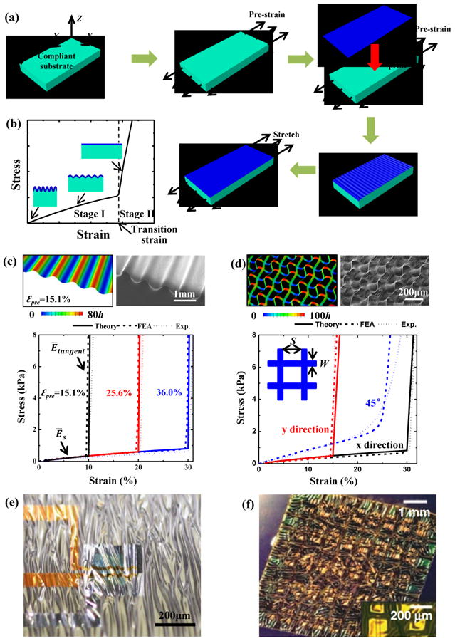
(a) Schematic illustration of the process for fabricating wavy/wrinkled strain-limiting structures. (b) Bilinear stress–strain behavior of the strain-limiting structure. (c) Bilinear stress–strain curves of 1 μm-thick PI film on 1 mm-thick Silbione substrate subjected to various pre-strains, along with its optical morphology and out-of-plane displacement subjected to 15.1% pre-strain. (d) Stress-strain curves for x-, y-, and 45°-stretching of 1 μm-thick PI mesh (width W=0.1mm and spacing S=0.4mm) on 1 mm-thick Silbione substrate subjected to pre-strains of =30.8% and =15.7%, along with its optical morphology and out-of-plane displacement. (e, f) Optical images of wrinkling electronic films when substrate shrinks caused by (e) pre-strain releasing and (f) temperature change. Panels (a), (b), (c) and (d) are adapted with permission from Ref. [39] (Copyright 2016, John Wiley and Sons). Panel (e) is adapted with permission from Ref. [97] (Copyright 2013, Nature Publishing Group). Panel (f) is adapted with permission from Ref. [98] (Copyright 2008, the American Association for the Advancement of Science).
Release of the pre-strain in the substrate leads to the bending of the system with a curvature κH = 6[9Ēfh3/(ĒsH3)]1/3, when no additional constraints are involved96. If such bending is noticeable, it can be eliminated by adopting additional constraints, e.g., through use of fixture to minimize the rotations of the system at two ends during the release of the pre-strain. When such strain-limiting system sticks onto the target body (e.g., skin), the bending also can be eliminated by applying constraints to the bottom surface of the system.
Substrates with finite thickness no longer recover to their initial length upon release of the pre-strain. The result is a transition strain (εtransition, as shown in Figure 4b) that is not equal to the pre-strain (εpre). Ma et al.39 gives a relation between the transition strain (εtransition) and the pre-strain (εpre) as
| (1) |
where H and h are the thickness of the substrate and film. and are the plane-strain modulus of the substrate and film, respectively, and Es, Ef, vs and vf are the corresponding elastic modulus and Poisson's ratios. In addition to the transition strain, the ratio of the tangent to the elastic modulus also represents an important property, given by Ētangent/Ēelastic ≈ 1 + h Ēf/HĒs)39. Figure 3c shows bilinear stress-strain curves for a 1 μm-thick PI film on a 1 mm-thick Silbione substrate with three different levels of pre-strain39. The transition strains are 10%, 20% and 30%, respectively.
Figure 4d shows a wavy, wrinkled design created by biaxial stretching. The thin film is replaced by a thin mesh (width W and spacing S, Figure 4d) on a biaxially pre-strained ( and ), compliant substrate. The transition strain and ratio of tangent to elastic modulus are given by39
| (2) |
where the superscript i denotes either x or y. Figure 4d shows the stress-strain curves for x-, y- and 45°-stretching of a 1 μm-thick PI mesh on a 1 mm-thick Silbione substrate subjected to the pre-strains and (Ref. 39). The resulting transition strains and are 30% and 15%, respectively.
In addition to ‘J-shaped’ stress–strain behavior, the wavy and wrinkled design also provides a route to stretchability in electronic materials, representing a strategy that has been widely used in many stretchable electronic devices. For example, Kaltenbrunner et al.97 printed an ultrathin electronic polymer foil onto a pre-strained elastomer (Figure 4e), which forms a wrinkled configuration that can accommodate relative large tensile strains. Kim et al.98 fabricated biaxially wavy CMOS (complementary metal–oxide–semiconductor) circuits on a thin polymer film (Figure 4f), through use of biaxial thermal strain in the elastomeric substrate. Both of these examples97, 98 give compliant response at small strain, due to the low elastic modulus. The polymer film becomes stiff when it is stretched flat again, which shields the electronics from high strains.
4. Helical design
Helical microstructures99 also possess the ‘J-shaped’ stress–strain behavior100-104. For a helical ribbon, as shown in Figure 5a, Pham et al.105 gave an analytical expression that captures the non-linear mechanics response under the conditions that the ratio of t/w ≪ 1 and L/w ≪ 1, i.e.,
Figure 5. Helical design.
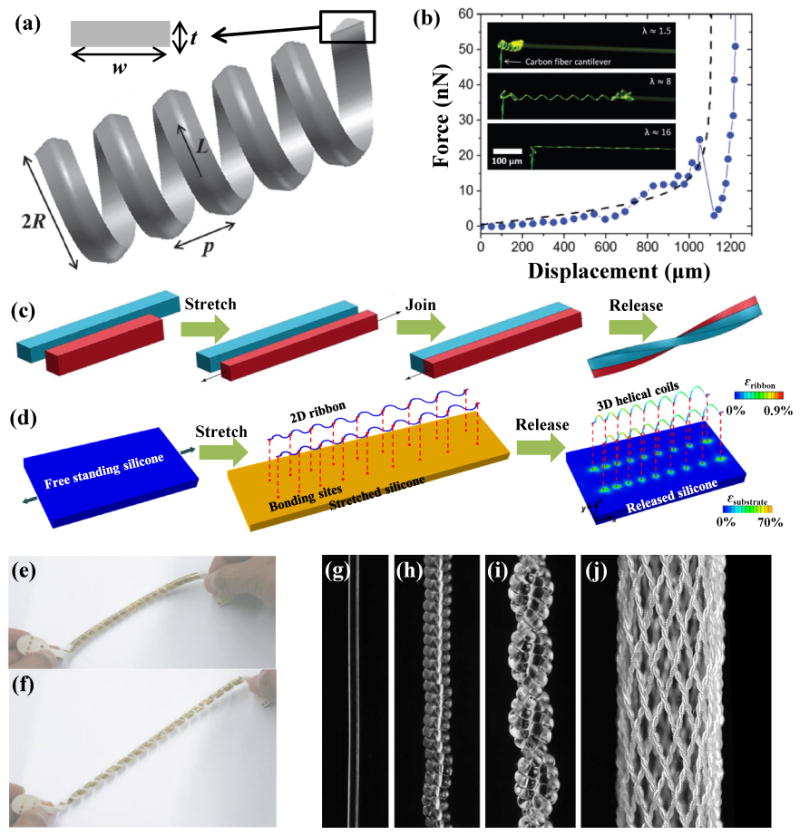
(a) Geometrical illustration of the helical microstructure. (b) Optical image of the stretching process for a helical carbon fiber and its ‘J-shaped’ stress-strain behavior. (c, d) Two alternative approaches to assembly of the 3D helix from 2D structures. (e, f) A thin-film transistor array helix (e) before and (f) after 50% stretching. (g) A 300-mm-diameter nylon 6,6 fiber; (h) a coil fiber; (i) a two-ply fiber formed from (h); (j) a braid formed from 32 two-ply fiber (i). Panels (a) and (b) are adapted with permission from Ref. [105] (Copyright 2014, Royal Society of Chemistry). Panel (c) is adapted with permission from Ref. [110] (Copyright 2014, Public Library of Science). Panel (d) is adapted with permission from Ref. [112] (Copyright 2015, the American Association for the Advancement of Science). Panels (e) and (f) are adapted with permission from Ref. [117] (Copyright 2010, Nature Publishing Group). Panels (g-j) are adapted with permission from Ref. [120] (Copyright 2014, the American Association for the Advancement of Science).
| (3) |
where the geometry is described by the contour length (L = Nl, with l denoting the contour length of a single turn, and N the number of helical turns), pitch (p), radius , width (w) and thickness (t), as illustrated in Figure. 5a. p0 and R0 are the initial pitch and radius. E and v are the elastic modulus and Poisson's ratio of the material, respectively. To verify this analytical solution, Pham et al.105 also carried out experiments on a helical carbon fiber (R0=15μm, L=1190μm, N=12.5, w=5.9μm, t=122nm, E=1.3GPa and v=0.3). The measured force-displacement curves agree well with the analytical solution (Eq. 3), as shown in Figure 5b.
Three-dimensional (3D) printing99 (e.g., fused deposition modeling106, UV-assisted 3D printing107 and solvent-cast 3D printing108) represents one straightforward approach to helical microstructures, but with limited choices in materials. Figure 5c summarizes an alternative strategy that uses mechanical assembly. Specifically, two strips of different lengths are adhered together side-by-side, after stretching the short strip to a length that matches that of the long one. Upon release of the stretch, this bi-strip twists and bends either into a helix or a hemihelix109-111. Recently, Xu et al.112 reported a mechanically-guided approach for assembly of complex, 3D architectures in a diversity of high-performance materials, including semiconductors (e.g, silicon), metals (e.g., Au, Cu, Ni), polymers (e.g., PI, SU8), and their heterogeneous integration. Here, filamentary serpentine ribbons serve as 2D precursors that are bonded to a pre-stretched silicone elastomer at selected points (red dots in Figure 5d). 3D helical microstructures form spontaneously upon release of the pre-strain. This type of 2D-3D geometric transformation follows from a process of compressive buckling that can be analyzed quantitatively using a finite-deformation model113. Similar processes can form coiled nanowires114-116.
By exploiting the compliant nature of the helical structure under small tensile strain, Sekitani et al.117 fabricated a thin-film transistor array on a shape-memory polymer film that was transformed into a helical configuration to shield the electronics from high strains. Figures 5e and f show this helical thin-film transistor array before and after 50% stretching. To mimic the ‘J-shaped’ stress–strain behavior of the muscle118, 119, Haines et al.120 proposed a type of artificial muscle by using the nylon 6,6 coil fibers show in Figures 5g-j.
5. Kirigami and origami designs
Kirigami56, 121-124 is an ancient art of paper cutting and folding to form 3D sculptures. Figure 6a shows a kirigami model in Kent paper (thickness of 0.2-0.3mm and modulus of 2.45-3.27GPa) with regularly arranged cuts (w≃10-30mm and d≃1-5mm), and its force-displacement curve is presented in Figure 6b125. In the initial regime (small applied strain), the elementary plates in Kent paper deform mainly via in-plane buckling, which leads to a linear force-displacement curve as shown in the inset. As the applied strain increases (second regime), out-of-plane buckling occurs, resulting in force reduction of the paper. In the final regime, the elementary plates in Kent paper are straightened, which induces an increase in the stiffness again. In this design, a small thickness126 promotes out-of-plane buckling, and thereby shortens the initial regime. Bahamon et al.127, 128 used molecular dynamics (MD) to calculate the stress-strain curve of kirigami structures in graphene, in which the initial stiff regime almost disappears entirely.
Figure 6. Kirigami and origami designs.
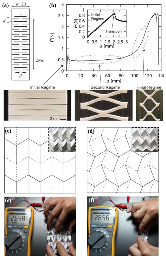
(a) Kirigami pattern in a Kent paper and (b) its force-displacement curve with initial (inset), second and final regimes. Crease mesh and folding morphology for (c) Miura and (d) double corrugation origami. (e) Folding and (f) unfolding status of an origami lithium-ion batteries while it was connected to a voltmeter. Panels (a) and (b) are adapted with permission from Ref. [125] (Copyright 2016, Nature Publishing Group). Panels (c) and (d) are adapted with permission from Ref. [134] (Copyright 2016, The Royal Society). Panels (e) and (f) are adapted with permission from Ref. [57] (Copyright 2014, Nature Publishing Group).
Origami129-133 is an ancient art of paper folding, in which the key is to form pre-defined crease patterns. Figures 6c and d134 show two quadrilateral mesh creases. Folding these ‘mountain’ (solid line) and ‘valley’ (dotted line) creases forms Miura and double corrugation origami (Figures 6c and d, inset). These origami designs possess similar mechanics properties as those of the wavy and wrinkled structures. At a small applied strain, the parallelogram faces experience almost zero strains except at the creases, and the entire system has a very low stiffness. As the applied strain increases, the folding creases straightened, and the parallelogram faces dominate the stretching such that the structure becomes stiff. These deformation mechanisms result in ‘J-shaped’ stress-strain behavior135. Recently, Yan et al.136 proposed a strategy to produce engineered folding creases for microscale origami structures in polymer films, with ‘J-shaped’ stress-strain behaviors. Song et al.57 exploited an origami design with 45° Miura folding for applications in a lithium-ion battery that is highly deformable at different modes (e.g., stretching, folding, bending and twisting). Figures 6e and f show folded and unfolded origami lithium-ion batteries where the output voltages remain almost unchanged (2.65 V) during the deformations.
6. Textile design
Textiles are flexible materials that consist of networks of natural or artificial yarns as shown in Figure 1f. Weaving and knitting58 are the most widely used methods for manufacturing textiles. In the weaving process (Figure 1f, left), perpendicular and individual yarns (warp and weft yarns) interlace together to form the fabric. In the knitting process (Figure 1f, middle), the yarns adopt wavy, looped configurations, with the potential to offer large stretchabilities. Figure 7a gives a schematic diagram of stress-strain responses for a single yarn, a weaved fabric, and a knitted fabric58. The single yarn has a relative linear stress–strain behavior and a large initial modulus. The ‘J-shaped’ stress–strain behavior of the knitted fabric is more significant than that of the weaved fabric, while they both approach the stiffness of the single yarn at high strain. Figure 7b shows the load-displacement curves for samples of cotton knitted fabrics cut at different angles137, displaying a significant anisotropy. The sample cut at 90° direction has the lowest initial stiffness and largest transition strain between low and high stiffness, followed by the 45° and 0° directions. For 3D textile fabrics, braiding (Figure 1f, right) is a widely used method, which forms the textile by inter-plaiting yarns along three orthogonal directions, also with capabilities in offering ‘J-shaped’ stress–strain behavior138. Figure 7c shows stress-strain responses and optical images of a fabric integrated with electronics under stretching139. As for the other cases mentioned previously, the ‘J-shaped’ stress–strain behavior of the fabric maintains compliance of stretchable electronics at small strain, and also eliminates the possibility of failure at large strain140.
Figure 7. Textile design.
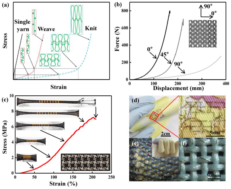
(a) Stress-strain responses of a single yarn, a weaved fabric, and a knitted fabric. (b) Anisotropy of a knitted fabric cut under different angles. (c) Stress-strain response of a fabric integrated with stretchable electronics. (d) An ultrathin IGZO-based 7-stage ring oscillator transferred on a handkerchief. (e) A knitted fabric circuit board on a human finger. (f) Copper wires embedded in yarns to realize a textile circuit. Panel (a) is adapted with permission from Ref. [58] (Copyright 2017, the American Association for the Advancement of Science). Panel (b) is adapted with permission from Ref. [137] (Estonian Academy Publishers). Panel (c) is adapted with permission from Ref. [139] (Copyright 2014, Nature Publishing Group). Panel (d) is adapted with permission from Ref. [141] (Copyright 2016, Nature Publishing Group). Panel (e) is adapted with permission from Ref. [142] (Copyright 2014, The Royal Society). Panel (f) is adapted with permission from Ref. [59] (Copyright 2014, MDPI).
The rough textures of the fabric can create challenges in the transfer of stretchable electronics onto its surface. Yoon et al.141 introduced an artificial cilia structure at the periphery regions of stretchable electronic platforms as adhesive elements to facilitate transfer printing. Using this strategy, an ultrathin layer of indium gallium zinc oxide as the basis of a 7-stage ring oscillator was successfully transferred onto a handkerchief, as shown in Figure 7d. Figures 7e and f show two alternatives approaches for integrating stretchable electronics with fabric: (1) replacing parts of fabric yarns by metal wire (Figure 7e)142; (2) embedding metal wire into fabric yarns (Figure 7f)59.
7. Concluding remarks
Collectively, the advances in materials and mechanics described here provide several promising engineering approaches to materials with ‘J-shaped’ stress–strain behaviors, with potential for applications in tissue engineering and biomedical devices. Table 1 summarizes the characteristic dimensions, fabrication methods and featured performances of these approaches described in this review paper. Nevertheless, there are many opportunities for further work. For example, previous studies on artificial tissues mainly focus on matching the ‘J-shaped’ stress–strain responses of biological tissues in 1D (e.g., muscle fiber and ligament), 2D (e.g., skin) or very simple 3D (e.g., trachea and blood vessel) configurations. Reproduction of nonlinear, multi-axial, mechanical behaviors in complex 3D organs/tissues remains a challenge. Many biological tissues (e.g., ligament) have intrinsic anisotropic mechanical properties and different tension-compression moduli, also representing design challenges in the tissue engineering. In addition to mechanical compatibility with biological tissues, the biocompatibility to avoid the immune response in the tissue engineering is important to consider, which limits the material selections for the artificial tissues. The strain-limiting structures introduced in this paper offer only a capacity to shield stretchable electronics from in-plane tension. Development of structural designs with strain-limiting properties under in-plane compression or out-of-plane pressure by exploiting 3D designs represents an important direction for future research. Furthermore, the thickness and stiffness of the stretchable electronics increase after integration with the strain-limiting structures, which may increase the foreign body sensation of the biological tissues when wearing such stretchable electronics. Optimization of the structural designs to enable reduced thickness and stiffness of the entire integrated device system is an important consideration for future bio-integrated applications. In conclusion, the above opportunities provide strong motivation for continued and expanded efforts in the fields of biomedical devices and stretchable electronics.
Table 1.
Minimum microstructure dimensions, fabrication methods and featured performances of various structural designs to achieve ‘J-shaped’ stress–strain behaviors.
| Design | Minimum microstructure dimension | Fabrication | Featured performance |
|---|---|---|---|
| Random network design | ∼10nm | Ionic liquid grinding63,64, two-step shearing65, plasma-induced modification66, and two-step polymerization67 | Small dimension (Nano scale) |
| Deterministic network design | ∼100μm | Lithographic approach49 | High degree of design flexibility |
| Wavy and wrinkled design | ∼100μm | Thermally induced mismatch91, pre-strain92-95 | Sharp transition point, and high ratio of tangent to elastic modulus |
| Helical design | ∼10μm | 3D printing99, mechanically-guided approach112 | Strain limiting feature only along the axial direction of helices |
| Kirigami and origami designs | ∼10μm | Lithographic approach56, laser cutting122, mechanically-guided approach136 | Transformable between 2D and 3D configurations |
| Textile design | ∼1mm | Weaving58, knitting58, and braiding59 | Mature technology for commercial application |
Acknowledgments
Y.M. and X.F. acknowledge the support from the National Basic Research Program of China (Grant No. 2015CB351900) and National Natural Science Foundation of China (Grant Nos. 11402135 and 11320101001). Y.Z. acknowledges the support from the National Natural Science Foundation of China (Grant No. 11502129). Y.H. acknowledges the support from NSF (Grant Nos. DMR-1121262, CMMI-1300846, CMMI-1400169 and CMMI-1534120) and the NIH (Grant No. R01EB019337).
Biographies

John A. Rogers is the Louis Simpson and Kimberly Querrey Professor of Materials Science and Engineering, Biomedical Engineering, Mechanical Engineering, Electrical Engineering and Computer Science, Chemistry and Neurological Surgery at Northwestern University where he also serves as Director of the Center on Bio-Integrated Electronics. Rogers' research focuses on unusual electronic and photonic devices, with an emphasis on bio-integrated and bio-inspired systems. He has published nearly 600 papers and is a member of the National Academy of Engineering, the National Academy of Sciences and the American Academy of Arts and Sciences.
Xue Feng is a Professor of Engineering Mechanics at Tsinghua University. His research interests include flexible electronics, solid mechanics and experimental mechanics in extreme environments. He is an associate editor of “Journal of Applied Mechanics” (ASME Transactions), and serves on the editorial board of “npj Flexible Electronics” and “Flexible and Printed Electronics”.
Yihui Zhang is an Associate Professor of Engineering Mechanics at Tsinghua University. Before joining Tsinghua, he was a Research Assistant Professor at Northwestern University. His research interests include mechanically guided 3D assembly, bioinspired soft materials, and stretchable electronics. His recent honors and awards include ASME Journal of Applied Mechanics Award (2017), MIT Technology Review's 35 Innovators Under 35 (2016), Qiu Shi Outstanding Young Scholar Award (2016). He is an associate editor of Journal of Applied Mechanics (ASME Transactions), and serves on the editorial board of Proceedings of the Royal Society A, npj Flexible Electronics and Acta Mechanica Solida Sinica.

Yinji Ma is a postdoctoral fellow at the Northwestern University of USA. He received his PhD degree from Tsinghua University of China. His research interests include experimental mechanics, solid mechanics and flexible electronics.

Yonggang Huang is the Walter P. Murphy Professor of Mechanical Engineering, Civil and Environmental Engineering, and Materials Science and Engineering at Northwestern University. He is interested in mechanics of stretchable and flexible electronics, and mechanically guided deterministic 3D assembly. He is a member of the US National Academy of Engineering. His recent research awards (since 2013) include the Drucker Medal in 2013 and Nadai Medal in 2016 from American Society of Mechanical Engineers, and Prager Medal in 2017 from the Society of Engineering Sciences; and Highly Cited Researcher.
References
- 1.Jang KI, Jung HN, Lee JW, Xu S, Liu YH, Ma YJ, Jeong JW, Song YM, Kim J, Kim BH, Badea A, Kwak JW, Yang YY, Shi DW, Wei Z, Feng X, Paik U, Huang Y, Ghaffari R, Rogers JA. Adv Funct Mater. 2016;26:7281–7290. doi: 10.1002/adfm.201603146. [DOI] [PMC free article] [PubMed] [Google Scholar]
- 2.Gao W, Emaminejad S, Nyein HYY, Challa S, Chen KV, Peck A, Fahad HM, Ota H, Shiraki H, Kiriya D, Lien DH, Brooks GA, Davis RW, Javey A. Nature. 2016;529:509–514. doi: 10.1038/nature16521. [DOI] [PMC free article] [PubMed] [Google Scholar]
- 3.Jeong SH, Hagman A, Hjort K, Jobs M, Sundqvist J, Wu ZG. Lab Chip. 2012;12:4657–4664. doi: 10.1039/c2lc40628d. [DOI] [PubMed] [Google Scholar]
- 4.Cheng S, Wu ZG. Lab Chip. 2012;12:2782–2791. doi: 10.1039/c2lc21176a. [DOI] [PubMed] [Google Scholar]
- 5.Ahn BY, Duoss EB, Motala MJ, Guo XY, Park SI, Xiong YJ, Yoon J, Nuzzo RG, Rogers JA, Lewis JA. Science. 2009;323:1590–1593. doi: 10.1126/science.1168375. [DOI] [PubMed] [Google Scholar]
- 6.Yan CY, Lee PS. Small. 2014;10:3443–3460. doi: 10.1002/smll.201302806. [DOI] [PubMed] [Google Scholar]
- 7.Vanfleteren J, Gonzalez M, Bossuyt F, Hsu YY, Vervust T, De Wolf I, Jablonski M. MRS Bull. 2012;37:254–260. [Google Scholar]
- 8.Huyghe B, Rogier H, Vanfleteren J, Axisa F. Ieee T Adv Packaging. 2008;31:802–808. [Google Scholar]
- 9.Kim J, Lee M, Shim HJ, Ghaffari R, Cho HR, Son D, Jung YH, Soh M, Choi C, Jung S, Chu K, Jeon D, Lee ST, Kim JH, Choi SH, Hyeon T, Kim DH. Nat Commun. 2014;5:5747. doi: 10.1038/ncomms6747. [DOI] [PubMed] [Google Scholar]
- 10.Chortos A, Liu J, Bao ZA. Nat Mater. 2016;15:937–950. doi: 10.1038/nmat4671. [DOI] [PubMed] [Google Scholar]
- 11.Muth JT, Vogt DM, Truby RL, Menguc Y, Kolesky DB, Wood RJ, Lewis JA. Adv Mater. 2014;26:6307–6312. doi: 10.1002/adma.201400334. [DOI] [PubMed] [Google Scholar]
- 12.Gerratt AP, Michaud HO, Lacour SP. Adv Funct Mater. 2015;25:2287–2295. [Google Scholar]
- 13.Pang C, Koo JH, Nguyen A, Caves JM, Kim MG, Chortos A, Kim K, Wang PJ, Tok JBH, Bao ZA. Adv Mater. 2015;27:634–640. doi: 10.1002/adma.201403807. [DOI] [PubMed] [Google Scholar]
- 14.Ko HC, Stoykovich MP, Song JZ, Malyarchuk V, Choi WM, Yu CJ, Geddes JB, Xiao JL, Wang SD, Huang YG, Rogers JA. Nature. 2008;454:748–753. doi: 10.1038/nature07113. [DOI] [PubMed] [Google Scholar]
- 15.Song YM, Xie YZ, Malyarchuk V, Xiao JL, Jung I, Choi KJ, Liu ZJ, Park H, Lu CF, Kim RH, Li R, Crozier KB, Huang YG, Rogers JA. Nature. 2013;497:95–99. doi: 10.1038/nature12083. [DOI] [PubMed] [Google Scholar]
- 16.Rus D, Tolley MT. Nature. 2015;521:467–475. doi: 10.1038/nature14543. [DOI] [PubMed] [Google Scholar]
- 17.Lu NS, Kim DH. Soft Robot. 2014;1:53–62. [Google Scholar]
- 18.Kim DH, Lu NS, Ma R, Kim YS, Kim RH, Wang SD, Wu J, Won SM, Tao H, Islam A, Yu KJ, Kim TI, Chowdhury R, Ying M, Xu LZ, Li M, Chung HJ, Keum H, McCormick M, Liu P, Zhang YW, Omenetto FG, Huang YG, Coleman T, Rogers JA. Science. 2011;333:838–843. doi: 10.1126/science.1206157. [DOI] [PubMed] [Google Scholar]
- 19.Webb RC, Ma Y, Krishnan S, Li Y, Yoon S, Guo X, Feng X, Shi Y, Seidel M, Cho NH, Kurniawan J, Ahad J, Sheth N, Kim J, Taylor JG, VI, Darlington T, Chang K, Huang W, Ayers J, Gruebele A, Pielak RM, Slepian MJ, Huang Y, Gorbach AM, Rogers JA. Sci Adv. 2015;1:e1500701. doi: 10.1126/sciadv.1500701. [DOI] [PMC free article] [PubMed] [Google Scholar]
- 20.Benight SJ, Wang C, Tok JBH, Bao ZA. Prog Polym Sci. 2013;38:1961–1977. [Google Scholar]
- 21.Someya T, Sekitani T, Iba S, Kato Y, Kawaguchi H, Sakurai T. Proc Natl Acad Sci USA. 2004;101:9966–9970. doi: 10.1073/pnas.0401918101. [DOI] [PMC free article] [PubMed] [Google Scholar]
- 22.Son D, Lee J, Qiao S, Ghaffari R, Kim J, Lee JE, Song C, Kim SJ, Lee DJ, Jun SW, Yang S, Park M, Shin J, Do K, Lee M, Kang K, Hwang CS, Lu NS, Hyeon T, Kim DH. Nat Nanotechnol. 2014;9:397–404. doi: 10.1038/nnano.2014.38. [DOI] [PubMed] [Google Scholar]
- 23.Xu S, Zhang YH, Jia L, Mathewson KE, Jang KI, Kim J, Fu HR, Huang X, Chava P, Wang RH, Bhole S, Wang LZ, Na YJ, Guan Y, Flavin M, Han ZS, Huang YG, Rogers JA. Science. 2014;344:70–74. doi: 10.1126/science.1250169. [DOI] [PubMed] [Google Scholar]
- 24.Yang SX, Chen YC, Nicolini L, Pasupathy P, Sacks J, Su B, Yang R, Sanchez D, Chang YF, Wang PL, Schnyer D, Neikirk D, Lu NS. Adv Mater. 2015;27:6423–6430. doi: 10.1002/adma.201502386. [DOI] [PubMed] [Google Scholar]
- 25.Xu LZ, Gutbrod SR, Ma YJ, Petrossians A, Liu YH, Webb RC, Fan JA, Yang ZJ, Xu RX, Whalen JJ, Weiland JD, Huang YG, Efimov IR, Rogers JA. Adv Mater. 2015;27:1731–1737. doi: 10.1002/adma.201405017. [DOI] [PMC free article] [PubMed] [Google Scholar]
- 26.Lu BW, Chen Y, Ou DP, Chen H, Diao LW, Zhang W, Zheng J, Ma WG, Sun LZ, Feng X. Sci Rep. 2015;5:16065. doi: 10.1038/srep16065. [DOI] [PMC free article] [PubMed] [Google Scholar]
- 27.Minev IR, Musienko P, Hirsch A, Barraud Q, Wenger N, Moraud EM, Gandar J, Capogrosso M, Milekovic T, Asboth L, Torres RF, Vachicouras N, Liu QH, Pavlova N, Duis S, Larmagnac A, Voros J, Micera S, Suo ZG, Courtine G, Lacour SP. Science. 2015;347:159–163. doi: 10.1126/science.1260318. [DOI] [PubMed] [Google Scholar]
- 28.Lacour SP, Courtine G, Guck J. Nat Rev Mat. 2016;1:16063. [Google Scholar]
- 29.Yang W, Sherman VR, Gludovatz B, Schaible E, Stewart P, Ritchie RO, Meyers MA. Nat Commun. 2015;6:6649. doi: 10.1038/ncomms7649. [DOI] [PMC free article] [PubMed] [Google Scholar]
- 30.Ling SJ, Zhang Q, Kaplan DL, Omenetto F, Buehler MJ, Qin Z. Lab Chip. 2016;16:2459–2466. doi: 10.1039/c6lc00519e. [DOI] [PMC free article] [PubMed] [Google Scholar]
- 31.Kwansa AL, Empson YM, Ekwueme EC, Walters VI, Freeman JW, Laurencin CT. Soft Matter. 2010;6:5016–5025. [Google Scholar]
- 32.Meyers MA, McKittrick J, Chen PY. Science. 2013;339:773–779. doi: 10.1126/science.1220854. [DOI] [PubMed] [Google Scholar]
- 33.Cranford SW, Tarakanova A, Pugno NM, Buehler MJ. Nature. 2012;482:72–76. doi: 10.1038/nature10739. [DOI] [PubMed] [Google Scholar]
- 34.Chamiot-Clerc P, Copie X, Renaud JF, Safar M, Girerd X. Cardiovasc Res. 1998;37:811–819. doi: 10.1016/s0008-6363(97)00267-8. [DOI] [PubMed] [Google Scholar]
- 35.Safar ME, Blacher J, Mourad JJ, London GM. Stroke. 2000;31:782–790. doi: 10.1161/01.str.31.3.782. [DOI] [PubMed] [Google Scholar]
- 36.Holzapfel GA. Biomechanics of soft tissue. Academic Press; 2001. pp. 1049–1063. [Google Scholar]
- 37.Lee CH, Ma YJ, Jang KI, Banks A, Pan T, Feng X, Kim JS, Kang D, Raj MS, McGrane BL, Morey B, Wang XY, Ghaffari R, Huang YG, Rogers JA. Adv Funct Mater. 2015;25:3698–3704. [Google Scholar]
- 38.Ma Y, Pharr M, Wang L, Kim J, Liu Y, Xue Y, Ning R, Wang X, Chung HU, Feng X, Rogers JA, Huang Y. Small. 2017;13:1602954. doi: 10.1002/smll.201602954. [DOI] [PMC free article] [PubMed] [Google Scholar]
- 39.Ma YJ, Jang KI, Wang L, Jung HN, Kwak JW, Xue YG, Chen H, Yang YY, Shi DW, Feng X, Rogers JA, Huang YG. Adv Funct Mater. 2016;26:5345–5351. doi: 10.1002/adfm.201600713. [DOI] [PMC free article] [PubMed] [Google Scholar]
- 40.Zhang YH, Wang SD, Li XT, Fan JA, Xu S, Song YM, Choi KJ, Yeo WH, Lee W, Nazaar SN, Lu BW, Yin L, Hwang KC, Rogers JA, Huang YG. Adv Funct Mater. 2014;24:2028–2037. [Google Scholar]
- 41.Robinson A, Aziz A, Liu Q, Suo Z, Lacour SP. J Appl Phys. 2014;115:143511. [Google Scholar]
- 42.Romeo A, Liu QH, Suo ZG, Lacour SP. Appl Phys Lett. 2013;102:131904. [Google Scholar]
- 43.Rogers JA, Someya T, Huang YG. Science. 2010;327:1603–1607. doi: 10.1126/science.1182383. [DOI] [PubMed] [Google Scholar]
- 44.Kim DH, Lu NS, Huang YG, Rogers JA. MRS Bull. 2012;37:226–235. [Google Scholar]
- 45.Zhang YH, Huang YG, Rogers JA. Curr Opin Solid St M. 2015;19:190–199. [Google Scholar]
- 46.Lu NS, Yang SX. Curr Opin Solid St M. 2015;19:149–159. [Google Scholar]
- 47.Gonzalez M, Axisa F, BuIcke MV, Brosteaux D, Vandevelde B, Vanfleteren J. Microelectron Reliab. 2008;48:825–832. [Google Scholar]
- 48.Choi S, Lee H, Ghaffari R, Hyeon T, Kim DH. Adv Mater. 2016;28:4203–4218. doi: 10.1002/adma.201504150. [DOI] [PubMed] [Google Scholar]
- 49.Jang KI, Chung HU, Xu S, Lee CH, Luan HW, Jeong J, Cheng HY, Kim GT, Han SY, Lee JW, Kim J, Cho M, Miao FX, Yang YY, Jung HN, Flavin M, Liu H, Kong GW, Yu KJ, Rhee SI, Chung J, Kim B, Kwak JW, Yun MH, Kim JY, Song YM, Paik U, Zhang YH, Huang Y, Rogers JA. Nat Commun. 2015;6:6566. doi: 10.1038/ncomms7566. [DOI] [PMC free article] [PubMed] [Google Scholar]
- 50.Khang DY, Jiang HQ, Huang Y, Rogers JA. Science. 2006;311:208–212. doi: 10.1126/science.1121401. [DOI] [PubMed] [Google Scholar]
- 51.Sun YG, Choi WM, Jiang HQ, Huang YGY, Rogers JA. Nat Nanotechnol. 2006;1:201–207. doi: 10.1038/nnano.2006.131. [DOI] [PubMed] [Google Scholar]
- 52.Bae HJ, Bae S, Park C, Han S, Kim J, Kim LN, Kim K, Song SH, Park W, Kwon S. Adv Mater. 2015;27:2083–2089. doi: 10.1002/adma.201405483. [DOI] [PubMed] [Google Scholar]
- 53.Choi WM, Song JZ, Khang DY, Jiang HQ, Huang YY, Rogers JA. Nano Lett. 2007;7:1655–1663. doi: 10.1021/nl0706244. [DOI] [PubMed] [Google Scholar]
- 54.Gerbode SJ, Puzey JR, McCormick AG, Mahadevan L. Science. 2012;337:1087–1091. doi: 10.1126/science.1223304. [DOI] [PubMed] [Google Scholar]
- 55.Chen PN, Xu YF, He SS, Sun XM, Pan SW, Deng J, Chen DY, Peng HS. Nat Nanotechnol. 2015;10:1077–1083. doi: 10.1038/nnano.2015.198. [DOI] [PubMed] [Google Scholar]
- 56.Shyu TC, Damasceno PF, Dodd PM, Lamoureux A, Xu LZ, Shlian M, Shtein M, Glotzer SC, Kotov NA. Nat Mater. 2015;14:785–789. doi: 10.1038/nmat4327. [DOI] [PubMed] [Google Scholar]
- 57.Song ZM, Ma T, Tang R, Cheng Q, Wang X, Krishnaraju D, Panat R, Chan CK, Yu HY, Jiang HQ. Nat Commun. 2014;5:3140. doi: 10.1038/ncomms4140. [DOI] [PubMed] [Google Scholar]
- 58.Maziz A, Concas A, Khaldi A, Stalhand J, Persson NK, Jager EWH. Sci Adv. 2017;3:e1600327. doi: 10.1126/sciadv.1600327. [DOI] [PMC free article] [PubMed] [Google Scholar]
- 59.Stoppa M, Chiolerio A. Sensors. 2014;14:11957–11992. doi: 10.3390/s140711957. [DOI] [PMC free article] [PubMed] [Google Scholar]
- 60.Licup AJ, Munster S, Sharma A, Sheinman M, Jawerth LM, Fabry B, Weitz DA, MacKintosh FC. Proc Natl Acad Sci USA. 2015;112:9573–9578. doi: 10.1073/pnas.1504258112. [DOI] [PMC free article] [PubMed] [Google Scholar]
- 61.van Dillen T, Onck PR, Van der Giessen E. J Mech Phys Solids. 2008;56:2240–2264. [Google Scholar]
- 62.Onck PR, Koeman T, van Dillen T, van der Giessen E. Phys Rev Lett. 2005;95:178102. doi: 10.1103/PhysRevLett.95.178102. [DOI] [PubMed] [Google Scholar]
- 63.Sekitani T, Noguchi Y, Hata K, Fukushima T, Aida T, Someya T. Science. 2008;321:1468–1472. doi: 10.1126/science.1160309. [DOI] [PubMed] [Google Scholar]
- 64.Yao SS, Zhu Y. Adv Mater. 2015;27:1480–1511. doi: 10.1002/adma.201404446. [DOI] [PubMed] [Google Scholar]
- 65.Ma YJ, Yao XF, Zheng QS, Yin YJ, Jiang DJ, Xu GH, Wei F, Zhang Q. Appl Phys Lett. 2010;97:061909. [Google Scholar]
- 66.Wang RR, Zhai HT, Wang T, Wang X, Cheng Y, Shi LJ, Sun J. Nano Res. 2016;9:2138–2148. [Google Scholar]
- 67.Chen Q, Chen H, Zhu L, Zheng J. J Mater Chem B. 2015;3:3654–3676. doi: 10.1039/c5tb00123d. [DOI] [PubMed] [Google Scholar]
- 68.Ban E, Barocas VH, Shephard MS, Picu CR. J Appl Mech-T ASME. 2016;83:041008. doi: 10.1115/1.4032465. [DOI] [PMC free article] [PubMed] [Google Scholar]
- 69.Jungebluth P, Haag JC, Sjoqvist S, Gustafsson Y, Rodriguez AB, Del Gaudio C, Bianco A, Dehnisch I, Uhlen P, Baiguera S, Lemon G, Lim ML, Macchiarini P. Nat Protoc. 2014;9:2164–2179. doi: 10.1038/nprot.2014.149. [DOI] [PubMed] [Google Scholar]
- 70.Lee P, Lee J, Lee H, Yeo J, Hong S, Nam KH, Lee D, Lee SS, Ko SH. Adv Mater. 2012;24:3326–3332. doi: 10.1002/adma.201200359. [DOI] [PubMed] [Google Scholar]
- 71.Liang JJ, Li L, Tong K, Ren Z, Hu W, Niu XF, Chen YS, Pei QB. ACS Nano. 2014;8:1590–1600. doi: 10.1021/nn405887k. [DOI] [PubMed] [Google Scholar]
- 72.Le Ferrand H, Bolisetty S, Demirors AF, Libanori R, Studart AR, Mezzenga R. Nat Commun. 2016;7 doi: 10.1038/ncomms12078. [DOI] [PMC free article] [PubMed] [Google Scholar]
- 73.De S, King PJ, Lyons PE, Khan U, Coleman JN. ACS Nano. 2010;4:7064–72. doi: 10.1021/nn1025803. [DOI] [PubMed] [Google Scholar]
- 74.Gao C, Zhang S, Wang F, Wen B, Han C, Ding Y, Yang M. ACS Appl Mater Interfaces. 2014;6:12252–60. doi: 10.1021/am501843s. [DOI] [PubMed] [Google Scholar]
- 75.Garrett MP, Ivanov IN, Gerhardt RA, Puretzky AA, Geohegan DB. Appl Phys Lett. 2010;97 [Google Scholar]
- 76.Hu L, Hecht DS, Gruner G. Nano Lett. 2004;4:2513–2517. [Google Scholar]
- 77.Fleck NA, Qiu XM. J Mech Phys Solids. 2007;55:562–588. [Google Scholar]
- 78.Kang SH, Shan S, Kosmrlj A, Noorduin WL, Shian S, Weaver JC, Clarke DR, Bertoldi K. Phys Rev Lett. 2014;112:098701. doi: 10.1103/PhysRevLett.112.098701. [DOI] [PubMed] [Google Scholar]
- 79.Meza LR, Das S, Greer JR. Science. 2014;345:1322–1326. doi: 10.1126/science.1255908. [DOI] [PubMed] [Google Scholar]
- 80.Meza LR, Zelhofer AJ, Clarke N, Mateos AJ, Kochmann DM, Greer JR. Proc Natl Acad Sci USA. 2015;112:11502–11507. doi: 10.1073/pnas.1509120112. [DOI] [PMC free article] [PubMed] [Google Scholar]
- 81.Liu J, Gu TY, Shan SC, Kang SH, Weaver JC, Bertoldi K. Adv Mater. 2016;28:6619–6624. doi: 10.1002/adma.201600812. [DOI] [PubMed] [Google Scholar]
- 82.Lee YK, Jang KI, Ma YJ, Koh A, Chen H, Jung HN, Kim Y, Kwak JW, Wang L, Xue YG, Yang YY, Tian WL, Jiang Y, Zhang YH, Feng X, Huang YG, Rogers JA. Adv Funct Mater. 2017;27 doi: 10.1002/adfm.201605476. [DOI] [PMC free article] [PubMed] [Google Scholar]
- 83.Arslan M, Boyce MC. J Appl Mech-T ASME. 2006;73:536–543. [Google Scholar]
- 84.Zhang YH, Xu S, Fu HR, Lee J, Su J, Hwang KC, Rogers JA, Huang YG. Soft Matter. 2013;9:8062–8070. doi: 10.1039/C3SM51360B. [DOI] [PMC free article] [PubMed] [Google Scholar]
- 85.Zhang YH, Fu HR, Su YW, Xu S, Cheng HY, Fan JA, Hwang KC, Rogers JA, Huang YG. Acta Mater. 2013;61:7816–7827. [Google Scholar]
- 86.Lanzara G, Salowitz N, Guo ZQ, Chang FK. Adv Mater. 2010;22:4643–4648. doi: 10.1002/adma.201000661. [DOI] [PubMed] [Google Scholar]
- 87.Kim DH, Song JZ, Choi WM, Kim HS, Kim RH, Liu ZJ, Huang YY, Hwang KC, Zhang YW, Rogers JA. Proc Natl Acad Sci USA. 2008;105:18675–18680. doi: 10.1073/pnas.0807476105. [DOI] [PMC free article] [PubMed] [Google Scholar]
- 88.Huang YA, Wang YZ, Xiao L, Liu HM, Dong WT, Yin ZP. Lab Chip. 2014;14:4205–4212. doi: 10.1039/c4lc00762j. [DOI] [PubMed] [Google Scholar]
- 89.Ma Q, Cheng HY, Jang KI, Luan HW, Hwang KC, Rogers JA, Huang YG, Zhang YH. J Mech Phys Solids. 2016;90:179–202. doi: 10.1016/j.jmps.2016.02.012. [DOI] [PMC free article] [PubMed] [Google Scholar]
- 90.Ma Q, Zhang YH. J Appl Mech-T ASME. 2016;83:111008. [Google Scholar]
- 91.Bowden N, Brittain S, Evans AG, Hutchinson JW, Whitesides GM. Nature. 1998;393:146–149. [Google Scholar]
- 92.Jones J, Lacour SP, Wagner S, Suo ZG. J Vac Sci Technol A. 2004;22:1723–1725. [Google Scholar]
- 93.Jiang HQ, Khang DY, Song JZ, Sun YG, Huang YG, Rogers JA. Proc Natl Acad Sci USA. 2007;104:15607–15612. doi: 10.1073/pnas.0702927104. [DOI] [PMC free article] [PubMed] [Google Scholar]
- 94.Xu F, Wang X, Zhu YT, Zhu Y. Adv Funct Mater. 2012;22:1279–1283. [Google Scholar]
- 95.Zhu Y, Xu F. Adv Mater. 2012;24:1073–1077. doi: 10.1002/adma.201103382. [DOI] [PubMed] [Google Scholar]
- 96.Ma YJ, Xue YG, Jang KI, Feng X, Rogers JA, Huang Y. Proc R Soc A. 2016;472:20160339. doi: 10.1098/rspa.2016.0339. [DOI] [PMC free article] [PubMed] [Google Scholar]
- 97.Kaltenbrunner M, Sekitani T, Reeder J, Yokota T, Kuribara K, Tokuhara T, Drack M, Schwodiauer R, Graz I, Bauer-Gogonea S, Bauer S, Someya T. Nature. 2013;499:458–463. doi: 10.1038/nature12314. [DOI] [PubMed] [Google Scholar]
- 98.Kim DH, Ahn JH, Choi WM, Kim HS, Kim TH, Song JZ, Huang YGY, Liu ZJ, Lu C, Rogers JA. Science. 2008;320:507–511. doi: 10.1126/science.1154367. [DOI] [PubMed] [Google Scholar]
- 99.Farahani RD, Chizari K, Therriault D. Nanoscale. 2014;6:10470–10485. doi: 10.1039/c4nr02041c. [DOI] [PubMed] [Google Scholar]
- 100.Starostin EL, van der Heijden GHM. J Mech Phys Solids. 2009;57:959–969. [Google Scholar]
- 101.Pham JT, Lawrence J, Lee DY, Grason GM, Emrick T, Crosby AJ. Adv Mater. 2013;25:6703–6708. doi: 10.1002/adma.201302817. [DOI] [PubMed] [Google Scholar]
- 102.Jia BQ, Yu L, Fu FY, Li LY, Zhou JP, Zhang LN. Rsc Adv. 2014;4:9112–9117. [Google Scholar]
- 103.Wada H, Netz RR. Europhys Lett. 2007;77:68001. [Google Scholar]
- 104.Freeman JW, Woods MD, Laurencin CT. J Biomech. 2007;40:2029–2036. doi: 10.1016/j.jbiomech.2006.09.025. [DOI] [PMC free article] [PubMed] [Google Scholar]
- 105.Pham JT, Lawrence J, Grason GM, Emrick T, Crosby AJ. Phys Chem Chem Phys. 2014;16:10261–10266. doi: 10.1039/c3cp55502j. [DOI] [PubMed] [Google Scholar]
- 106.Yamada A, Niikura F, Ikuta K. J Micromech Microeng. 2008;18:025035. [Google Scholar]
- 107.Lebel LL, Aissa B, El Khakani MA, Therriault D. Adv Mater. 2010;22:592–596. doi: 10.1002/adma.200902192. [DOI] [PubMed] [Google Scholar]
- 108.Guo SZ, Gosselin F, Guerin N, Lanouette AM, Heuzey MC, Therriault D. Small. 2013;9:4118–4122. doi: 10.1002/smll.201300975. [DOI] [PubMed] [Google Scholar]
- 109.Huang JS, Liu J, Kroll B, Bertoldi K, Clarke DR. Soft Matter. 2012;8:6291–6300. [Google Scholar]
- 110.Liu J, Huang JS, Su TX, Bertoldi K, Clarke DR. Plos One. 2014;9 doi: 10.1371/journal.pone.0093183. [DOI] [PMC free article] [PubMed] [Google Scholar]
- 111.Savin T, Kurpios NA, Shyer AE, Florescu P, Liang HY, Mahadevan L, Tabin CJ. Nature. 2011;476:57–62. doi: 10.1038/nature10277. [DOI] [PMC free article] [PubMed] [Google Scholar]
- 112.Xu S, Yan Z, Jang KI, Huang W, Fu HR, Kim J, Wei Z, Flavin M, McCracken J, Wang R, Badea A, Liu Y, Xiao DQ, Zhou GY, Lee J, Chung HU, Cheng HY, Ren W, Banks A, Li XL, Paik U, Nuzzo RG, Huang YG, Zhang YH, Rogers JA. Science. 2015;347:154–159. doi: 10.1126/science.1260960. [DOI] [PubMed] [Google Scholar]
- 113.Liu Y, Yan Z, Lin Q, Guo XL, Han MD, Nan K, Hwang KC, Huang YG, Zhang YH, Rogers JA. Adv Funct Mater. 2016;26:2909–2918. doi: 10.1002/adfm.201505132. [DOI] [PMC free article] [PubMed] [Google Scholar]
- 114.Chen YL, Zhu Y, Chen X, Liu YL. J Appl Mech-T ASME. 2016;83:041011. [Google Scholar]
- 115.Xu F, Lu W, Zhu Y. ACS Nano. 2011;5:672–678. doi: 10.1021/nn103189z. [DOI] [PubMed] [Google Scholar]
- 116.Chen YL, Liu YL, Yan Y, Zhu Y, Chen X. J Mech Phys Solids. 2016;95:25–43. [Google Scholar]
- 117.Sekitani T, Zschieschang U, Klauk H, Someya T. Nat Mater. 2010;9:1015–1022. doi: 10.1038/nmat2896. [DOI] [PubMed] [Google Scholar]
- 118.Toscano AE, Ferraz KM, de Castro RM, Canon F. Clinics. 2010;65:1363–1369. doi: 10.1590/S1807-59322010001200022. [DOI] [PMC free article] [PubMed] [Google Scholar]
- 119.Odegard GM, Haut Donahue TL, Morrow DA, Kaufman KR. J Biomech Eng-T ASME. 2008;130:061017. doi: 10.1115/1.3002766. [DOI] [PMC free article] [PubMed] [Google Scholar]
- 120.Haines CS, Lima MD, Li N, Spinks GM, Foroughi J, Madden JDW, Kim SH, Fang SL, de Andrade MJ, Goktepe F, Goktepe O, Mirvakili SM, Naficy S, Lepro X, Oh JY, Kozlov ME, Kim SJ, Xu XR, Swedlove BJ, Wallace GG, Baughman RH. Science. 2014;343:868–872. doi: 10.1126/science.1246906. [DOI] [PubMed] [Google Scholar]
- 121.Blees MK, Barnard AW, Rose PA, Roberts SP, McGill KL, Huang PY, Ruyack AR, Kevek JW, Kobrin B, Muller DA, McEuen PL. Nature. 2015;524:204–207. doi: 10.1038/nature14588. [DOI] [PubMed] [Google Scholar]
- 122.Lamoureux A, Lee K, Shlian M, Forrest SR, Shtein M. Nat Commun. 2015;6:8092. doi: 10.1038/ncomms9092. [DOI] [PMC free article] [PubMed] [Google Scholar]
- 123.Zhang YH, Yan Z, Nan KW, Xiao DQ, Liu YH, Luan HW, Fu HR, Wang XZ, Yang QL, Wang JC, Ren W, Si HZ, Liu F, Yang LH, Li HJ, Wang JT, Guo XL, Luo HY, Wang L, Huang YG, Rogers JA. Proc Natl Acad Sci USA. 2015;112:11757–11764. doi: 10.1073/pnas.1515602112. [DOI] [PMC free article] [PubMed] [Google Scholar]
- 124.Song ZM, Wang X, Lv C, An YH, Liang MB, Ma T, He D, Zheng YJ, Huang SQ, Yu HY, Jiang HQ. Sci Rep. 2015;5:10988. doi: 10.1038/srep10988. [DOI] [PMC free article] [PubMed] [Google Scholar]
- 125.Isobe M, Okumura K. Sci Rep. 2016;6:24758. doi: 10.1038/srep24758. [DOI] [PMC free article] [PubMed] [Google Scholar]
- 126.Xu RX, Jang KI, Ma YJ, Jung HN, Yang YY, Cho M, Zhang YH, Huang Y, Rogers JA. Extreme Mech Lett. 2014;1:120–126. [Google Scholar]
- 127.Bahamon DA, Qi ZN, Park HS, Pereira VM, Campbell DK. Phys Rev B. 2016;93:235408. [Google Scholar]
- 128.Qi ZN, Campbell DK, Park HS. Phys Rev B. 2014;90:245437. [Google Scholar]
- 129.Dudte LH, Vouga E, Tachi T, Mahadevan L. Nat Mater. 2016;15:583–588. doi: 10.1038/nmat4540. [DOI] [PubMed] [Google Scholar]
- 130.Silverberg JL, Na JH, Evans AA, Liu B, Hull TC, Santangelo CD, Lang RJ, Hayward RC, Cohen I. Nat Mater. 2015;14:389–393. doi: 10.1038/nmat4232. [DOI] [PubMed] [Google Scholar]
- 131.Tolman SS, Delimont IL, Howell LL, Fullwood DT. Smart Mater Struct. 2014;23:094010. [Google Scholar]
- 132.Filipov ET, Tachi T, Paulino GH. Proc Natl Acad Sci USA. 2015;112:12321–12326. doi: 10.1073/pnas.1509465112. [DOI] [PMC free article] [PubMed] [Google Scholar]
- 133.Tang R, Huang H, Tu HE, Liang HS, Liang MB, Song ZM, Xu Y, Jiang HQ, Yu HY. Appl Phys Lett. 2014;104:083501. [Google Scholar]
- 134.Saito K, Tsukahara A, Okabe Y. Proc R Soc A. 2016;472:20150235. doi: 10.1098/rspa.2015.0235. [DOI] [PMC free article] [PubMed] [Google Scholar]
- 135.Filipov ET, Paulino GH, Tachi T. Proc R Soc A. 2016;472:20150607. doi: 10.1098/rspa.2015.0607. [DOI] [PMC free article] [PubMed] [Google Scholar]
- 136.Yan Z, Zhang F, Wang JC, Liu F, Guo XL, Nan KW, Lin Q, Gao MY, Xiao DQ, Shi Y, Qiu YT, Luan HW, Kim JH, Wang YQ, Luo HY, Han MD, Huang YG, Zhang YH, Rogers JA. Adv Funct Mater. 2016;26:2629–2639. doi: 10.1002/adfm.201504901. [DOI] [PMC free article] [PubMed] [Google Scholar]
- 137.Kononova O, Krasnikovs A, Dzelzitis K, Kharkova G, Vagel A, Eiduks M. Estonian J Eng. 2011;17:39–50. [Google Scholar]
- 138.Heller L, Vokoun D, Sittner P, Finckh H. Smart Mater Struct. 2012;21:045016. [Google Scholar]
- 139.Jang KI, Han SY, Xu S, Mathewson KE, Zhang YH, Jeong JW, Kim GT, Webb C, Lee JW, Dawidczyk TJ, Kim RH, Song YM, Yeo WH, Kim S, Cheng HY, Il Rhee S, Chung J, Kim B, Chung HU, Lee DJ, Yang YY, Cho M, Gaspar JG, Carbonari R, Fabiani M, Gratton G, Huang YG, Rogers JA. Nat Commun. 2014;5:4779. doi: 10.1038/ncomms5779. [DOI] [PubMed] [Google Scholar]
- 140.Kim DH, Kim YS, Wu J, Liu Z, Song J, Kim HS, Huang Y, Hwang KC, Rogers J. Adv Mater. 2009;21:3703–3707. [Google Scholar]
- 141.Yoon J, Jeong Y, Kim H, Yoo S, Jung HS, Kim Y, Hwang Y, Hyun Y, Hong WK, Lee BH, Choa SH, Ko HC. Nat Commun. 2016;7:11477. doi: 10.1038/ncomms11477. [DOI] [PMC free article] [PubMed] [Google Scholar]
- 142.Li Q, Tao XM. Proc R Soc A. 2014;470:20140472. doi: 10.1098/rspa.2014.0472. [DOI] [PMC free article] [PubMed] [Google Scholar]