Abstract
Tunable metasurfaces have emerged as an efficient approach to manipulate the wave propagation. Different from previous work concentrating on electrically tunable mechanisms, here we demonstrate a magnetically tunable metasurface composed of ferrite rods and metallic foils. By tuning the thickness of ferrite rods, metasurfaces with different rod thickness gradients are obtained. The incident wave can propagate through the metasurfaces due to the extraordinary transmission. The deflection angle of the transmission wave is not only influenced by the rod thickness gradient, but also tuned by the applied magnetic field. This approach opens a way for the design of tunable metasurfaces.
Introduction
Manipulation of electromagnetic (EM) waves (e.g., for phase modulation, light absorption, and imaging applications) has long been restricted by the limited range of EM parameters among natural materials. Electromagnetic metamaterials are composites in which subwavelength features, rather than the natural ones, control the macroscopic electromagnetic properties1–3. The unique metamaterial structure makes it possible to achieve considerable electromagnetic response by just using a slab of metamaterial which is much thinner than a wavelength4. Metasurface is an ultrathin planar metamaterial comprising artificially designed arrays of subwavelength resonating units, which has attracted significant interests in the optics community5, 6. The key point for metasurface is to use resonating unit arrays with subwavelength separation and spatially varying geometric parameters (for example, resonating unit shape, size, orientation) to induce a spatially varying optical response, especially the abrupt changes to the phase and amplitude of the incident wave7–10. Therefore, they offer much more opportunities for the control of EM waves than traditional materials.
Recently, several kinds of metasurfaces have been designed and many interesting phenomena have been exploited11–14. A metasurface made of “v-shaped” antennas can realize anomalous reflection/refraction of impinging light, which cannot be explained by the classical Snell’s law15. Another metasurface perforated with an array of coaxial annular apertures obtained highly efficient beam steering. In spite of the aboved achievements on metasurfaces, the realization of high performance metasurface-based devices still remains a great challenge due to very limited tuning ranges and modulation depths. Great efforts have been paid in developing tunable metasurfaces16, 17. Yao et al. demonstrated electrically tunable metasurface absorbers with strong light modulation effect by incorporating a metasurface on graphene into an asymmetric Fabry−Perot resonator18. Ee et al. proposed a mechanically reconfigurable metasurface by fabricating Au nanorod arrays on a stretchable polydimethylsiloxane substrate19. The anomalous refraction angle induced by such a metasurface can be adjusted from 11.4° to 14.9° by stretching the substrate by 30%. It is well known that, besides the electrically and mechanically tunable mechanisms, the classic tuning methods also include magnetically tunable one. But, magnetically tunable metasurfaces have not yet been reported so far. Here, we demonstrate a magnetically tunable metasurface that composed of ferrite rods and metallic foils. Combining the ferrite rods with the metallic foils, extraordinary transmission can be realized. The amplitude and phase of the transmission wave can be tuned by the applied magnetic field and also the size of the ferrite rods, which is meaningful for wave manipulation.
Results
Design of the magnetically tunable metasurface for wave manipulation
Figure 1 shows the schematic diagram of the magnetically tunable metasurface for wave manipulation. The metasurface is composed of ferrite rods and metallic foils. The thickness (along y direction) of the proposed metasurfaces depends on the thickness of the ferrite rods. The incident wave propagates along the y axis, and the electric field and magnetic field are along the z and x axes, respectively.
Figure 1.
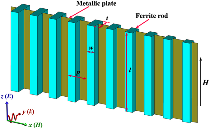
Schematic diagram of the magnetically tunable metasurface.
In order to reveal the magnetically tunable mechanism, firstly the transmission intensity and phase difference of the metasurface with the same ferrite rod thicknesses have been investigated. Figure 2a shows the simulated transmission intensity spectra of the magnetically tunable metasurfaces with a series of ferrite rod thicknesses t. The inset shows the schematic diagram of the proposed metasurface. The applied magnetic field was set as 3400 Oe. It is obvious that for all cases, there exists a broadband transparent window when the metasurface has a uniform t value. As t increases, this transparent window turns to low frequency direction. Figure 2b shows the simulated transmission intensity spectra of the magnetically tunable metasurface under a series of applied magnetic fields H. The ferrite rod thickness is set as 3.0 mm. As H increases from 3300 Oe to 3600 Oe, the center frequency of the transparent window increases from 10.6 GHz to 11.4 GHz, which shows a magnetically tunable behavior.
Figure 2.
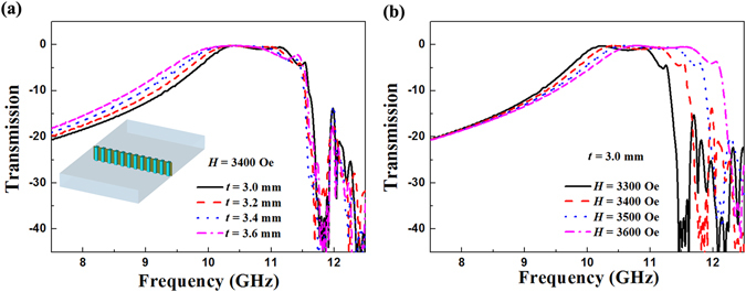
Simulated transmission intensity spectra of the magnetically tunable metasurface. (a) The ferrite rods with a series of thicknesses t. The inset shows the schematic diagram of the proposed metasurface. (b) The ferrite rods under a series of applied magnetic fields H.
To confirm the above simulated results, transmission intensity spectra of the fabricated magnetically tunable metasurfaces were measured. Figure 3a shows the schematic experimental setup of the metasurfaces placed in the planar waveguide. The bias magnetic field applied in the z direction is provided by the electromagnets. Figure 3b shows the measured transmission intensity spectra of the magnetically tunable metasurfaces with a series of ferrite rod thicknesses t. The transparent window turns to low frequency direction as t increases from 3.0 mm to 3.6 mm. The bandwidth of the transparent window is 1.1 GHz when t = 3.6 mm and H = 3400 Oe. The measured transmission intensity spectra of the magnetically tunable metasurfaces under a series of applied magnetic fields H are shown in Fig. 3c. Due to the material defects and experimental errors, the measured insertion losses are lower than the simulated ones. It can be seen that the center frequency of the transparent window increases from 10.4 GHz to 11.1 GHz with the increasing of the applied magnetic field from 3300 Oe to 3600 Oe, which demonstrates a magnetically tunable property. Obviously, the measured results are in good agreement with the simulated ones.
Figure 3.
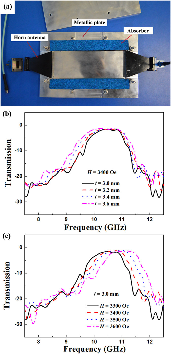
Expeiment demonstrating the magnetically tunable metasurface. (a) Photograph of the parallel plate waveguide composed of two horn antennas, two metal plates and absorbers. Measured transmission intensity spectra of the magnetically tunable metasurface. (b) The ferrite rods with a series of thicknesses t. (c) The ferrite rods under a series of applied magnetic fields H.
By interacting with the magnetic field of an electromagnetic wave, ferromagnetic resonance (FMR) can take place in a ferrite under a certain applied magnetic field. The FMR frequency of the ferrite can be expressed by20
| 1 |
where γ is the gyromagnetic ratio, H is the applied magnetic field, M s is the saturation magnetization, N x, N y, and N z are the demagnetization factor at x, y, and z directions, respectively. Based on the above FMR theory, extraordinary transmission can be realized by combining the ferrite rods with the metallic foils21. When the FMR takes place at the resonance frequencies, the ferrite rods act as waveguides which can efficiently transmit the electromagnetic wave through the metasurface. According to Eq. (1), the frequency of the passband decreases as the ferrite rod thickness (along y direction) increases, and it increases as the applied magnetic field increases. Thus the theoretical prediction is in good agreement with our simulated and experimental results.
For efficient wave-front manipulation, the capability to create a desired discrete phase gradient at a given operation frequency is of paramount importance22. Hence, phase of the proposed metasurfaces are also simulated and measured. All the ferrite rods in one metasurface still have the same thickness value. Before putting the metasurface into the parallel plate waveguide to measure the phase shift, the phase of the incoming wave is normalized to 0° by de-embedding. Figure 4a shows the dependence of phase difference at 11.0 GHz on the ferrite rod thickness t. The applied magnetic field is fixed at 3400 Oe. The lines and dots represent the simulated and measured results, respectively. Both the simulated and measured results show that the phase difference varies smoothly. The phase decreases from 161° to 15° as t increases from 2.6 mm to 4.0 mm. Figure 3b shows the dependence of phase difference at 11.0 GHz on the applied magnetic field H. The ferrite rod thickness is 3.0 mm. It can be seen that the phase increases from 31° to 170° as H increases from 3300 Oe to 3600 Oe. Thus Fig. 4 successfully proves that our proposed metasurface can function as an efficient resonant structure, and provides full controlment on the phase of the transmission waves.
Figure 4.
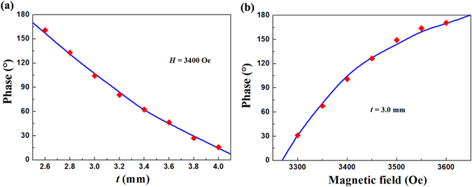
The dependence of phase difference at 11.0 GHz. (a) The dependence of phase difference on the ferrite rod thickness t and (b) the applied magnetic field H. The lines and dots represent the simulated and measured results, respectively.
Electric field distributions for magnetically tunable metasurface
The spectra of transmission intensity and phase difference show that wave-front manipulation can be achieved by selecting appropriate values of the ferrite rod thickness. By tuning the thickness of the ferrite rods, phase gradient is assigned along x axis on the metasurface, so that the transmission wave can be refracted to a prescribed direction. Three samples with linear phase gradients are used to illustrate this concept. Table 1 presents the ferrite rod thicknesses t n of the proposed metasurfaces. The ferrite rod thicknesses for sample 1 have the same value. The thickness gradient ∆t between two adjacent ferrite rods for samples 2 and 3 are 0.2 mm and 0.4 mm, respectively. To demonstrate the wave manipulation behavior of this design, we simulated the electric field distributions in the xy-plane for a plane wave propagated through the metasurfaces by using CST Microwave Studio TM. Figure 5a shows the simulated electric field distribution for sample 1 with H = 3400 Oe. Due to ∆t = 0, the electromagnetic wave propagates through the metasurface without deflection. Figure 5b shows the simulated electric field distribution for sample 2 with H = 3400 Oe. The plane wave propagates through the metasurface with a certain deflection angle. Figure 4c shows the simulated electric field distribution for sample 3 with H = 3400 Oe. It is obvious that the deflection angle for sample 3 is bigger than that for sample 2. The deflection angle can be expressed by23
| 2 |
where λ is wavelength, Φ is the phase difference at a local point brought by the metasurface, dΦ/dx is the gradient of phase difference along x axis. From Eq. (2), the deflection angle θ t is influenced by dΦ/dx. Based on the data shown in Fig. 3a, as ∆t of sample 3 is bigger than that of sample 2, dΦ/dx for sample 3 is therefore bigger than that for sample 2, which leads to a larger deflection angle for sample 3. Figure 4d shows the simulated electric field distribution for sample 2 with H = 3600 Oe. Based on the data shown in Fig. 3b, the sign of dΦ/dx for metasurfaces with different t is opposite to that for metasurfaces under different H. Hence, as H increases, the deflection angle decreases, which exhibits a magnetically tunable behavior.
Table 1.
Ferrite rod thicknesses t n of the proposed metasurfaces.
| Sample | t 1 | t 2 | t 3 | t 4 | t 5 | t 6 | t 7 | t 8 | t 9 | t 10 | t 11 | t 12 | ∆t |
|---|---|---|---|---|---|---|---|---|---|---|---|---|---|
| 1 | 3.0 | 3.0 | 3.0 | 3.0 | 3.0 | 3.0 | 3.0 | 3.0 | 3.0 | 3.0 | 3.0 | 3.0 | 0 |
| 2 | 3.0 | 3.2 | 3.4 | 3.6 | 3.8 | 4.0 | 4.2 | 4.4 | 4.6 | 4.8 | 5.0 | 5.2 | 0.2 |
| 3 | 3.0 | 3.4 | 3.8 | 4.2 | 4.6 | 5.0 | 5.4 | 5.8 | 6.2 | 6.6 | 7.0 | 7.4 | 0.4 |
Figure 5.
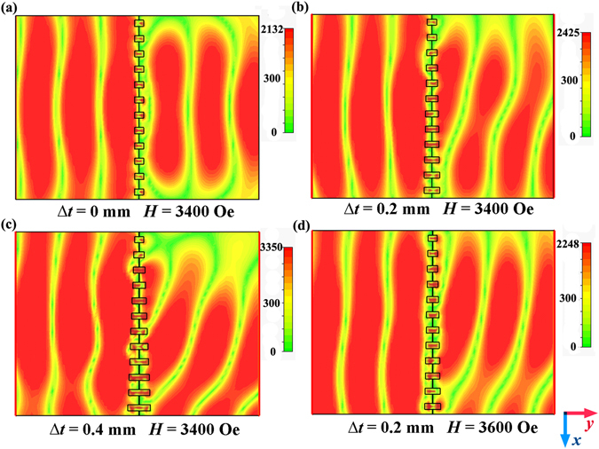
Simulated electric field distributions in the xy-plane for a plane wave propagated through the metasurfaces. (a) Sample 1 with H = 3400 Oe. (b) Sample 2 with H = 3400 Oe. (c) Sample 3 with H = 3400 Oe. (d) Sample 2 with H = 3600 Oe.
Discussion
In conclusion, a magnetically tunable metasurface composed of ferrite rods and metallic foils has been prepared. Owing to the extraordinary transmission, the metasurface provide a broadband transparent window. The amplitude and phase of the transmission wave decrease as the ferrite rod thickness increases, and increase as the applied magnetic field increases. By tuning the thickness of the ferrite rods, phase gradient is obtained. The deflection angle for the metasurfaces increases as the rod thickness gradient increases. In addition, the deflection angle decreases as the applied magnetic field increases, which exhibits a magnetically tunable behavior. This work provides a way for wave manipulation with a magnetically tunable metasurface.
Methods
Sample fabrication
The metallic structure was fabricated by circuit board plotter (LPKF Laser & Electronics Company). The thickness of the PCB substrate and copper layer are 1 mm and 0.035 mm, respectively. The ferrite material used here is commercially available yttrium iron garnet (YIG) ferrite with relative permittivity ε r = 14.5, saturation magnetization 4πM s = 1950 Oe and linewidth ΔH = 10 Oe. The width w (along x direction) of the ferrite rods is 2 mm. The length l of the ferrite rods is 10 mm, which is the same as that of the metallic slits. The lattice period p is 5 mm. The thickness t (along y direction) of the ferrite rods varies gradiently along the x direction, which are listed in Table 1. The ferrite rods were bonded with PCB plates by epoxy to form the ferrite-based metasurfaces.
Microwave measurements
The transmission properties were measured by a microwave measurement system composed of a vector network analyzer, a parallel plate waveguide (shown in Fig. 2a) and an electromagnet, which is the same as that in ref. 24. The upper and lower metal plates form the planar waveguide. The two horns antennas are used to transmit and receive the electromagnetic wave. The size of the final section for the horns is 70 × 10 mm2. The width (along x direction) and length (along z direction) of the proposed metasurfaces is 60 mm and 10 mm, respectively. The thickness (along y direction) of the proposed metasurfaces depends on the thickness of the ferrite rods. The incident wave propagates along the y axis, and the electric field and magnetic field are along the z and x axes, respectively. The samples were placed in the parallel plate waveguide and the waveguides were put in the middle of two magnets. The bias magnetic field applied in the z direction is provided by the electromagnets. The diameter of the two magnets is 100 mm, which can provide a uniform external magnetic field.
Simulations
Commercial time-domain package CST Microwave Studio TM was used to carry out the numerical predictions of the transmission intensity, phase difference and electric field distributions. All the simulated parameters of the ferrite rods and metallic foils were the same as those in the experiments. The relative permittivity, saturation magnetization and linewidth of the ferrite rods are set as 14.5, 1950 Oe and 10 Oe. The models in the simulations were set up according to the actual measurement environment. The microwave propagated along y direction with the electric field along the z direction and the magnetic field along the x direction. The boundaries in the x and z directions are set as perfect magnetic and perfect electric, respectively.
Acknowledgements
This work was supported by the National Natural Science Foundation of China under Grant Nos. 61674019 and 61574020; the Fundamental Research Funds for the Central Universities under Grant No. 2015RC18; the Fund of State Key Laboratory of Information Photonics and Optical Communications (Beijing University of Posts and Telecommunications), China.
Author Contributions
H.Y. conceived the idea and designed experiments. H.Y., T.Y., Q.W., performed the experiments. H.Y. and M.L. developed the post-processing treatments of the experimental data. H.Y. wrote the paper. All authors contributed to scientific discussion and critical revision of the article.
Competing Interests
The authors declare that they have no competing interests.
Footnotes
Publisher's note: Springer Nature remains neutral with regard to jurisdictional claims in published maps and institutional affiliations.
References
- 1.Veselago VG. The Electrodynamics of Substances with Simultaneously Negative Values of ɛ and μ. Sov. Phys. Usp. 1968;10:509. doi: 10.1070/PU1968v010n04ABEH003699. [DOI] [Google Scholar]
- 2.Smith DR, Pendry JB, Wiltshire MCK. Metamaterials and Negative Refractive Index. Science. 2004;305:788. doi: 10.1126/science.1096796. [DOI] [PubMed] [Google Scholar]
- 3.Kang L, Zhao Q, Zhao H, Zhou J. Magnetically tunable negative permeability metamaterial composed by split ring resonators and ferrite rods. Opt. Express. 2008;16:8825. doi: 10.1364/OE.16.008825. [DOI] [PubMed] [Google Scholar]
- 4.Burokur SN, Ourir A, Daniel J, Ratajczak PP, Lustrac AD. Highly directive ISM band cavity antenna using a bi-layered metasurface reflector. Microwave Opt. Technol. Lett. 2009;51:1393. doi: 10.1002/mop.24391. [DOI] [Google Scholar]
- 5.Yu N, Capasso F. Flat optics with designer metasurfaces. Nat. Mater. 2014;13:139. doi: 10.1038/nmat3839. [DOI] [PubMed] [Google Scholar]
- 6.Zhu W, Xiao F, Kang M, Premaratne M. Coherent perfect absorption in an all-dielectric metasurface. Appl. Phys. Lett. 2016;108:121901. doi: 10.1063/1.4944635. [DOI] [Google Scholar]
- 7.Cheng J, Ansari-Oghol-Bei Dg, Mosallaei H. Wave manipulation with designer dielectric metasurfaces. Opt. Lett. 2014;39:6285. doi: 10.1364/OL.39.006285. [DOI] [PubMed] [Google Scholar]
- 8.Wan X, Xiang Jiang W, Feng Ma H, Jun Cui T. A broadband transformation-optics metasurface lens. Appl. Phys. Lett. 2014;104:151601. doi: 10.1063/1.4870809. [DOI] [Google Scholar]
- 9.Azad AK, et al. Metasurface Broadband Solar Absorber. Sci. Rep. 2016;6:20347. doi: 10.1038/srep20347. [DOI] [PMC free article] [PubMed] [Google Scholar]
- 10.Wu C, Cheng Y, Wang W, He B, Gong R. A polarization independent phase gradient metasurface for spoof plasmon polaritons coupling. J. Opt. 2016;18:025101. doi: 10.1088/2040-8978/18/2/025101. [DOI] [Google Scholar]
- 11.Chen X, Zhou H, Liu M, Dong J. Measurement of Orbital Angular Momentum by Self-Interference Using a Plasmonic Metasurface. IEEE Photonics J. 2016;8:4800308. [Google Scholar]
- 12.Yang Y, Wang H, Yu F, Xu Z, Chen H. Coxsackievirus A16 induced neurological disorders in young gerbils which could serve as a new animal model for vaccine evaluation. Sci. Rep. 2016;6:20219. doi: 10.1038/srep20219. [DOI] [PMC free article] [PubMed] [Google Scholar]
- 13.Zhang X, et al. Metasurface-based broadband hologram with high tolerance to fabrication errors. Sci. Rep. 2016;6:19856. doi: 10.1038/srep19856. [DOI] [PMC free article] [PubMed] [Google Scholar]
- 14.Yu S, et al. Design, fabrication, and measurement of reflective metasurface for orbital angular momentum vortex wave in radio frequency domain. Appl. Phys. Lett. 2016;108:121903. doi: 10.1063/1.4944789. [DOI] [Google Scholar]
- 15.Yu N, et al. Flat Optics: Controlling Wavefronts With Optical Antenna Metasurfaces. IEEE J. Sel. Top. Quantum Electron. 2013;19:4700423. doi: 10.1109/JSTQE.2013.2241399. [DOI] [Google Scholar]
- 16.Miao, Z. et al. Widely Tunable Terahertz Phase Modulation with Gate-Controlled Graphene Metasurfaces. Phys. Rev. X5 (2015).
- 17.Gutruf P, et al. Mechanically Tunable Dielectric Resonator Metasurfaces at Visible Frequencies. ACS Nano. 2016;10:133. doi: 10.1021/acsnano.5b05954. [DOI] [PubMed] [Google Scholar]
- 18.Yao Y, et al. Electrically tunable metasurface perfect absorbers for ultrathin mid-infrared optical modulators. Nano Lett. 2014;14:6526. doi: 10.1021/nl503104n. [DOI] [PubMed] [Google Scholar]
- 19.Ee H-S, Agarwal R. Strong Exciton-Plasmon Coupling in MoS2 Coupled with Plasmonic Lattice. Nano Lett. 2016;16:2818. doi: 10.1021/acs.nanolett.6b00618. [DOI] [PubMed] [Google Scholar]
- 20.Bi K, Zhou J, Zhao H, Liu X, Lan C. Tunable dual-band negative refractive index in ferrite-based metamaterials. Opt. Express. 2013;21:10746. doi: 10.1364/OE.21.010746. [DOI] [PubMed] [Google Scholar]
- 21.Bi K, Liu W, Guo Y, Dong G, Lei M. Magnetically tunable broadband transmission through a single small aperture. Sci. Rep. 2015;5:12489. doi: 10.1038/srep12489. [DOI] [PMC free article] [PubMed] [Google Scholar]
- 22.Chen, H. et al. Manipulating unidirectional edge states via magnetic plasmonic gradient metasurfaces. Plasmonics 1–12, (2016).
- 23.Wei Z, et al. Highly efficient beam steering with a transparent metasurface. Opt. Express. 2013;21:10739. doi: 10.1364/OE.21.010739. [DOI] [PubMed] [Google Scholar]
- 24.Bi K, et al. Magnetically tunable Mie resonance-based dielectric metamaterials. Sci. Rep. 2014;4:7001. doi: 10.1038/srep07001. [DOI] [PMC free article] [PubMed] [Google Scholar]


