Abstract
We formed a database gathering the wavefront aberrations of 50 healthy eyes measured with an original custom-built Shack-Hartmann aberrometer at a temporal frequency of 236 Hz, with 22 lenslets across a 7-mm diameter pupil, for a duration of 20 s. With this database, we draw statistics on the spatial and temporal behavior of the dynamic aberrations of the eye. Dynamic aberrations were studied on a 5-mm diameter pupil and on a 3.4 s sequence between blinks. We noted that, on average, temporal wavefront variance exhibits a n−2 power-law with radial order n and temporal spectra follow a f−1.5 power-law with temporal frequency f. From these statistics, we then extract guidelines for designing an adaptive optics system. For instance, we show the residual wavefront error evolution as a function of the number of corrected modes and of the adaptive optics loop frame rate. In particular, we infer that adaptive optics performance rapidly increases with the loop frequency up to 50 Hz, with gain being more limited at higher rates.
OCIS codes: (010.7350) Wave-front sensing; (330.7327) Visual optics, ophthalmic instrumentation; (220.1080) Active or adaptive optics
1. Introduction
Ultra-high resolution retinal imaging has proven to be a useful tool to diagnose retinal disorders at the earliest stages, to monitor the progression of retinal diseases as well as the effect of new curative drugs, and to improve our understanding of the eye [1]. Such imaging systems need adaptive optics (AO) that provide real-time correction of both low and high order ocular aberrations in order to attain diffraction-limited performance over medium to large pupils [2–4]. Current state-of-the-art AO-assisted retinal imaging research systems yield unprecedented resolution, making individual retinal cell stimulation [5] and rod photoreceptor imaging [6] possible. Nevertheless, effort still has to be made to reduce their cost and size, and to ensure that the highest performance is reached for any patient. This is all the more crucial for emerging therapeutic applications such as AO-assisted laser surgery [7], which require highly reliable systems working consistently on all patients.
In order to better understand the limitations of current AO systems, it is very informative to analyze the AO error budget, i.e., to list and quantify the various contributors to the residual wavefront variance remaining after AO correction. The main terms typically considered are: the wavefront sensing error, in particular due to the noise on the wavefront sensor camera; the fitting error, due to the fact that a deformable mirror with a finite number of actuators cannot perfectly compensate the ocular aberrations; and the temporal error due to the time lag between sensing and correction. Such an analysis was carried out on a few eyes by Evans et al., so as to identify the main sources of residual wavefront variance on their specific apparatus [8].
Apart from characterizing existing devices, the error budget can also be a powerful tool to design future systems: after expressing the various terms as a function of the AO system parameters (AO loop frequency, number of actuators in the deformable mirror, etc. . .) and specifying a target value for the total residual wavefront variance, a parametric analysis can be performed to select the AO system parameters which actually meet this target value. Of course, this parametric study must rely on a statistical model of the ocular aberrations.
For static aberration, such a statistical model does exist: two large studies have analyzed the spatial statistics of the static ocular aberrations over the population [9, 10], from which Doble et al. have derived the required specifications of the corrector depending on the targeted performance [11,12]. Unfortunately, our knowledge on the temporal statistics underlying dynamic aberrations is still incomplete. Time-varying aberrations have been the object of many studies [13–19], but only a few of them have collected high spatial resolution data, and only at a moderate temporal resolution (100 Hz) [16, 17]. Finally, up to now, not enough measurements were taken to draw a statistically relevant model of the dynamic ocular aberrations (the aberrations were characterized on 1 to 6 eyes at most). It seems all the more important to assess the temporal statistics of the dynamic aberrations, in order to show that experimental AO systems are often limited by the frame rate of the AO loop [8,14].
In this paper, we present the first characterization of ocular aberrations with both high temporal (sampling frequency at 236 Hz) and spatial (22 lenslets across a 7-mm diameter pupil) resolution, on a large population consisting of 50 healthy eyes, in order to come up with a statistical description of dynamic ocular aberrations reflecting the inter-subject variability. Then, we analyze the resulting implications on the AO error budget through the simulation of a close-loop wavefront correction. We then propose practical tools for AO system design, such as considering the evolution of the residual wavefront error when increasing the number of corrected modes, or when increasing the frame rate of the AO loop.
First, in Sect. 2, we present details on the population, on the setup and on the data processing involved in the study. Then, in Sect. 3, we report our findings on the statistics of dynamic aberrations in our population. Finally, in Sect. 4, we use the data from the aberration measurements to analyze AO error budget terms.
2. Methods
2.1. Experimental set-up
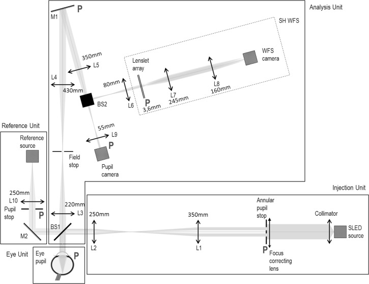
We have built a custom-designed Shack-Hartmann (SH) wavefront sensor (WFS) to characterize the dynamic aberrations of the eye. A diagram of the full system can be found in Fig. 1. It comprises four units: an injection unit delivering the near infrared WFS beacon at 833 nm; an eye unit coming down to the eye (real/artificial); an analysis unit collecting the back-scattered light from the eye on two instruments, the WFS and a pupil camera; and a reference unit composed of a reference eye used to calibrate the system (in particular, to acquire the reference SH spots).
Fig. 1.
Schematic drawing of the experimental set-up, comprising a Reference Unit (used to acquire the reference wavefront), an Injection Unit creating a point source on the retina and an Analysis Unit with a custom-made Shack-Hartmann Wavefront Sensor (SH WFS), in parallel with a pupil camera.(L: lens - associated focal lengths are reported on the schematic drawing, BS: beam splitter, M: mirror). All pupil planes (marked with P) are optically conjugated.
The injection unit, which aims to create an artificial source on the retina for wavefront sensing, uses a 833-nm SLD (Superluminescent Diode) (EXALOS) with a 50-nm spectral bandwidth. Spatial noise introduced by speckle is substantially reduced by the short coherence length of the SLD (although an even further reduction may be possible by insertion of a scanning mirror [13]). Moreover, pupil plane residual speckles, induced by scatterers having a typical lateral size of 1 μm, are larger than the subaperture diameter (see also Fig. 10 in App. A for experimental evidence). As a consequence the authors believe that speckle noise has a negligible impact on WFS data. A focus correction is provided for ametropic subjects through ophthalmic lenses which were inserted in the injection unit (and thus not seen by the WFS). The injection unit also offers filtration of specular corneal reflections through an annular pupil stop in pupil space (in the eye pupil space, the external and internal diameters are 5 mm and 2.1 mm respectively), and a fixation target, which is the WFS beacon itself at infinity (this is possible because a part of its spectrum is in the visible range). The SLD is also used as a reference source in reference unit.
Fig. 10.
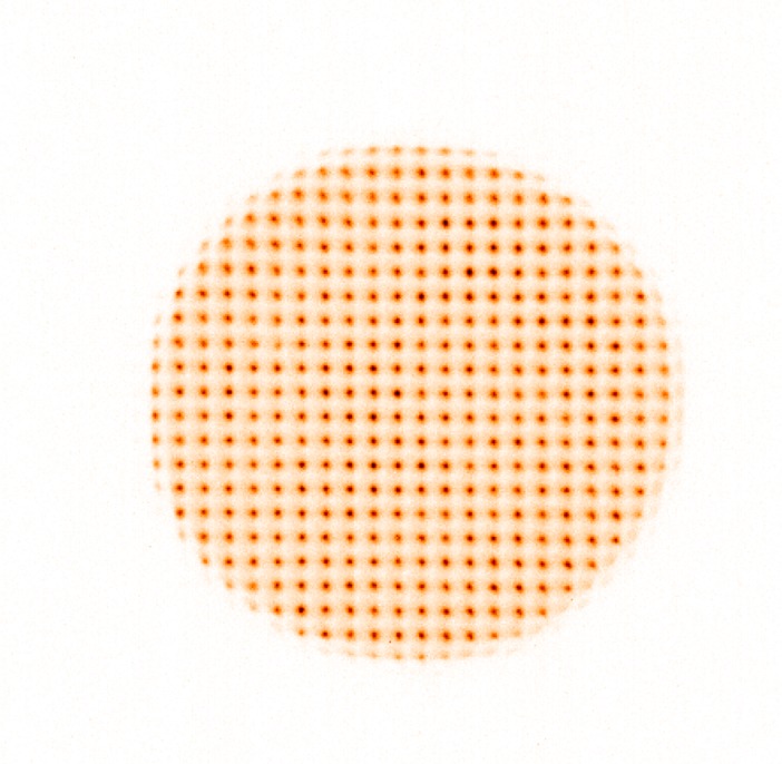
Example of Shack-Hartmann wavefront sensor image for one typical eye.
The analysis unit splits into a pupil camera (used in the scope of this paper only as a guide to position the eye pupil) and a WFS, designed to provide highly resolved measurements of the ocular wavefront. Thus, it features a 31×33 lenslet array (143 μm subaperture diameter and 3.6 mm focal length) and a sCMOS (Scientific Complementary Metal-Oxide-Semiconductor) camera (Pco.Edge) running at 236 Hz (i.e. grabbing 236 images per second) with a 450×480 pixels region of interest, leading to a 10 mm maximum pupil. An optical relay is used to image the lenslet focal plane to the detector plane. Typically for a 7-mm diameter pupil, 22 lenslets were illuminated across the diameter and the pupil field allowed displacements of the pupil of ±1.5 mm, which was high enough given the fact that the subjects were stabilized by a chin and forehead rest in order to prevent head movements. A field stop on the analysis path corresponding to approximately 1.2° on the retina is used to limit stray light and multiply-scattered background light, at the cost of a reduced range of measurable sphere, limited to ±2.3 D at 833 nm.
2.2. Population
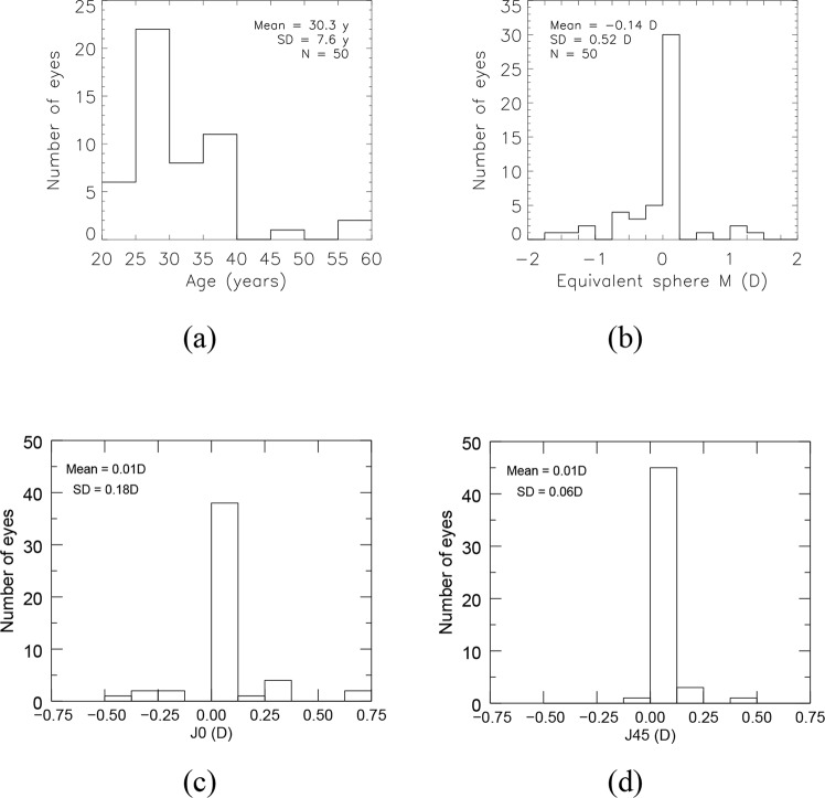
A total of 50 healthy eyes were examined with the aberrometer, 4 of which had undergone LASIK surgery. 29 people took part in the study. Most eyes were in the 23–38 years old range, as shown in Fig. 2(a). Concerning the refractive correction of our population, it was low; average spherical equivalent, M [20], of our population was −0.1 D and the associated standard deviation was 0.5 D; average cylindrical components, J0 and J45 [20], were zero (see Fig. 2(b), 2(c) and 2(d)). These values of refractive error were taken from the spectacle prescription of our population. As a consequence, they are ±0.125 D accurate at best and effective for the visible spectrum (optimal at 570 nm [21]). Given the longitudinal chromatic aberration (LCA) reported between our operating wavelength (833 nm) and 570 nm [22, 23], we expect a shift of the reported average spherical equivalent towards positive values at 833 nm.
Fig. 2.
Description of the 50-eye population regarding (a) age, (b) spherical equivalent, (c) cylindrical component J0, (d) cylindrical component J45. Spherical equivalent and cylindrical components were taken from the spectacle prescription of our population.
2.3. Data acquisition and reduction procedure
Measurements were performed in normal conditions without any pupil dilation, nor cycloplegia, in a dark room, leading to the largest accessible natural pupil dilation. Such conditions have been considered in other studies of time-varying ocular aberrations [14–16].
All patients signed an informed consent form, as defined in our institution review board procedure (CPP Ile-de-France). Prior to the subject’s arrival, background and reference images were acquired on the WFS. Then, the procedure was done as follows: focus of the WFS beacon was approximately adjusted given the spectacle prescription of the subject and taking into account the LCA between 570 nm and 833 nm; it was then fine-tuned through a subjective adjustment until the image of the WFS beacon appeared to the subject as a well-focused point source (this adjustment was done at low power); the optical power of the SLD was then set to get 29 μW on the eye unit (that is a tenth of the maximum permitted power by the ANSI Z136.1 norm for a coherent source at 833 nm and a 0.16-cm2-illuminated surface on the cornea) ; the patient was asked to blink just before the acquisition started and to stay still and stare at the fixation target (WFS beacon itself) for the duration of the video acquisition (20 seconds per eye).
The raw data consisted of 50 series of 20-second-long WFS camera sequences at 236 Hz (complemented with the 50 associated reference slopes and WFS camera background acquisitions performed right after each patient acquisition). Long-exposure background images were subtracted to get rid of spatial noise and ambient stray light. Then for all 50 eyes, we extracted a continuous 3.4 s time sequence (i.e., 808 frames) without blinks. From these 50 series of 3.4-second-long background-subtracted WFS sequences, we derived the ocular aberrations following the procedure described below.
Slope computation SH spot centroids were determined by computing an adaptive thresholded center of gravity within each subaperture image, and then subtracting the reference centroids (computed with the same method on the WFS reference measurements, acquired on the reference source right after patient acquisition).
Analysis pupil We first computed the area of the SH WFS that is illuminated during the whole 3.4 s time sequence. Since the size of the eye pupil varied over the population and the eye moved over the acquisition [24], we defined a 5 mm analysis pupil Panalysis inside the area corresponding to the intersection of all eye pupils recorded through the sequence of interest (3.4 s). Similar analysis pupil, ranging from 4 to 5.8 mm, was adopted in time-varying ocular aberrations studies [13–19]
- Wavefront reconstruction For each sequence (i.e., for each eye), we built an analytic WFS model MWFS (Panalysis) linking the Zernike coefficients to the slopes of the subapertures within Panalysis (with at least 50 % of their surface inside Panalysis). The Zernike coefficients, at time t, {ai (t, eye)} are then estimated from the measured slopes S(t, eye) with a least-square estimation through:
with † denoting the generalized inverse. Given the number of subapertures encompassed by the chosen analysis pupil (16 × 16), only the Zernike coefficients up to 45 (ie up to the 8th radial order) were considered for the 5-mm diameter analysis pupil. In the end, the time-varying wave aberration function W could fully be described on the 5-mm diameter analysis pupil for each eye as an expansion of Zernike polynomials Z4 (focus) to Z45 as:(1)
with Zernike polynomials ranked according to Noll’s convention [25] (see Sect. 2.4).(2)
2.4. Definitions and notations
Our wavefront data depends on time, space and population. Mean and variance on these data can therefore be computed over these three variables. We adopt the following notations:
mean and standard deviation over time of a quantity x will be denoted x̄ and σt (x);
the distribution of x over the population will be reported as mean ± SD, where mean indicates the mean value of x over the population and SD the standard deviation of x over the population;
- the Squared WaveFront Error (SWFE) defined as the time-averaged sum of the squared Zernike coefficients over all modes (or over modes of a specific radial order) was used to quantify the level of aberrations; it splits into a static SWFE and a dynamic SWFE, as follows:
(3)
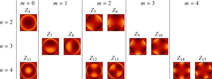
Zernike polynomials are ranked according to Noll’s convention and recalled on Fig. 3 from the 2nd to the 4th radial order. In accordance with convention, we will refer to aberration modes with a radial order greater than or equal to 3 as Higher-Order Aberrations.
Fig. 3.
Zernike polynomials Zi from the 2nd to the 4th radial order ordered according to Noll’s convention by increasing radial order n (the degree of the polynomial) and increasing azimuthal frequency m (the number of cycles of the sinusoidal function) with odd indexes i indicating the Zernike function is in sine phase and even indexes indicating the Zernike function is in cosine phase.
2.5. Accuracy of our aberrometry data
In order to assess the level of precision of our aberrometry data, we considered the following wavefront sensing error SWFEWFS budget:
| (4) |
We checked that the aliasing error SWFEaliasing, which represents the error due to the limited sampling of the WFS as compared to the spatial dynamics of the ocular aberrations, could be ignored given the high number of lenslets encompassed by the pupil (16 × 16) [11,12].
The noise error term SWFEnoise corresponds to the propagation of the WFS camera detection noise (see Sect. 4.1 for further details). It splits (as in Eq. (3)) into a dynamic part – quantified experimentally as 2.0 × 10⁻⁴ μm2±1.5 × 10⁻⁴ μm2 (mean ± SD) on a 5-mm diameter pupil – and a static part which could be neglected considering that the detection noise is centered.
The Non-Common Path Aberrations (NCPA) error term SWFENCPA is brought by the non-common path aberrations between the reference eye and the artificial eye (refer to the set-up description in Sect. 2.1). Its static part amounted to 1.5 × 10⁻³ μm2 on a 5-mm diameter pupil; its dynamic part, linked to the local turbulence on the optical bench, was shown to be negligible compared to the noise error.
To conclude, the wavefront sensing error was:
| (5) |
Note that measurements were performed without cycloplegia, which may slightly change 2nd order statistics.
3. Experimental characterization of ocular aberrations
We analyzed the spatio-temporal statistics of the aberration distribution over our population, first on static aberrations, then on dynamic aberrations.
3.1. Static aberrations of our population
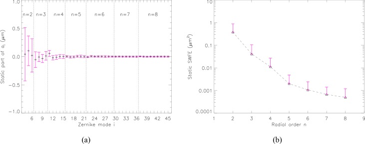
We analyzed the static aberrations of our 3.4-second-long sequences ( being the time average of ai (t, eye), see Sect. 2.4). For each mode, Fig. 4(a) shows the mean level and standard deviation of static aberrations over the population. We observe declining mean values (Fig. 4(b) - further detail below) and standard deviations (Fig. 4(a)) with radial order.
Fig. 4.
Distribution of the static part of the aberrations over the population for a 5-mm diameter pupil. (a) Zernike coefficients from the 2nd to the 8th radial order over the 50-eye subpopulation. Symbols indicate mean values of and error bars plus and minus one standard deviation from the mean values. (b) Contribution of each radial order to the total static SWFE. Symbols indicate mean values of and error bars plus one standard deviation from the mean values.
Average static defocus measured on a 5-mm diameter pupil is over the population, which corresponds to a spherical equivalent M̄ = −0.05 D±0.52 D. This is in agreement with the average spherical equivalent given by the spectacle prescription of the 50-eye subpopulation, which was −0.1 D±0.5 D. Concerning Higher-Order modes, the distribution of each mode in our population, except spherical aberration (Z11), is roughly centered around zero. Average static spherical aberration measured on a 5-mm diameter pupil is slightly positive ( ).
Mean static SWFE, which correspond to the mean over the population of the static SWFE (equal to , see Eq. (3)), is a good indicator of the level of static aberration of a typical eye. Figure 4(b) reports the contribution of each radial order to the total static SWFE, showing decreasing SWFE with radial order (showing that mean values decrease with radial order). Second-order aberrations represent 87 % of the total static aberrations; this depends highly on the population, we remind the reader that ours presents reduced static aberrations (with M̄, J̄0 and closed to zero, see Sect. 2.2). For the remaining orders, we note that 73 % of the energy of Higher-Order Aberrations (3rd order and above) are concentrated in the 3rd order, 20 % in the 4th, 4 % in the 5th, 2 % in the 6th and 1 % in the 7th. This is consistent with the distribution of static aberrations and the description of the mean eye in previous studies [9,10,26].
3.2. Description of the dynamic aberrations of our population
3.2.1. Time series and dynamic SWFE
Figure 5 shows the time series of the first Zernike coefficients for a typical eye, grouped by radial order. Strong low frequency variations can be seen for low orders, with spikes or steps roughly every 0.5 s. The traces show smaller temporal variance for higher radial orders.
Fig. 5.
Experimental example of temporal series of Zernike coefficients from the 2nd to the 4th radial order on one eye across a 5-mm diameter pupil during a 3.4-second-long sequence. Modes are attributed different colors and are specified beside the traces. The traces have been vertically shifted for clarity. As a consequence, mean values do not represent static aberrations. (a) Second-order dynamic aberrations (a4, a5, a6). (b) Third-order dynamic aberrations (a7, a8, a9, a10). (c) Fourth-order dynamic aberrations (a11, a12, a13, a14, a15).
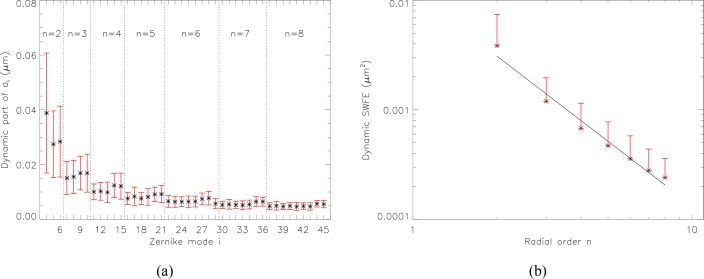
This smaller temporal variance for high order modes is confirmed statistically in our population in Fig. 6(a), where the distribution of the dynamic part of the aberrations (i.e., the standard deviation over time of the aberrations) for a 5-mm diameter pupil is presented.
Fig. 6.
Distribution of the dynamic part of the aberrations over the population. (a) Zernike coefficients from the 2nd to the 8th radial order over the population across a 5-mm diameter pupil. Symbols indicate mean values of σt (ai (eye)) and error bars indicate plus and minus one standard deviation (over the population) from the mean values. (b) Contribution of each radial order to the total dynamic SWFE for a 5-mm diameter pupil. Symbols indicate mean values of and error bars indicate plus one standard deviation from the mean values. A linear fit, represented by the solid line, models the dynamic SWFE by a n−2 power-law.
Temporal variations of defocus are somewhat specific. They are quite high compared to the temporal variations of astigmatism and vary a lot over the population. Peak-to-valley variations of defocus amount to 0.21 D±0.09 D over our population. The standard deviation over time of defocus, describing the RMS fluctuations of defocus, is 0.04 D±0.02 D (which is in agreement with data reported by Charman et al. for low target vergence [27]). The figure also points out that, apart from defocus, all modes within a given radial order show similar mean value or standard deviation over the population.
Figure 6(b) shows the dynamic SWFE summed over each radial order n for a 5-mm diameter pupil. The values follow approximately an n−2 power-law with radial order n, shown as a straight line on Fig. 6(b).
3.2.2. Relative importance of static and dynamic SWFE
From the comparison of the dynamic SWFE (given in Fig. 6(b)) and the static SWFE (given in Fig. 4(b)), we infer that the dynamic part of the aberrations represent 2% and the static part 98% of the total SWFE, considering radial orders from the 2nd to the 8th. In fact, dynamic SWFE is below 2.0 × 10⁻² μm2 for all eyes of our population, in other words, the corresponding Strehl ratio (SR) (considering only this error) is 33 % at worst (see Table 1). If considering the best quintile (i.e. the best 20 % eyes), the error is below 3.4 × 10⁻³ μm2, corresponding to a SR of 82 %.
Table 1.
Repartition over the population of the dynamic SWFE and associated Strehl ratio (SR). Strehl ratios are computed at 833 nm as : .
| Quintile | 1-st (20 %) | 2nd(40 %) | 3rd(60 %) | 4th(80 %) | 5th(100 %) |
|---|---|---|---|---|---|
| SWFEdyn(μm2) | 3.4 × 10⁻³ | 4.6 × 10⁻³ | 6.6 × 10⁻³ | 8.3 × 10⁻³ | 2.0 × 10⁻² |
| SR (%) | 82 | 77 | 69 | 62 | 33 |
These statistics indicate that the dynamic part of the aberrations is very small on a time scale of a few seconds (considering that our analysis sequence is 3.4 s long, so that all the evolutions at frequencies below 0.3 Hz are seen as static). In terms of correction, it means that an acceptable quality could be reached by compensating only for the quasi-static aberrations (i.e., with a 0.3 Hz bandwidth).
Yet, for some applications, such as AO-assisted laser surgery [28], a 2 × 10⁻²μm2 residual SWFE may still be too high, calling for a correction not only of the (quasi-)static aberrations, but also of the dynamic aberrations. To determine the specification for the AO sampling frequency, we analyzed the frequency content of dynamic aberrations.
3.2.3. Temporal spectra
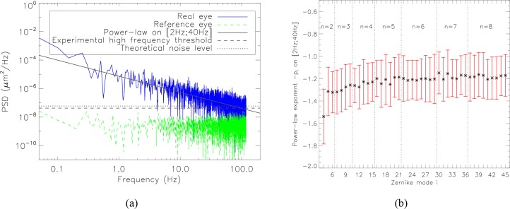
In order to study the frequency content of dynamic aberrations, we computed the power spectral densities (PSD) of each time series of Zernike coefficients. As in [17], for all measurements, we systematically removed any part of the signal that was related to the blink interval (e. g. tear film break-up and build-up, eye movement). We observed linearly decreasing PSD with frequency f on a loglog scale, which confirms the f−pi power-law previously proposed to model the temporal spectra of aberrations [13–18]. A typical example of temporal spectra of Zernike coefficients is given in Fig. 7(a). The photon noise level is reached at around 60 Hz, where a high frequency plateau appears. The level of this experimental noise plateau is in line with the expected value computed analytically from the flux within the SH spot and SH spot size (see Sect. 4.1 for details). Figure 7(a) also displays the local turbulence level on the optical bench, calibrated on the reference source. This contributor is clearly negligible in the ocular aberration measurements, which was checked for every eye and for every mode.
Fig. 7.
Power-law model of the temporal PSD of the aberration time series. (a) PSD of vertical coma (a7) measured on a real eye, in blue. The solid line indicates the power-law regression f−pi. The dotted straight line indicates the theoretical noise level (see Sect. 4.1 for details). The dashed straight line indicates the experimental high-frequency plateau of the temporal spectrum. For information, the level of local turbulence in the optical bench is given in green (corresponding to an acquisition at high flux on an artificial eye).(b) Distribution of the power-law exponent for each Zernike mode i up to the 8th order over the population for a 5-mm diameter pupil. Symbols indicate mean values of −pi and error bars plus and minus one standard deviation from the mean values.
Figure 7(b) gives the distribution of the power-law exponent −pi for each Zernike mode i over the population. We based our estimation of the power-law exponent on the frequency content between 2 and 40 Hz, in order to avoid the noise plateau at high frequency, and the noise on spectrum estimation at low frequency (the analyzed 3.4-second-long sequence contains only a few periods for frequencies below 2 Hz). This fit may therefore not accurately convey low frequency features (such as defocus energetic peaks below a few Hertz previously reported by Charman et al. [27]). However, these features are well corrected by AO loops running at a few Hertz, and our main interest in the present paper is high frequency adaptive optics loop performance assessment, for which the power-law model proposed is well adapted. We obtained the following power-law exponents:
pi = 1.5 ± 0.2 for i = 4 (defocus), that is, a drop of −4.5 dB per octave,
pi ≃ 1.3 ± 0.2 for 5 ≤ i ≤ 45, that is, a drop around −3.9 dB per octave.
Previous studies, although conducted on a more reduced population, reported temporal behavior [13–16, 29] within the error bars we obtained. With this study, we contribute additional statistics on the distribution of the power-law exponent over the population and highlighted that the power-law associated with defocus stands out from those of other modes. This power law exponent typically ranges from −1.3 to −1.2, which is much lower than the −11/3 power law exponent witnessed in atmospheric turbulence models [30]. While most Adaptive Optics control laws used in ophthalmology directly stem from astronomy, the data we present here may help when revisiting AO system design in the context of ophthalmology.
All the statistics we derived from the data, as well as information on age, gender, Lasik case, right-left eye of each subject, can be found in Data File 1 (204.7KB, CSV) (supplementary data available for the reader). Using these statistical data, it is possible to generate Zernike coefficient time series that are typical of our population. A MATLAB code generating such series can be delivered upon request from the corresponding author.
4. Implications for AO system performance
With this knowledge of the eye’s typical spatial and temporal aberration statistics, it is possible to simulate the performance of any AO loop, and use this database as a tool for designing future systems. We implemented a temporal simulation evaluating the residual aberrations aires from a closed-loop AO system based on an integrator control from the experimental time series ai of our aberrometry campaign (we call this the replay mode).
Although some teams have tried to analyze the performance of their own apparatus, quantifying the various contributors to the residual wavefront error in an error budget [8], the analysis presented hereafter is to our knowledge the first attempt to provide general guidelines for designing an AO system, via the quantification of the error budget terms as a function of its key design parameters (i.e. number of corrected modes, adaptive optics loop frame rate, wavefront sensing source power).
Adaptive optics performance specification is usually expressed in terms of Strehl Ratio, which can be approximated as . It is then logical to analyze residual aberrations through an SWFE budget. Such a simplified error budget can be expressed as:
| (6) |
where SWFEWFS represents the wavefront sensing error (see Sect.2.5 and Eq. (4)), which we consider limited to SWFEnoise in what follows, SWFEfitting the error due to the limited number of actuators of the deformable mirror, and SWFEtemporal the error due to the time lag between sensing and correction.
4.1. Noise error
The measurement noise error of the WFS, referred to as SWFEnoise, corresponds to the propagation of the WFS camera detection noise onto the WFS measurements. Knowing the WFS beacon source power and the typical reflectance of the retina (see App. A), the noise error made on each Zernike coefficient can be computed as follows:
the variance of the error on spot center of gravity estimation due to the detection noise is estimated using prior knowledge of the image distribution and the detector parameters (i.e. spatial sampling, read-out-noise), as proposed by Rousset et al. in the case of a Gaussian-shaped spot [31];
SWFE on each mode coefficient is then obtained by multiplying this centroid error variance by a modal coefficient αi (given by Rigaut et al. [32]).
Next, we can provide guidelines to compute centroid error variance in the specific case of adaptive optics in the eye.
Centroid error variance divides into a read-out noise contributor and a photon noise contributor . The latter can be further divided into a term originating from the photons in the SH spot corresponding to the flux of interest for centroid computation, and a term originating from the multiply-back-scattered photons forming the background flux of the SH images. Assuming a uniform background, this background photon noise behaves as an additional read-out noise, and is often greater than the actual camera read-out noise, which we will hence ignore in what follows.
We reformulated Rousset et al.’s expressions [31] to derive the following expressions of and (expressed in phase difference at subaperture edges in rad2):
| (7) |
with Sspot the area of the SH spot at half maximum (expressed in the retinal plane in μm2), Rdir the directional reflectance, ρbg the reflectance accounting for the background flux per unit area (see App. A for details of Rdir and ρbg), λ the WFS wavelength, Nphinc the number of photons entering the eye through the pupil and τ a factor comprising the double pass transmission of the ocular media, the quantum efficiency of the WFS camera as well as the transmission of the system from the eye to the WFS camera. This indicates that background photon noise is all the more important when the background reflectance is high, compared with the directional reflectance.
These two formulas show that photon noise is higher when the SH spots are large, which stresses the importance of emmetropic correction on the way into the eye.
4.2. Fitting error
The fitting error, referred to as SWFEfitting, is due to the limited number of actuators of the deformable mirror, leading to an imperfect correction of both static and dynamic aberrations. It can thus be split into a static and a dynamic part.
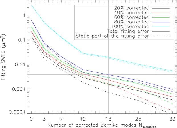
Figure 8 shows the evolution of the total fitting error that encompasses 20 %, 40 %, 60 %, 80 % and 100 % of our population as a function of the number of corrected Zernike modes. The fitting error drops rapidly until the first 12 Zernike modes are corrected (i.e., radial orders up to the 4th). This is in agreement with what we stated earlier (see Sect. 3.1), that 93% of the Higher-Order Aberrations of our population are concentrated in the 3rd and 4th orders. Figure 8 also presents the static part of the fitting error and highlights the fact that the static part of the fitting error prevails over the dynamic part, especially for low radial orders.
Fig. 8.
Fitting error in terms of SWFE as a function of the number of corrected Zernike modes Ncorrected (e.g., Ncorrected = 3 corresponds to the case where defocus, vertical and oblique astigmatisms are corrected) for various portions of the population corrected. For one eye, the total fitting error is calculated as: , with the first term corresponding to the static part of the fitting error, represented by solid lines on the graph, and the second term corresponding to the dynamic part, represented by dashed lines on the graph.
These results provide a tool for selecting the number of actuators of the deformable mirror. For instance, it indicates that when the deformable mirror compensates for the first 18 Zernike modes (i.e., radial orders up to the 5th), 80 % of the population should have a total fitting error under 0.004 μm2 which corresponds to a Strehl ratio loss of 20 % at 833 nm; for the first 36 Zernike modes, 80 % of the population should have a total fitting error under 0.001 μm2, which corresponds to a Strehl ratio loss of 6 % at 833 nm.
4.3. Temporal error
The temporal error, referred to as SWFEtemporal, is due to the finite AO loop frequency leading to a delay between an evolution of the aberrations and its correction. The slower the loop frequency, the longer the delay, hence the greater the temporal error. This error is logically computed on the modes corrected by the loop (the contribution of the uncorrected modes to the error budget does not depend on the loop frequency, and falls into the fitting error term defined in Sect. 4.2). We considered an AO system running at a sampling frequency fs, and correcting the first Ncorrected Zernike modes (piston, tip and tilt excluded) through an integral control featuring a 2-frame delay and a loop gain G fixed to 0.5 (ensuring the usual stability margins [33]).
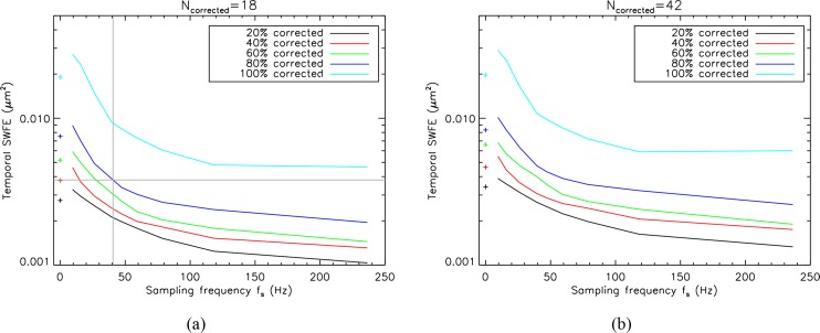
Figure 9 shows the evolution of the temporal error that encompasses 20 %, 40 %, 60 %, 80 % and 100 % of our population as a function of the sampling frequency. In Fig. 9(a), the case where the first 18 Zernike modes (i.e., up to the 5th radial order) are corrected is presented, and in Fig. 9(b), the case where the first 42 Zernike modes (i.e., up to the 8th radial order) are corrected (that is, here, the best possible spatial correction). We remind that this error is by definition the sum of the individual temporal errors over all corrected modes. By construction the temporal error is therefore higher with larger number of modes.
Fig. 9.
Temporal error SWFEtemporal as a function of the sampling frequency fs for various portions of the population corrected. For each eye, the temporal error is calculated as . The temporal fitting error is shown in solid lines for a 0.5 loop gain and in dashed lines for a 0.1 loop gain. Symbols at 0 Hz indicate the dynamic SWFE obtained without any correction. (a) For a number of corrected Zernike modes Ncorrected of 18 (i.e., up to the 5th radial order). (b) For a number of corrected Zernike modes Ncorrected of 42 (i.e., up to the 8th radial order). Zernike modes piston, tip and tilt were excluded.
These results provide a tool for selecting the sampling frequency. For instance, it indicates that at 50 Hz, the temporal error should be under approximately 0.004 μm2 for 80 % of the population when the first 42 Zernike modes are corrected, which corresponds to a Strehl ratio loss of 20 % at 833 nm. We can see that the temporal error drops rapidly until the sampling frequency reaches approximately 50 Hz to 70 Hz. A factor 2 to 3 in performance is gained when increasing the sampling frequency from 20 Hz to 50 Hz, while to gain another factor 2 in performance, the sampling frequency would have to be higher than 200 Hz.
At fs = 0 Hz, the dynamic SWFE of Table 1 (corresponding to the temporal fluctuations of the aberrations without any correction) were reported (cross symbols). We observe that below 20 Hz, the residual error is higher than these cross symbols corresponding to the level of dynamic aberrations without any correction. In other words, the loop tends to amplify the dynamic aberrations. This behavior is not surprising as frequencies at around fs/8 are slightly amplified with an integrator control for a 0.5 loop gain, and as we previously mentioned that for some modes (especially the most energetic ones, e.g., defocus), low frequency components sometimes stand out. One should probably consider using an LQG control law to reject these high-energy low-frequency components, which has been very successfully applied for high resolution imaging in astronomy [34,35]. More generally, such an LQG approach could incorporate in the control strategy the specific spatio-temporal statistical structure of the eye aberrations.
4.4. Numerical application
Let us now illustrate how theses graphs may be used to select the parameters of an adaptive optics loop for ophthalmology. Usually, the specification is expressed in terms of Strehl Ratio. This translates into a residual SWFE that can be further divided between the different error contributors. Let us consider a target Strehl ratio of 65 % at 833 nm over 80 % of the population. This yields a residual SWFE of 7.6 × 10⁻³ μm2.
We choose to split this residual SWFE equally between the temporal and fitting errors (we here neglect the other error terms of the AO error budget). Starting with the fitting error, Fig. 8 shows that in order to limit the fitting error to 3.8 × 10⁻³ μm2 over 80 % of the population, at least 18 Zernike modes are to be corrected (see indications given by grey straight lines). Then, considering 18 Zernike modes are corrected, Fig. 9(a) indicates the minimum sampling frequency that is to be chosen so as to limit the temporal error to 3.8 × 10⁻³ μm2 over 80 % of the population (see indications given by grey straight lines). It appears that to achieve the desired performance with an integrator control featuring a 2-frame delay and a loop gain of 0.5, the AO system has to run at 40 Hz at least. Recent publications indeed present AO systems with a rather high sampling frequency and also discuss its advantages, such as the AO flood-illumination camera of Rha et al. [36] and Meimon et al. [37] at 60 Hz and the AO scanning laser ophthalmoscopy of Yu et al. at 110 Hz [38].
5. Conclusion
Whereas static aberrations are well documented [9], our knowledge on the dynamic aberrations spatial and temporal statistics is still incomplete. In this paper, we have presented the first large aberrometry campaign on dynamic ocular aberrations with both high temporal (custom-built Shack-Hartmann aberrometer running at 236 Hz) and spatial (22 lenslets across a 7 mm diameter pupil) resolution, conducted on a 50 healthy eye population. The statistical analyses were performed on 3.4 s sequences without blinks on a subgroup of 50 eyes.
After comparing the static aberrations of our population to the bibliography, we could accurately describe the spatial behavior of ocular aberrations up to the 8th radial order. In particular, we confirmed the previously reported f−p power-law model for the temporal spectrum of ocular aberrations on a wider population and provided statistics of the p exponent for each mode : it amounts to 1.5 for defocus and ranges from 1.2 and 1.3 for other modes ; moreover, the power-law exponents computed do not vary greatly over the population (standard deviation is about 0.2). All the statistics we derived from the data, as well as information on age, gender, Lasik case, right-left eye of each subject, can be found in Data File 1 (204.7KB, CSV) (supplementary data available for the reader). A MATLAB code generating statistically relevant Zernike coefficient time series is available upon request, and the authors are open to sharing raw data supporting this study, and support for using it.
With this knowledge of the eye’s typical spatial and temporal aberration statistics, it is possible to simulate the performance of any AO loop, and to use this database as a tool for designing future systems. The analysis presented in this paper therefore provides AO design guidelines, via the quantification of the error budget terms as a function of its key design parameters (i.e. number of corrected modes, adaptive optics loop frame rate, wavefront sensing source power). Beyond recommending using a 50 Hz AO loop rate, we quantify how much is lost by decreasing the rate by a factor 2, and how much is gained by doubling it. This statistical model of the eye’s aberrations could be incorporated in a Linear Quadratic Gaussian control scheme, implementing a predictive control specifically tailored for the eye.
Acknowledgments
This work was partially funded by Agence Nationale de la Recherche under grant CLOVIS3D (grant number ANR-14-CE17-0011).
A. Analysis of the photons emerging from the eye and collected on the WFS camera
A.1. Definitions
Let Nphinc be the number of photons entering the eye from the WFS source. If the eye were a 100 % back-scattering Lambertian surface, the number of photons emerging from the eye would then be given by:
| (8) |
with Ω the solid angle subtended by the pupil from the point source formed on the retina by the WFS beam and T the double-pass transmission of the ocular media, which is here considered equal to 90 %.
However, only a small part of this ideal amount of photons actually emerges from the eye, the main portion of the incoming photons being transmitted or absorbed by the retina [39, 40]. Among these emerging photons, a fraction Rdir (the directional reflectance) is singly-back-scattered and forms the point source on the retina used for wavefront sensing, and a fraction Rbg is multiply-back-scattered and forms a diffuse background light patch on the retina:
| (9) |
Unlike the directional photons coming from the WFS beacon, the amount of background photons coming from the diffuse light patch depends on the field of view Sfield considered for photometric assessments. Let us assume that Sfield is totally included in the diffuse light patch formed on the retina, which we consider as approximately uniform. Then, only a portion of Rbg, proportional to Sfield, actually contributes to the photons detected on the WFS:
| (10) |
where Sbg can be considered as the surface of the total diffuse light patch. The quantity ρbg denotes the background reflectance per unit of retinal field.
Therefore, the total amount of emerging photons collected by the WFS camera from a sub-aperture in a field of view Sfield is:
| (11) |
with τbench the transmission of the system from the eye to the WFS camera, ΩμL the solid angle subtended by the image of one subaperture at the pupil plane from the point source formed on the retina by the WFS beam.
A.2. Experimental assessment of retinal reflectance
Figure 10 presents a typical Shack-Hartmann wavefront sensor image. Experimentally, the total reflectance Rtot was evaluated from the whole flux collected over the retinal field (set by the field stop in our set-up), and the directional reflectance Rdir was derived from the flux within the SH spots after diffuse background subtraction (the latter was assessed on the edge of the subaperture images). This was done for each of the 50 eyes, and for each of the 808 WFS frames of the 3.4-second-long background-subtracted WFS sequences.
The average total retinal reflectance assessed on a retinal field of 1.2° (set by the field stop in our experimental set-up) is (mean ± SD) over our 69-eye population. The average directional reflectance, evaluated from the flux within the SH spots, was . These values are very stable over time, with a temporal standard deviation of both total and directional reflectance, σt (Rtot) and σt (Rdir), worth 0.1 %±0.1 %.
It appears that retinal reflectance is rather uniform over our population, and constant over time. We conclude that the background reflectance per unit of retinal field ρbg is around 1.3 × 10⁻⁷ μm−2:
| (12) |
These values would correspond to a total retinal reflectance of 5.7 % on a retinal field of 1.5° (we remind that Rtot = Rdir + Sfield · ρbg, see Eq. (11)), which is in line with the total reflectance of approximately 6 %, given by van de Kraats et al. relative to a 1.5°-field at our working wavelength [40].
References and links
- 1.Godara P., Dubis A. M., Roorda A., Duncan J. L., Carroll J., “Adaptive optics retinal imaging: emerging clinical applications,” Optom. Vis. Sci. 87(12), 930–941 (2010). 10.1097/OPX.0b013e3181ff9a8b [DOI] [PMC free article] [PubMed] [Google Scholar]
- 2.Hofer H., Chen L., Yoon G.-Y., Singer B., Yamauchi Y., Williams D. R., “Improvement in retinal image quality with dynamic correction of the eye’s aberrations,” Opt. Express 8(11), 631–643 (2001). 10.1364/OE.8.000631 [DOI] [PubMed] [Google Scholar]
- 3.Fernández E. J., Iglesias I., Artal P., “Closed-loop adaptive optics in the human eye,” Opt. Lett. 26(10), 746–748 (2001). 10.1364/OL.26.000746 [DOI] [PubMed] [Google Scholar]
- 4.Viard C., Nakashima K., Lamory B., Paques M., Levecq X., Château N., “Imaging microscopic structures in pathological retinas using a flood-illumination adaptive optics retinal camera,” Proc. SPIE 7885, 788509 (2011). 10.1117/12.874766 [DOI] [Google Scholar]
- 5.Sincich L. C., Zhang Y., Tiruveedhula P., Horton J. C., Roorda A., “Resolving Single Cone Inputs to Visual Receptive Fields,” Nat. Neurosci. 12(8), 967–969 (2009). 10.1038/nn.2352 [DOI] [PMC free article] [PubMed] [Google Scholar]
- 6.Dubra A., Sulai Y., Norris J. L., Cooper R. F., Dubis A. M., Williams D. R., Carroll J., “Noninvasive imaging of the human rod photoreceptor mosaic using a confocal adaptive optics scanning ophthalmoscope,” Biomed. Opt. Express 2(7), 1864–1876 (2011). 10.1364/BOE.2.001864 [DOI] [PMC free article] [PubMed] [Google Scholar]
- 7.Krüger A., Hansen A., Matthias B., Ripken T., “Towards femtosecond laser surgery guidance in the posterior eye: utilization of optical coherence tomography and adaptive optics for focus positioning and shaping,” Proc. SPIE 8935, 89350L (2014). 10.1117/12.2036950 [DOI] [Google Scholar]
- 8.Evans J. W., Zawadzki R. J., Jones S. M., Olivier S. S., Werner J. S., “Error budget analysis for an Adaptive Optics Optical Coherence Tomography System,” Opt. Express 17(16), 13768–13784 (2009). 10.1364/OE.17.013768 [DOI] [PMC free article] [PubMed] [Google Scholar]
- 9.Porter J., Guirao A., Cox I. G., Williams D. R., “Monochromatic aberrations of the human eye in a large population,” J. Opt. Soc. Am. A 18(8), 1793–1803 (2001). 10.1364/JOSAA.18.001793 [DOI] [PubMed] [Google Scholar]
- 10.Thibos L. N., Hong X., Bradley A., Cheng X., “Statistical variation of aberration structure and image quality in a normal population of healthy eyes,” J. Opt. Soc. Am. A 19(12), 2329–2348 (2002). 10.1364/JOSAA.19.002329 [DOI] [PubMed] [Google Scholar]
- 11.Doble N., Miller D. T., “Wavefront correctors for vision science,” In Adaptive Optics for Vision Science, Porter J., Queener H., Lin J., Thorn K., Awwal A., eds. (Wiley-Interscience, 2006). [Google Scholar]
- 12.Doble N., Miller D. T., Yoon G., Williams D. R., “Requirements for discrete actuator and segmented wavefront correctors for aberration compensation in two large populations of human eyes,” Appl. Opt. 46(20), 4501–4514 (2007). 10.1364/AO.46.004501 [DOI] [PMC free article] [PubMed] [Google Scholar]
- 13.Hofer H., Artal P., Singer B., Aragón J. L., Williams D. R., “Dynamics of the eye’s wave aberration,” J. Opt. Soc. Am. A 18(3), 497–506 (2001). 10.1364/JOSAA.18.000497 [DOI] [PubMed] [Google Scholar]
- 14.Diaz-Santana L., Torti C., Munro I., Gasson P., Dainty C., “Benefit of higher closed-loop bandwidths in ocular adaptive optics,” Opt. Express 11(20), 2597–2605 (2003). 10.1364/OE.11.002597 [DOI] [PubMed] [Google Scholar]
- 15.Nirmaier T., Pudasaini G., Bille J., “Very fast wave-front measurements at the human eye with a custom CMOS-based Hartmann-Shack sensor,” Opt. Express 11(21), 2704–2716 (2003). 10.1364/OE.11.002704 [DOI] [PubMed] [Google Scholar]
- 16.Mira-Agudelo A., Lundström L., Artal P., “Temporal dynamics of ocular aberrations: monocular vs binocular vision,” Opthal. Physiol. Opt. 29(3), 256–263 (2009). 10.1111/j.1475-1313.2009.00655.x [DOI] [PubMed] [Google Scholar]
- 17.Leahy C., Dainty C., “A non-stationary model for simulating the dynamics of ocular aberrations,” Opt. Express 18(20), 21386–21396 (2010). 10.1364/OE.18.021386 [DOI] [PubMed] [Google Scholar]
- 18.Hampson K. M., Mallen E. A. H., “Multifractal nature of ocular aberration dynamics of the human eye,” Biomed. Opt. Express 2(3), 464–470 (2011). 10.1364/BOE.2.000464 [DOI] [PMC free article] [PubMed] [Google Scholar]
- 19.Chirre E., Prieto P., Artal P., “Dynamics of the near response under natural viewing conditions with an open-view sensor,” Biomed. Opt. Express 6(10), 4200–4211 (2015). 10.1364/BOE.6.004200 [DOI] [PMC free article] [PubMed] [Google Scholar]
- 20.Thibos L. N., Wheeler W., Horner D., “Power vectors: an application of Fourier analysis to the description and statistical analysis of refractive error,” Optom. Vision Sci. 74(6), 367–375 (1997). 10.1097/00006324-199706000-00019 [DOI] [PubMed] [Google Scholar]
- 21.Coe C., Bradley A., Thibos L., “Polychromatic refractive error from monochromatic wavefront aberrometry,” Optom. Vision Sci. 91(10), 1167–1174 (2014). 10.1097/OPX.0000000000000361 [DOI] [PubMed] [Google Scholar]
- 22.Thibos L. N., Ye M., Zhang X., Bradley A., “The chromatic eye: a new reduced-eye model of ocular chromatic aberration in humans,” Appl. Opt. 31(19), 3594–3600 (1992). 10.1364/AO.31.003594 [DOI] [PubMed] [Google Scholar]
- 23.Vinas M., Dorronsoro C., Cortes D., Pascual D., Marcos S., “Longitudinal chromatic aberration of the human eye in the visible and near infrared from wavefront sensing, double-pass and psychophysics,” Biomed. Opt. Express 6(3), 948–962 (2015). 10.1364/BOE.6.000948 [DOI] [PMC free article] [PubMed] [Google Scholar]
- 24.Meimon S., Jarosz J., Petit C., Salas E. G., Grieve K., Conan J.-M., Emica B., Paques M., Irsch K., “Pupil motion analysis and tracking in ophthalmic systems equipped with wavefront sensing technology,” Appl. Opt. 56(9), D66–D71 (2017). 10.1364/AO.56.000D66 [DOI] [PubMed] [Google Scholar]
- 25.Noll R. J., “Zernike polynomials and atmospheric turbulence,” J. Opt. Soc. Am. 66(3), 207–211 (1976). 10.1364/JOSA.66.000207 [DOI] [Google Scholar]
- 26.Salmon T. O., van de Pol C., “Normal-eye Zernike coefficients and root-mean-square wavefront errors,” Cataract Refract. Surg. 32(12), 2064–2074 (2006). 10.1016/j.jcrs.2006.07.022 [DOI] [PubMed] [Google Scholar]
- 27.Charman W. N., Heron G., “Fluctuations in accommodation: a review,” Ophthalmic Physiol. Opt. 8(2), 153–163 (1988). 10.1111/j.1475-1313.1988.tb01031.x [DOI] [PubMed] [Google Scholar]
- 28.Matthias B., Brockmann D., Hansen A., Horke K., Knoop G., Gewohn T., Zabic M., Krüger A., Ripken T., “Concept for image-guided vitreo-retinal fs-laser surgery: adaptive optics and optical coherence tomography for laser beam shaping and positioning,” Proc. SPIE 9307, 93070Z (2015). 10.1117/12.2077606 [DOI] [Google Scholar]
- 29.Hampson K. M., Munro I., Paterson C., Dainty C., “Weak correlation between the aberration dynamics of the human eye and the cardiopulmonary system,” J. Opt. Soc. Am. A 22(7), 1241–1250 (2005). 10.1364/JOSAA.22.001241 [DOI] [PubMed] [Google Scholar]
- 30.Conan J.-M., Rousset G., Madec P.-Y., “Wave-front temporal spectra in high-resolution imaging through turbulence,” J. Opt. Soc. Am. A 12(7), 1559–1570 (1995). 10.1364/JOSAA.12.001559 [DOI] [Google Scholar]
- 31.Rousset G., “Wave-front sensors,” in Adaptive Optics in Astronomy (Cambridge University Press, 1999). 10.1017/CBO9780511525179.005 [DOI] [Google Scholar]
- 32.Rigaut F., Gendron E., “Laser guide star in adaptive optics - The tilt determination problem,” Astron. Astrophys. 261(2), 677–684 (1992). [Google Scholar]
- 33.Roddier F., Adaptive Optics in Astronomy (Cambridge University Press, 1999). 10.1017/CBO9780511525179 [DOI] [Google Scholar]
- 34.Sivo G., Kulcsár C., Conan J.-M., Raynaud H.-F., Gendron E., Basden A., Vidal F., Morris T., Meimon S., Petit C., Gratadour D., Martin O., Hubert Z., Sevin A., Perret D., Chemla F., Rousset G., Dipper N., Talbot G., Younger E., Myers R., Henry D., Todd S., Atkinson D., Dickson C., Longmore A., “First on-sky SCAO validation of full LQG control with vibration mitigation on the CANARY pathfinder,” Opt. Express 22(19), 23565–23591 (2014). 10.1364/OE.22.023565 [DOI] [PubMed] [Google Scholar]
- 35.Petit C., Sauvage J. F., Fusco T., Sevin A., Suarez M., Costille A., Vigan A., Soenke C., Perret D., Rochat S., Baruffolo A., Salasnich B., Beuzit J. L., Dohlen K., Mouillet D., Puget P., Wildi F., Kasper M., Conan J.-M., Kulcsar C., Raynaud H. F., “SPHERE eXtreme AO control scheme: final performance assessment and on sky validation of the first auto-tuned LQG based operational system,” Proc. SPIE 9148, 91480O (2014). [Google Scholar]
- 36.Rha J., Jonnal R. S., Thorn K. E., Qu J., Zhang Y., Miller D. T., “Adaptive optics flood-illumination camera for high speed retinal imaging,” Opt. Express 14(10), 4552–4569 (2006). 10.1364/OE.14.004552 [DOI] [PubMed] [Google Scholar]
- 37.Meimon S., Petit C., Jarosz J., Mecê P. B., Paques. M., “PARIS’s High speed Adaptive Optics flood illumination ophthalmoscope, ” Investig. Ophthalmol. Vis. Sci. 57(12), 4639 (2016). [Google Scholar]
- 38.Yu Y., Zhang T., Meadway A., Wang X., Zhang Y., “High-speed adaptive optics for imaging of the living human eye,” Opt. Express 23(18), 23035–23052 (2015). 10.1364/OE.23.023035 [DOI] [PMC free article] [PubMed] [Google Scholar]
- 39.Delori F. C., Pflibsen K. P., “Spectral reflectance of the human ocular fundus,” Appl. Opt. 28(6), 1061–1077 (1989). 10.1364/AO.28.001061 [DOI] [PubMed] [Google Scholar]
- 40.van de Kraats J., van Norren D., “Directional and nondirectional spectral reflection from the human fovea,” J. Biomed. Opt. 13(2), 024010 (2008). 10.1117/1.2899151 [DOI] [PubMed] [Google Scholar]


