Abstract
Head motion is an unsolved problem in magnetic resonance imaging (MRI) studies of the brain. Real-time tracking using a camera has recently been proposed as a way to prevent head motion artifacts. As compared to navigator-based approaches that use MRI data to detect and correct motion, optical motion correction works independently of the MRI scanner, thus providing low-latency real-time motion updates without requiring any modifications to the pulse sequence. The purpose of this study was two-fold: 1) to demonstrate that prospective optical motion correction using an optical camera mitigates artifacts from head motion in three dimensional pseudo-continuous arterial spin labeling (3D PCASL) acquisitions and 2) to assess the effect of latency differences between real-time optical motion tracking and navigator-style approach (such as PROMO). An optical motion correction system comprising a single camera and a marker attached to the patient’s forehead was used to track motion at a rate of 60fps. In the presence of motion, continuous tracking data from the optical system was used to update the scan plane in real-time during the 3D-PCASL acquisition. Navigator-style correction was simulated using the tracking data from the optical system, but updates were performed only once per repetition time. Three normal volunteers and a patient were instructed to perform continuous and discrete head motion throughout the scan. Optical motion correction yielded superior image quality compared to uncorrected images or images using navigator-style correction. The standard deviations of pixel-wise CBF differences between reference and non-corrected, navigator-style-corrected and optical-corrected data were 14.28, 14.35 and 11.09 mL/100g/min for continuous motion, and 12.42, 12.04 and 9.60 mL/100g/min for discrete motion. Data obtained from the patient revealed that motion can obscure pathology and that application of optical prospective correction can successfully reveal the underlying pathology in the presence of head motion.
Keywords: prospective motion correction, arterial spin labeling, optical motion correction
Introduction
Arterial spin labeling (ASL) of the brain is a non-invasive quantitative perfusion technique, commonly used for imaging patients with cerebrovascular disease [1–3]. In pseudo-continuous ASL (PCASL), a promising ASL variant, the ASL contrast is derived from the difference between two volumes: One volume with labeling, where the inflowing blood spins are inverted at the level of the cerebellum (generating label images), and one volume where the labeling is turned off (generating control images) although RF pulses are still played out to maintain similar magnetization transfer (MT) properties [4,5]. Since the difference between the label and control images is less than 1% of the brain signal [6], any motion between the label and control volumes can cause the signal differences between misplaced voxels to dominate the minute changes emanating from perfusion [7–11]. A substantial breakthrough in preventing the ASL signal from being corrupted by bulk motion was achieved with the introduction of background suppression [9,10,12]. However, despite background suppression methods and extensive signal averaging, motion can still cause misregistration between individual averages (for both label and control). In addition, fast or large motion may result in artifacts and blurring within individual control and label images as well as the final difference images, which, in turn, will also affect quantitation of cerebral blood flow (CBF). Thus, a motion correction strategy is needed to improve the quality of the ASL signal.
Navigator-based correction techniques have been proposed to overcome motion-related aliasing, blurring and misregistration. Recently, Zun et al. introduced the application of an image-based prospective motion correction strategy called PROMO (an abbreviation for ‘PROspective MOtion correction’) to compensate for patient motion and reduce artifacts in ASL perfusion imaging [13,14]. In this approach, patient head motion measurement is accomplished by insertion of three orthogonal spiral navigator readouts prior to applying the pseudo-continuous label and background suppression in the 3D PCASL pulse sequence (Fig. 1 in Ref. [13]). Rigid body motion is calculated relative to a reference position in real-time using the spiral navigator readouts. The subsequent spiral FSE readout is then adjusted according to the calculated pose changes derived from these navigators [13]. Despite promising results, this technique has a long delay between the point in time when the navigator is acquired and the subsequent spiral FSE readout train. Unfortunately, the time elapsed between the navigator (i.e. determination of motion) and the FSE readout (i.e. correction of motion) is typically on the order of 3–4 seconds (i.e. label duration 1.5 seconds and post-labeling delay 1.5–2 seconds). This delay requires that the current readout must be repeated if motion is detected, extending the overall scan time. In other words, this motion-correction approach lags behind by at least one TR, which is not a concern for slow motion but is problematic for faster motion patterns.
Prospective motion correction using cameras has been proposed as a means to perform 6-degree-of-freedom (6-DOF) head motion correction [15–18]. For this type of motion correction, one or multiple cameras are used to track the patient’s head, usually indirectly through a marker that is rigidly attached to the head. A camera tracks the pose (rotation and orientation) of this marker, then calculates the 6-DOF motion and sends the new pose information to the MRI sequencer in real-time. The MRI sequencer uses these motion data to update the gradient rotation matrix as well as the frequency and phase of any RF pulse and subsequently acquired k-space data, so that the scanned slice/slab ‘locks’ onto the head and follows its motion. Optical motion detection in conjunction with real-time sequence adjustments has certain advantages over both retrospective and navigator-based techniques. Retrospective corrections lack the ability to correct for spin history effects induced by through-plane motion and do not maintain k-space encoding consistency (e.g. non-equidistant k-space sampling), while MR navigator methods usually lack the freedom of being used with any pulse sequence, require changes to the pulse sequence timing, and lack the ability to track fast motion.
In this study, we describe the application of an optical motion tracking method in combination with prospective correction of head motion for a 3D PCASL pulse sequence. In this technique, a single camera – mounted rigidly to the head coil – is used to track a marker that is attached to the subject’s forehead [16,19]. Since no navigators are required and the tracking system has low latency with a processing time of around 30 ms and immediate feedback to the scanner, motion determination and correction can be done without significant lag time anywhere in the pulse sequence when deemed necessary. Here, latency refers to the time between occurrence of motion and the application of corresponding corrective update to a sequence block (e.g, readout or labeling). Low latency means that the MR scanner adapts almost simultaneously to the patient’s new head pose. Initial results of this study were presented in [20].
Materials and Methods
Prospective Motion Correction Using a Camera
An optical motion correction system was used in this work, as previously described in Refs [16,19]. To summarize, a single miniature MR-compatible camera was mounted on a standard 8-channel head coil (Invivo Corp, FL, USA). The camera acquired a live video stream of a self-encoded marker [19] that was attached to the subject’s forehead. The video stream from the camera was transmitted to a laptop, where the marker pose (i.e. rotation and translation) was estimated within 15 ms. Thereafter, the estimated pose information was immediately transmitted to the scanner hardware controller via Ethernet. The scanner geometry was then updated using the most recent Ethernet packet to make sure that only the most up-to-date motion information was used.
MR Measurements
3D PCASL scans were performed on three normal volunteers and one subject with a chronic steno-occlusive disease. All human subjects experiments were approved by the Stanford University Administrative Panels for the Protection of Human Subjects (Protocol ID: 10774) and written informed consent was obtained before subjects were enrolled into the study. A General Electric MR750 3T scanner was used for scanning using 3D PCASL with a stack-of-spirals readout (8 in-plane interleaves, 36 kz phase encodes, echo train length: 36, resolution: 128×128, FOV: 240 mm, slice thickness: 4 mm, labeling duration (LD): 1450 ms, post-label delay (PLD): 2025 ms, TE: 11 ms, TR: 4870 ms). Reconstruction of ASL images and calculation of CBF maps were performed using the manufacturer’s software, the details of which were not available to us.
The motion data obtained from the optical tracking system was used to set the scanner gradient rotation matrix and the frequency and phase of the RF pulses and readouts within the spiral FSE readout. Motion updates were performed for the first saturation, first inversion, labeling and readout modules (Figure 1). No update was performed for the second inversion and saturation module because the inversion in this module has a large slab thickness (58cm) and the saturation band lies on the neck region. Additionally, the scanner sequencer did not allow geometry updates within the readout module, so only a single motion update was performed at the beginning of the spiral FSE train. Since the readout train was short (300 ms), a single update at the beginning of the readout was considered to be sufficient [21]. Dark blue bands in Figure 1 show the update locations for optical motion correction where a new motion estimate was used to update the scanner geometry. In addition to optical motion correction, we also implemented “navigator-style” motion updates. Here, the motion data obtained from the optical system was used to update the scanner geometry once only, right before the labeling module is played out, simulating an MR-navigator inserted during the idle time within the first inversion module akin to the method of Zun et al. [13]. The red bar in Figure 1 shows the location where the navigator-style geometry update takes place. Navigator-style update functionality enabled us to compare the sole effect of latency differences between optical and navigator-style motion correction.
Figure 1.
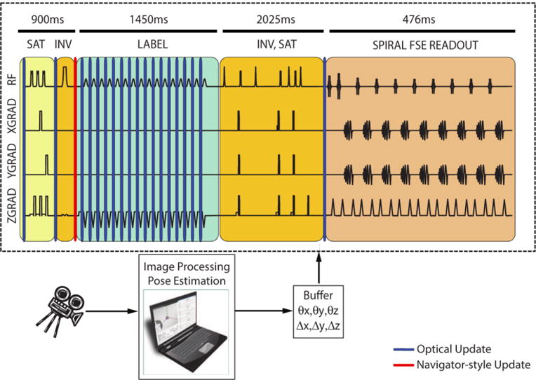
The 3D PCASL sequence used in this study and the timing of motion updates for optical and navigator-style updates. While using optical updates, the scan plane geometry was updated once before the first inversion module, continuously during the labeling module and once before the readout module. On the other hand, during navigator-style updates, motion was updated once before the labeling module using optical updates, simulating an MR navigator inserted during the idle time within the first inversion module. Dark blue and red bands show locations of optical and navigator-style updates, respectively. No correction was performed for the second saturation or inversion module since the inversion RF pulses in this section have a large slab thickness and the saturation band lies across the neck, which does not move rigidly with the head. The time axis was scaled non-linearly to show all gradient and RF pulses.
For each experiment, the volunteers were asked to perform deliberate continuous and discrete nodding and shaking motion such that their nose tip followed a “horizontal figure 8” [22]. This motion pattern was named “continuous motion”. An additional experiment was performed where the first volunteer was instructed to perform abrupt head motion once every 20 seconds. This pattern was named “discrete motion”. In the case of discrete motion, in order to cover different ranges of motion, the volunteer was instructed to move both around the R/L and S/I axis in a predetermined fashion. The 3D PCASL scan was performed four times for each of the four experiments:
No motion, no correction (to serve as reference data);
Motion, no correction;
Motion, correction using infrequent, navigator-style updates and
Motion, correction using optical updates.
The Pearson correlation coefficient between each slice of the reference scan and the scans with motion were used as a metric to quantify motion artifacts since a higher correlation coefficient implies a higher degree of similarity to the reference scan. Before the calculation of correlation coefficients, the uncorrected and corrected proton-density and ASL volumes were registered to the reference volume in order to eliminate the dependence of correlation coefficients on misregistration. This alignment was performed by first registering the proton-density-weighted volumes of each motion scan to those of the reference volume, followed by application of the registration parameters to the ASL images. This way, the correlation coefficient depended only on motion-related aliasing and blurring artifacts.
Figure 8.
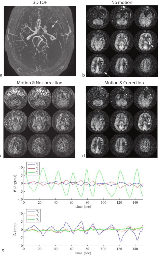
Result of continuous shaking motion in a patient with chronic steno-occlusive disease. (a) An axial MIP from a 3D TOF MRA shows absence of blood flow in the left middle cerebral artery (arrow). The patient was asymptomatic and had sufficient collateral supply but the delayed arrival of the arterial spin label can be seen as a region of decreased ASL signal in the left M1 territory tissue (b, arrow) and hyper-intense arterial signal in the left insula region (b, arrowhead). This signal abnormality was masked by motion (c), but was visible in a second measurement that included optical motion correction (d). The motion plot from the optical-corrected scan is shown in (e).
Results
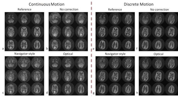
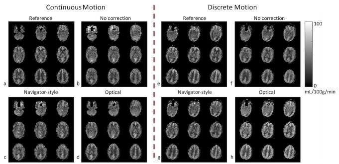
Figures 2–6 show results from the first volunteer. Similar results were obtained for the other volunteers. The raw ASL images and the CBF maps from the first volunteer are shown in Figure 2 and Figure 3, respectively. Without correction, the ASL and CBF images contain significant blurring, especially in the frontal part of the brain where the voxel displacement resulting from rotations of head is the largest (Figure 2b,f, Figure 3b,f). Due to the latency of navigator-style correction and the continuous motion performed by the volunteer (Figure 4), motion artifacts remain after navigator-style correction (Figure 2c,g, Figure 3c,g). Motion artifacts were substantially removed when optical motion correction was turned on (Figure 2d,h, Figure 3d,h). In particular, Figure 2d,h and Figure 3d,h demonstrate that the approach works at the two most critical locations, i.e. frontal brain where motion is largest and the occipital brain which is furthest away from the tracking point and where tracking errors could introduce overcorrection. Figure 4 shows the motion measured by the optical system during the scans of the first volunteer with motion and optical correction for the experiment with continuous motion (Figure 4a) and discrete motion (Figure 4b). Thus, these motion plots corresponds to data in Figure 2d,h and Figure 3d,h. Since the volunteer was trained to perform deliberate motion before the scan, the motion plots were similar for all three repeats of the motion experiments (i.e. no correction, navigator-style correction, and optical correction).
Figure 2.
ASL difference images (label-control) from the first volunteer’s scan in the presence of continuous and discrete motion. Without correction, the ASL images contain significant blurring, especially in the frontal part of the brain where the pixel-wise displacement is the largest (b,f). With navigator-style correction, the ASL images still have residual artifacts due to the delay in correction (c,g). Data corrected with optical tracking are virtually free of artifacts (d,h).
Figure 6.
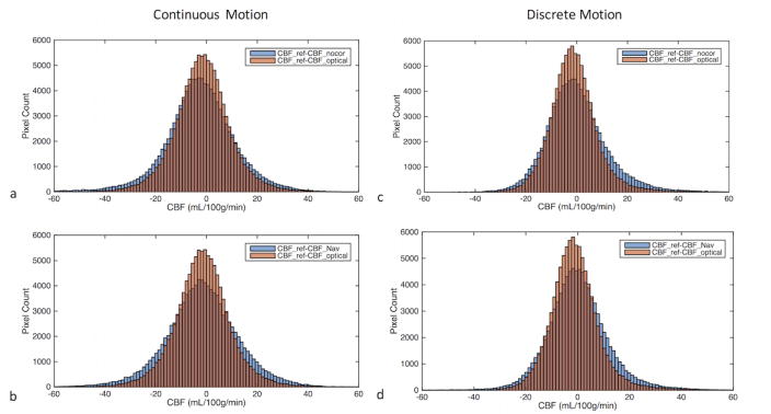
Histogram of pixel-wise differences between reference CBF and the CBF obtained from three motion experiments (i.e., non-corrected, corrected using navigator-style updates and corrected using continuous optical updates) in the presence of continuous (a,b) and discrete (c,d) motion. In order to make comparison easier, the histogram difference between CBF values obtained from the experiment with optical correction and reference (CBF_ref-CBF_optical) is plotted on the same graph with the other two CBF difference histograms (i.e., CBF_ref-CBF_nocor and CBF_ref-CBF_Nav). The intersections of the histograms are shown with a darker color. It can be seen that CBF_ref-CBF_optical histogram has a more peaked distribution than CBF_ref-CBF_nocor (a,c) or CBF_ref-CBF_Nav (b,d), implying CBF_optical values are closer to CBF_ref compared to the other two methods.
Figure 3.
CBF maps from the first volunteer’s scan in the presence of continuous and discrete motion. Without correction, the CBF maps contain significant blurring, especially in the frontal part of the brain where the pixel-wise displacement is the largest (b,f). With navigator-style correction, the CBF maps still have residual artifacts due to the delay in correction (c,g). Images corrected with optical tracking (d,h) are very similar to images with no motion (a,e).
Figure 4.
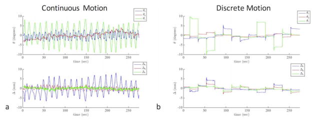
Plots of the three rotation and three translation parameters measured using the optical tracking system during the “optical correction” experiments shown in Figs. 2d,h and Fig. 3d,h. In order to provide a better visualization of the motion plots, the average of each rotation and translation plot is subtracted so that the motion plots are centered around 0.
The cross-correlation coefficients between the reference ASL scan (i.e., where the volunteer did not perform any motion task) and the three scans that were acquired while the first volunteer was performing the motion tasks are shown in Figure 5 in the presence of continuous motion (Figure 5a) and discrete motion (Figure 5b). It can be seen in Figure 5 that the correlation coefficient of the optical motion-corrected slices are higher than those of uncorrected and navigator-style-corrected slices, implying a higher similarity between the optical motion-corrected and reference datasets. In fact, in this example, in the presence of continuous motion, the ASL difference images for the case of no correction (Figure 2b) are more similar to the reference (Figure 2a) than when navigator-style (Figure 2c) correction was applied, which is also reflected in the cross-correlation coefficient (Figure 5a).
Figure 5.
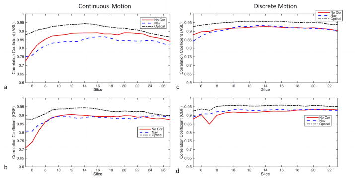
The slicewise cross-correlations between the reference (i.e. where the volunteer performed no motion) and the three ASL or CBF maps (i.e., non-corrected, corrected using navigator-style updates and corrected using continuous optical updates) corresponding to the experiments in Figs. 2 and 3. The images display the cross-correlation plots of (a) ASL images in the presence of continuous motion (b) CBF maps in the presence of continuous motion. (c) ASL images in the presence of discrete motion (b) CBF maps in the presence of discrete motion. Note that the correlation coefficients were calculated from only the middle 26 slices (out of the total 36 slices), due to the lower signal and SNR in the outer slices.
Figure 6 shows the histogram of pixel-wise differences between the reference CBF (CBF_ref) and the CBF values obtained from experiments with no correction (CBF_nocor), navigator-style correction (CBF_Nav) and optical correction (CBF_optical). It can be seen that both for continuous and discrete motion, CBF_ref-CBF_optical histogram has a more peaked appearance than CBF_ref-CBF_nocor (Figure 6a,c) or CBF_ref-CBF_Nav (Figure 6b,d), implying CBF_optical values are closer to CBF_ref compared to the other two methods. For these experiments, the standard deviations of CBF_ref-CBF_nocor, CBF_ref-CBF_Nav and BF_ref-CBF_optical were 14.28, 14.35 and 11.09 mL/100g/min for continuous motion, and they were 12.42, 12.04 and 9.60 mL/100g/min for discrete motion respectively.
Figure 7 shows the slicewise cross-correlation coefficients from all three volunteers in the presence of continuous motion. In this figure, the pairwise differences of the correlation coefficients between uncorrected, navigator-style-corrected and optical motion-corrected slices are shown using box-and-whisker plots. For each boxplot, the center of the box represents the median and the edges the 25th and 75th percentiles. The whiskers indicate range of correlation values that were not considered to be outliers. The data points outside the +/−2.7σ coverage were considered outliers. The difference between optical motion correction and the other two methods is greater than 0, implying improved image quality over all three volunteers. On the other hand, little difference was observed between uncorrected and navigator-style-corrected experiments (Figure 7).
Figure 7.
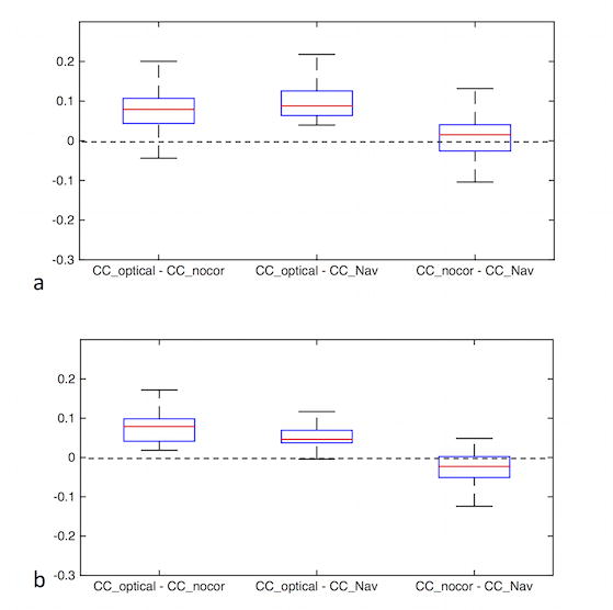
Combined results of correlation coefficients from three volunteers in the presence of continuous motion for ASL difference images (a) and CBF maps (b). The distributions of pairwise difference between slicewise correlation coefficients of different methods (i.e., no correction, navigator-style correction, optical correction) are shown. The difference between optical motion correction and the other two methods is greater than 0, implying an improved image quality over all three volunteers.
Figure 8 shows an example from a subject suffering from chronic steno-occlusive disease of the left middle cerebral artery that resulted in delayed arterial label arrival in the left M1 territory (Figure 8a, b white arrow). The low ASL signal in this area is not due to reduced blood flow but rather due to delayed label arrival time, which can be seen from the hyperintense arterial transit artifacts. In this 3D PCASL exam, the subject was moving his head within a range of approximately 15°. Without correction, the ASL images were non-diagnostic and the region of low ASL signal was undetectable. When adaptive motion correction was turned on, the motion artifacts were mostly eliminated and the region of low ASL signal was visible (Figure 8d). Figure 8e shows the motion plot from the corrected scan (the volunteer performed a similar motion during the non-corrected scan). No navigator-style experiment was performed for this subject.
Discussion
Prospective motion correction systems that employ cameras to track and correct for head motion have several advantages over conventional navigator-based methods. One of these advantages is the applicability of prospective optical motion correction to any pulse sequence without requiring any changes in the sequence timing. This is especially important for pulse sequences that do not contain any idle time for the insertion of a navigator echo. Although 3D PCASL is a long-TR sequence with ample time between label module and data readout, there are only few gaps where a navigator echo can practically be inserted. This may seem paradoxical, but the problem arises because at the time the image readout occurs, background suppression prevents one from acquiring navigator echoes with substantial signal. Therefore, in [13], three orthogonal navigator spiral readouts were inserted right after the saturation pulse, and, in [23], a 3D volumetric EPI readout was inserted before the second background suppression pulse. In both cases, there was a clearly a substantial delay between the determination of motion and the application of corrective measures to the readout portion of the sequence, which is suboptimal, but unavoidable. Note that, even with this delay, navigator-based correction has been shown to work well in the presence of infrequent abrupt motion [13]. Navigator-based correction can also be expected to work well in the presence of slow drifting motion. However, for more frequent motion patterns, rescanning is necessary to ensure that the most up-to-date motion parameters are used for each segment of the readout, which in turn increases scan time [13]. Thus, in situations where patients are restless for the entire exam, it is therefore essential that the latency of motion detection and correction should be as low as possible for best image quality and shortest scan time. Fast continuous motion patterns can be observed within patient populations with certain medical conditions, such as Parkinson’s disease, dementia, or stroke. The experiments and techniques in this study were designed to demonstrate the effect of latency in these cases of restless motion throughout the entire exam.
The comparison between optical and navigator-style correction was only performed to demonstrate the effects of latency, and other factors such as imperfections in registration, B0 shifts due to gradient heating, etc. were ignored. Also note that no rescanning was done in the case of navigator-style correction. As stated above, rescanning increases the scan time, and given long TR times and the presence of continuous motion, the increase in scan time can be prohibitive even though the final images are high quality. Thus, in order to make a fair comparison, we did not apply rescanning for any of the motion experiments.
In [24], the application of an optical system to ASL perfusion imaging was mentioned in the context of a novel stereovision system for head motion correction; however, only preliminary ASL imaging results were presented in short abstract form. In this study, we demonstrated the application of an optical tracking system to 3D PCASL perfusion imaging, and compared it to navigator-style approach. Specifically, we applied a low-latency, monovision-based optical tracking system to a background-suppressed, pseudo-continuous arterial spin label sequence with interleaved 3D spiral-FSE readouts. Our results using quasi-continuous motion correction based on optical tracking demonstrated a substantial improvement in image quality and quantitative results when compared to navigator-style motion corrected or uncorrected 3D PCASL in the presence of motion (Figure 5,Figure 7). One important observation was that, for the experiment with continuous motion, navigator-style corrections did not improve the image quality over the non-corrected images (Figure 2c, Figure 3c, Figure 5a,b, Figure 6a,b). This was due to the specific motion pattern used: The period of motion was around T=~10 seconds. This means that significant displacement occurred within ~5 seconds (=T/2). Because the latency was ~3–4 seconds in navigator style correction, the head displacement was quite high between the time the motion was corrected and spiral readout being acquired. Note that this was not the case in “discrete-motion” experiment – the navigator-style-corrected images were better than non-corrected ones (but still worse than optical corrected images) (Figure 2h, Figure 3h, Figure 5c,d, Figure 6c,d).
The results also demonstrated that motion in 3d PCASL perfusion imaging can obscure potential blood flow abnormalities even if they affect a large vascular territory (Figure 8a,b,c), and that application of prospective correction using optical motion tracking can shift the image quality from a non-diagnostic to diagnostic study (Figure 8d). This is important, as it allows the radiologist to render a diagnosis without the need for a repeat scan or calling a patient back.
One potential shortcoming of optical prospective motion correction is that it is necessary to perform scanner-camera cross-calibration in order to convert motion estimates acquired in the camera frame into those in scanner coordinates. This can potentially add extra time for setup to the scan session. However, this is not the case for our setup: the cross-calibration is performed once when the camera is first installed, and involves the use of a special calibration tool with inductively coupled microcoils [25,26]. Later, when a specific volunteer/patient is to be scanned, this previous online cross-calibration calibration is read from file. Any changes in scanner table position due to different landmarks and FOV prescriptions are read from table encoder and the cross-calibration is updated accordingly. Thus, after an initial offline calibration step, no additional setup time is required for each volunteer/patient. This method requires that the coil and camera can be mounted on the same location for different scan sessions. This is satisfied in our setup by having coil and camera mounts that are specifically constructed to snugly fit in the same location with sub-millimeter tolerance. This cross-calibration technique was found to be sufficient for high-quality optical motion correction [27].
An important requirement for optical prospective motion correction is that the line-of-sight between the camera and the marker needs to be established at all times for motion tracking to occur. The large gaps between coil rungs in the 8-channel head coil used in this study helps to maintain the line-of-sight that is required for optical tracking to work. However, even for coils with large gaps between coil rungs, a standard optical marker can be obstructed or partly leave the camera field-of-view [28]. Reasons for this include changes in initial marker placement and/or patient positioning, patient drifting during scan, or patient head being large such that the marker is very close to the camera. The self-encoded marker used in this study is designed to overcome these issues and ensure that the motion can be tracked even with a partial view of the marker. However, more advanced coils have higher number of channels and thus have limited to no gap for the camera to look through, which will make establishing line-of-sight more difficult. In this case, one method could be to insert the camera directly into the plastic housing of the coil. Since the marker can be tracked even with a partial view, only a small hole between coil elements would be sufficient to track head motion.
Another important consideration is that the marker needs to be attached rigidly to the subject’s forehead. Any motion of the marker independent of the head introduces false corrections, which might occur due to skin motion. Fortunately, our setup was robust to skin motion: The size of the marker we used was 89×39 mm, had 2 mm thickness and was attached to the forehead using double-sided medical tape. The relatively large size of the marker provided multiple attachment points to the forehead, thus making motion tracking robust to skin motion. Additionally, we tested this system at our hospital and research center on multiple tumor, stroke, metastasis, AD and dementia patients, none of whom reported any inconvenience due to the existence of the marker.
It is also important that an optical tracking system has high precision (i.e., low noise in detected motion data) so that no false corrections are introduced [29]. Owing to the 3D shape of the marker and with the addition of custom denoising and image processing algorithms, even the noise in through-plane rotations and translations are well-below 1mm and degree in scanner coordinates. Specifically, for one of the non-motion scans in this manuscript, the standard deviation of rotations and translations were measured to be ~0.1 degree and mm. For this study and for all the other experiments we have performed using this system (including standard imaging techniques such as fast-spin-echo, T1 and T2 FLAIR, 3D time-of-flight, 3D gradient echo, T1 spin-echo, etc.), the motion correction did not introduce any false corrections, i.e., the corrected and non-corrected scans looked very similar in the absence of any deliberate motion.
Acknowledgments
The authors acknowledge grant support by NIH (5R01EB011654, 5R01EB008706, 5R01EB002711, P41 RR009784, P41EB015891) and the Lucas Foundation.
Footnotes
Publisher's Disclaimer: This is a PDF file of an unedited manuscript that has been accepted for publication. As a service to our customers we are providing this early version of the manuscript. The manuscript will undergo copyediting, typesetting, and review of the resulting proof before it is published in its final citable form. Please note that during the production process errors may be discovered which could affect the content, and all legal disclaimers that apply to the journal pertain.
References
- 1.Williams DS, Detre JA, Leigh JS, Koretsky AP. Magnetic resonance imaging of perfusion using spin inversion of arterial water. Proc Natl Acad Sci USa. 1992;89:212–6. doi: 10.1073/pnas.89.1.212. [DOI] [PMC free article] [PubMed] [Google Scholar]
- 2.Detre JA, Zhang W, Roberts DA, Silva AC, Williams DS, Grandis DJ, et al. Tissue specific perfusion imaging using arterial spin labeling. NMR Biomed. 1994;7:75–82. doi: 10.1002/nbm.1940070112. [DOI] [PubMed] [Google Scholar]
- 3.Alsop DC, Detre JA. Multisection cerebral blood flow MR imaging with continuous arterial spin labeling. Radiology. 1998;208:410–6. doi: 10.1148/radiology.208.2.9680569. [DOI] [PubMed] [Google Scholar]
- 4.Wu W-C, Fernández-Seara M, Detre JA, Wehrli FW, Wang J. A theoretical and experimental investigation of the tagging efficiency of pseudocontinuous arterial spin labeling. Magnetic Resonance in Medicine. 2007;58:1020–7. doi: 10.1002/mrm.21403. [DOI] [PubMed] [Google Scholar]
- 5.Pollock JM, Tan H, Kraft RA, Whitlow CT, Burdette JH, Maldjian JA. Arterial spin-labeled MR perfusion imaging: clinical applications. Magn Reson Imaging Clin N Am. 2009;17:315–38. doi: 10.1016/j.mric.2009.01.008. [DOI] [PMC free article] [PubMed] [Google Scholar]
- 6.Alsop DC, Detre JA, Golay X, Günther M, Hendrikse J, Hernandez-Garcia L, et al. Recommended implementation of arterial spin-labeled perfusion MRI for clinical applications: A consensus of the ISMRM perfusion study group and the European consortium for ASL in dementia. Magnetic Resonance in Medicine. 2015;73:102–16. doi: 10.1002/mrm.25197. [DOI] [PMC free article] [PubMed] [Google Scholar]
- 7.Dai W, Garcia D, de Bazelaire C, Alsop DC. Continuous flow-driven inversion for arterial spin labeling using pulsed radio frequency and gradient fields. Magnetic Resonance in Medicine. 2008;60:1488–97. doi: 10.1002/mrm.21790. [DOI] [PMC free article] [PubMed] [Google Scholar]
- 8.Dixon WT, Sardashti M, Castillo M, Stomp GP. Multiple inversion recovery reduces static tissue signal in angiograms. Magnetic Resonance in Medicine. 1991;18:257–68. doi: 10.1002/mrm.1910180202. [DOI] [PubMed] [Google Scholar]
- 9.Ye FQ, Frank JA, Weinberger DR, McLaughlin AC. Noise reduction in 3D perfusion imaging by attenuating the static signal in arterial spin tagging (ASSIST) Magnetic Resonance in Medicine. 2000;44:92–100. doi: 10.1002/1522-2594(200007)44:1<92::aid-mrm14>3.0.co;2-m. [DOI] [PubMed] [Google Scholar]
- 10.Maleki N, Dai W, Alsop DC. Optimization of background suppression for arterial spin labeling perfusion imaging. Magma. 2012;25:127–33. doi: 10.1007/s10334-011-0286-3. [DOI] [PMC free article] [PubMed] [Google Scholar]
- 11.Garcia DM, Duhamel G, Alsop DC. Efficiency of inversion pulses for background suppressed arterial spin labeling. Magnetic Resonance in Medicine. 2005;54:366–72. doi: 10.1002/mrm.20556. [DOI] [PubMed] [Google Scholar]
- 12.Alsop D, Detre J. Background suppressed 3D RARE ASL perfusion imaging. International society for magnetic resonance in …. 1999 [Google Scholar]
- 13.Zun Z, Shankaranarayanan A, Zaharchuk G. Pseudocontinuous arterial spin labeling with prospective motion correction (PCASL-PROMO) Magnetic Resonance in Medicine. 2014;72:1049–56. doi: 10.1002/mrm.25024. [DOI] [PMC free article] [PubMed] [Google Scholar]
- 14.White N, Roddey C, Shankaranarayanan A, Han E, Rettmann D, Santos J, et al. PROMO: Real-time prospective motion correction in MRI using image-based tracking. Magnetic Resonance in Medicine. 2010;63:91–105. doi: 10.1002/mrm.22176. [DOI] [PMC free article] [PubMed] [Google Scholar]
- 15.Zaitsev M, Dold C, Sakas G, Hennig J, Speck O. Magnetic resonance imaging of freely moving objects: prospective real-time motion correction using an external optical motion tracking system. Neuroimage. 2006;31:1038–50. doi: 10.1016/j.neuroimage.2006.01.039. [DOI] [PubMed] [Google Scholar]
- 16.Aksoy M, Forman C, Straka M, Skare S, Holdsworth S, Hornegger J, et al. Real-time optical motion correction for diffusion tensor imaging. Magnetic Resonance in Medicine. 2011;66:366–78. doi: 10.1002/mrm.22787. [DOI] [PMC free article] [PubMed] [Google Scholar]
- 17.Maclaren J, Armstrong BSR, Barrows RT, Danishad KA, Ernst T, Foster CL, et al. Measurement and Correction of Microscopic Head Motion during Magnetic Resonance Imaging of the Brain. PLoS ONE. 2012;7:e48088. doi: 10.1371/journal.pone.0048088. [DOI] [PMC free article] [PubMed] [Google Scholar]
- 18.Schulz J, Siegert T, Reimer E, Labadie C, Maclaren J, Herbst M, et al. An embedded optical tracking system for motion-corrected magnetic resonance imaging at 7T. Magma. 2012;25:443–53. doi: 10.1007/s10334-012-0320-0. [DOI] [PubMed] [Google Scholar]
- 19.Forman C, Aksoy M, Hornegger J, Bammer R. Self-encoded marker for optical prospective head motion correction in MRI. Med Image Anal. 2011;15:708–19. doi: 10.1016/j.media.2011.05.018. [DOI] [PMC free article] [PubMed] [Google Scholar]
- 20.Aksoy M, Maclaren JR, Ooi MB, Ehrl J, Aksoy D, Zun Z, et al. Prospective Optical Motion Correction for 3D Pseudo-continuous Arterial Spin Labeling Proceedings of the joint annual meeting of ISMRM-ESMRMB. Proceedings of the Joint Annual Meeting of ISMRM-ESMRMB; Milan, Italy. 2014. p. 424. [Google Scholar]
- 21.Herbst M, Maclaren JR, Weiger M, Zaitsev M. Investigation and continuous correction of motion during turbo spin echo sequences Proceedings of the 20th Annual Meeting of ISMRM. Proceedings of the 20th Annual Meeting of ISMRM; Melbourne, Australia. 2012. p. 596. [Google Scholar]
- 22.Herbst M, Maclaren J, Weigel M, Korvink J, Hennig J, Zaitsev M. Prospective motion correction with continuous gradient updates in diffusion weighted imaging. Magnetic Resonance in Medicine. 2012;67:326–38. doi: 10.1002/mrm.23230. [DOI] [PubMed] [Google Scholar]
- 23.van der Kouwe A, Tisdall D, Bhat HR, Heberlein K. Prospective motion correction of 3D GRASE PASL acquisitions with volume navigators Proceedings of the 21st Scientific Meeting of ISMRM. Proceedings of the 21st Scientific Meeting of ISMRM; Salt Lake City, UT. 2013. p. 3030. [Google Scholar]
- 24.Hoßbach M, Gregori J, Wesarg S, Günther M. Head Motion Compensation for Arterial Spin Labeling Using Optical Motion Tracking, SPIE, Lake Buena Vista. Florida, US: Springer; 2013. p. 86682E. [Google Scholar]
- 25.Ooi MB, Aksoy M, Maclaren J, Watkins RD, Bammer R. Prospective motion correction using inductively coupled wireless RF coils. Magnetic Resonance in Medicine. 2013;70:639–47. doi: 10.1002/mrm.24845. [DOI] [PMC free article] [PubMed] [Google Scholar]
- 26.Maclaren JR, Ooi MB, Aksoy M, Ehrl J, Bammer R. Calibration and Quality Assurance for Optical Prospective Motion Correction Using Active Markers Proceedings of the joint annual meeting of ISMRM-ESMRMB. Proceedings of the Joint Annual Meeting of ISMRM-ESMRMB; Milan, Italy. 2014. p. 4340. [Google Scholar]
- 27.Maclaren J, Aksoy M, Zahneisen B, Bammer R. Camera Placement for Optical Prospective Motion Correction: Mechanical Tolerance Analysis. Proceedings of the 23rd Scientific Meeting of ISMRM; Toronto, Canada. 2015. p. 3669. [Google Scholar]
- 28.Singh A, Zahneisen B, Keating B, Herbst M, Chang L, Zaitsev M, et al. Optical tracking with two markers for robust prospective motion correction for brain imaging. Magma. 2015;28:523–34. doi: 10.1007/s10334-015-0493-4. [DOI] [PMC free article] [PubMed] [Google Scholar]
- 29.Maclaren J, Speck O, Stucht D, Schulze P, Hennig J, Zaitsev M. Navigator accuracy requirements for prospective motion correction. Magnetic Resonance in Medicine. 2010;63:162–70. doi: 10.1002/mrm.22191. [DOI] [PMC free article] [PubMed] [Google Scholar]


