Significance
Acoustic communication is critical for underwater application such as deep-ocean scientific explorations and off-shore industrial controls. This is because other techniques using electromagnetic waves are difficult for underwater applications due to the strong absorption of water. Optical communication, on the other hand, suffers from the light scattering, making long-range underwater optical communication very challenging. Therefore, using acoustic waves to transmit information is currently the dominant technique for underwater applications. However, the low-frequency bandwidth available limits the data transmission rate and information capacity. We propose and experimentally demonstrate an approach using the orbital angular momentum (OAM) of acoustic vortex beams, which provides an independent channel that enhances the data transmission rate. This OAM multiplexing method will significantly impact future underwater communications.
Keywords: high-speed acoustic communication, high spectral efficiency, orbital angular momentum, multiplexing, demultiplexing
Abstract
Long-range acoustic communication is crucial to underwater applications such as collection of scientific data from benthic stations, ocean geology, and remote control of off-shore industrial activities. However, the transmission rate of acoustic communication is always limited by the narrow-frequency bandwidth of the acoustic waves because of the large attenuation for high-frequency sound in water. Here, we demonstrate a high-throughput communication approach using the orbital angular momentum (OAM) of acoustic vortex beams with one order enhancement of the data transmission rate at a single frequency. The topological charges of OAM provide intrinsically orthogonal channels, offering a unique ability to multiplex data transmission within a single acoustic beam generated by a transducer array, drastically increasing the information channels and capacity of acoustic communication. A high spectral efficiency of 8.0 ± 0.4 (bit/s)/Hz in acoustic communication has been achieved using topological charges between −4 and +4 without applying other communication modulation techniques. Such OAM is a completely independent degree of freedom which can be readily integrated with other state-of-the-art communication modulation techniques like quadrature amplitude modulation (QAM) and phase-shift keying (PSK). Information multiplexing through OAM opens a dimension for acoustic communication, providing a data transmission rate that is critical for underwater applications.
With the increasing amount of human activities underwater including unmanned vehicle exploration, off-shore industrial applications, and remote ocean environment monitoring, the development of underwater communication has become essential. The intrinsic strong absorption of microwave and mid- and far-infrared radiations by water molecules limits the propagation distance of radio frequencies to mere centimeters (1–4), making rf wireless communication approaches impossible. On the other hand, optical waves are scattered by objects in the ocean such as small particles, debris, and marine life due to the shorter wavelengths, limiting the range of optical communication underwater to be within just 200 m (5–7). Presently, acoustic waves are the only option for long-range (over 200 m) underwater communications. However, the applicable bandwidth of acoustic waves is limited within 20 kHz because the higher damping loss of high-frequency acoustic waves in water reduces the propagation distance to less than a kilometer range (8). Such a low carrier frequency limits drastically the spectral bandwidth and data rate accessible for data transmission. Although spectral efficiency has been improved through recent advanced communication technologies such as differential phase-shift keying (PSK) and quadrature amplitude modulation (QAM), the number of available data transmission channels remains tied to the low carrier frequency (9–13).
We propose to overcome such a fundamental limitation in acoustic communication by using additional spatial degrees of freedom for data transmission, such as orbital angular momentum (OAM) of the information-carrying wave whose wavefront has helical patterns (i.e., vortex beams). This spatial degree of freedom increases the data transmission capacity, which is given by the product of the available frequency bandwidth and number of modes used for communication, at the same frequency band. In optics and microwaves, vortex or helical beams with different OAM topological charges are generated by spatial light modulator, metasurfaces, or parity-time symmetric ring resonator and multiplexed through beam splitters or spin–orbital coupling to demonstrate a significant increase of data transmission capability (14–19). For acoustics, the underwater propagation of vortex beams with single topological charge was demonstrated with active phase arrays (20, 21). Passive acoustic phase modulation structures were proposed to generate single-charge vortex beams (22–25). These acoustic vortex beams were used to develop acoustic tweezers, and screwdrivers for particle trapping, levitation, and manipulations (26–30). However, information encoding through multiple OAM channels multiplexing/demultiplexing remains unexplored. Here, we demonstrate that the data transmission rate can be dramatically enhanced at a single frequency modulation by using the spatial degree of freedom OAM of acoustic vortex beams. The proposed high-throughput acoustic communications with OAM multiplexing are experimentally demonstrated in air here due to the facility limitations in underwater acoustics, but this technique can be readily extended to underwater applications because the wave physics in air and underwater are the same for low-frequency acoustics below 20 kHz. In addition, previous studies have experimentally demonstrated the long-distance propagation of phase information of underwater acoustic wave, crucial to underwater communications using OAM multiplexing (11, 20, 21). Note that the spatial multiplexing proposed can be added onto or combined with existing frequency-encoding techniques (PSK, QAM, etc.). Thus, this degree of freedom has the ability to further increase the existing highest acoustic underwater communication rate by N-fold, with N the number of OAM channels used.
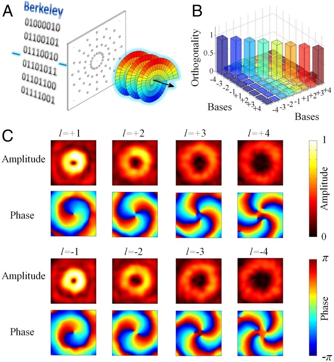
We use an active transducer array controlled by a digital processor to directly generate multiplexed acoustic vortex beams with 8 OAM charges from −4 to +4 (Fig. 1A). Beam splitter or spin–orbital coupling was used for multiplexing different OAM topological charges in optics and microwaves (14–19). However, acoustic beam splitter is still a challenging research topic (31) and the circular polarization of spin is fundamentally unavailable for sound waves. In our experiment, the multiplexing of different OAM charges is achieved by directly generating the interference pattern of the corresponding vortex beams, which requires independent modulations of amplitude and phase (Fig. S1). For each OAM topological charge l, the array as the sound source generates a relative phase difference varying from 0 to 2lπ along the azimuthal direction. The amplitudes and phases measured at 100 wavelengths away from the emitting plane for vortex beams with OAM charges −4 to +4 at 16 kHz are shown in Fig. 1C. A low-pass spatial filter is applied to remove the high-frequency noise in the measured fields. The number of twists in the phase pattern indicates the magnitude of the OAM charge. The amplitude pattern of each vortex beam presents a ring shape with increasing radius as the magnitude of the topological charge becomes larger. We calculate the orthogonality relation between vortex beams with different OAM charges (Fig. 1B) by taking the inner product of the two corresponding pressure fields incorporating both amplitudes and phases (Generation of Acoustic Vortex and Multiplexed Beams). The cross-talk of the measured vortex beams shown in Fig. 1C is less than −8.54 dB. Therefore, these eight vortex beams provide orthogonal bases to increase the number of the physical channels for data transmission.
Fig. 1.
Acoustic communication using vortex beams with OAM charges −4 to +4. (A) Experimental setup of acoustic communication with vortex beams. A computer-controlled digital-to-analog circuit generates signal to control 4 rings of transducers (with 16 transducers equally spaced on each ring) and emit information encoded into multiplexed acoustic vortex beams into free space at 16 kHz. The radii of these 4 rings are 3, 6, 9, and 12 wavelengths. (B) Measured orthogonality relations between the bases formed by acoustic vortex beams with OAM charges −4 to +4. Each of the bars is calculated by forming the inner products between the measured pressure fields of the two corresponding bases. The norm of each basis is normalized to unity. The cross-talk between the bases is less than −8.54 dB. (C) Measured pressure-field amplitudes and phases of acoustic vortex beam bases with OAM charges −4 to +4 at 100 wavelengths (2.14 m) away from the emitting plane in air. The scanning area covers 22.4 wavelengths by 22.4 wavelengths (48 cm × 48 cm) with 26 by 26 resolutions. Thermal and rainbow-scale color bars are used for the measured amplitude and phase fields, respectively.
Fig. S1.
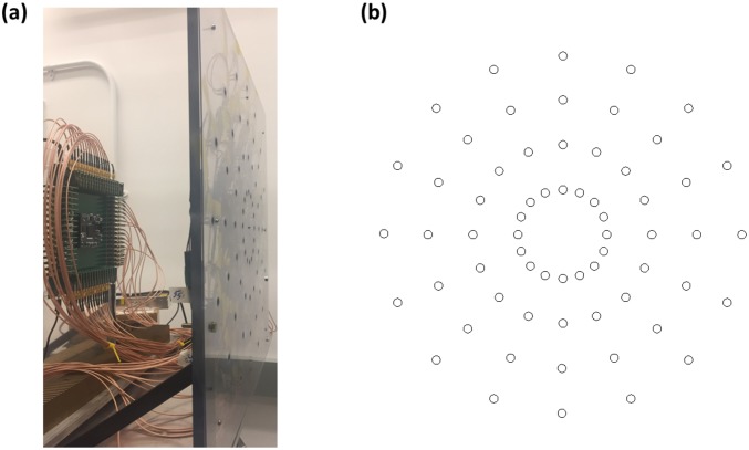
Active phase array used in our experiment. (A) Experimental setup. The digital processor on the left drives the speakers mounted on the plastic frame. (B) Pattern of the emitting array containing 64 speakers. Each circle represents a speaker. These speakers form 4 rings with radii 3, 6, 9, and 12 wavelengths. Each ring contains 16 equally spaced speakers.
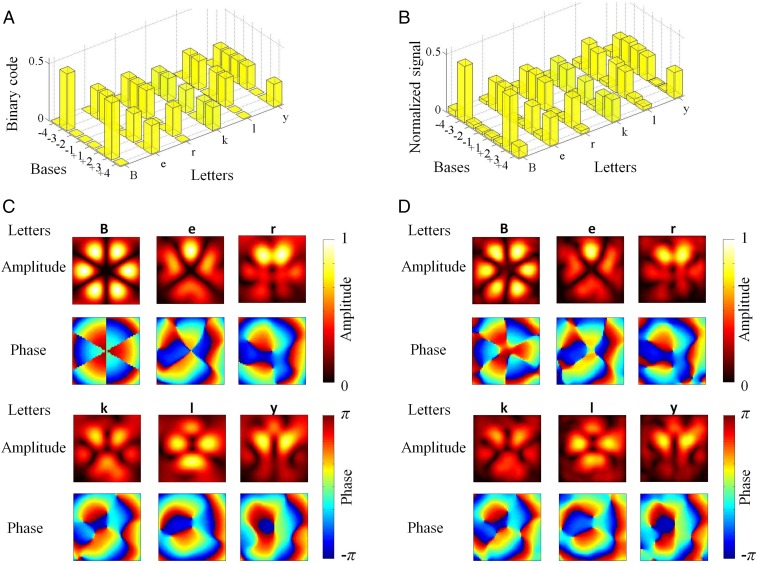
The multiplexing of the orthogonal OAM charges allows parallel information to be sent through a single acoustic beam. This multiplexing procedure is accomplished in the digital processor by forming linear combinations of the vortex signals used to generate the OAM bases in Fig. 1C. The resulting signals are sent to the active transducer array to emit the information-encoded multiplexed beam. Because the acoustic beam can be encoded with up to eight orthogonal OAM bases in our setup (Fig. 1), a single acoustic beam conveys a byte (8 bits) of information. In our experiment, we use the multiplexed OAM beams to send the word “Berkly,” which is represented in ASCII binary protocol (Fig. 2A). Each OAM charge represents 1 bit of information in the 1-byte binary symbols of the letters. The OAM charges corresponding to “1” in the binary representations are called on-channels, and the other charges are off-channels. Because the multiplexed signals are emitted by the single transducer array, we set the total amplitude of each 1-byte letter to be the same, i.e., the total amplitude is equally distributed among all of the on-channels for each letter. The inner product method used to characterize the cross-talk between the bases in Fig. 1B provides an elegant method to decode the information from the superimposed multiplexed beams (Fig. 2 C and D). We use the measured pressure fields (including amplitude and phase) of the letters in Fig. 2D to perform inner products with the eight-bases set in Fig. 1C. The calculated signals obtained experimentally from the receiver side are shown in Fig. 2B, matching well with the binary representations in Fig. 2A. Therefore, the word Berkly is sent through multiplexed acoustic vortex beams with OAM charges −4 to +4 at the same frequency. This multiplexing method provides an extra dimension for information encoding in acoustic communications and increases the data transmission rate for all binary information and files.
Fig. 2.
Experimental demonstration of acoustic communication using multiplexed acoustic vortex beams. (A) Binary (ASCII) representations of the letters in the word Berkly. Each letter contains 8 bits (1 byte) of information. Each byte contains the same amount of total amplitude, i.e., the signal bars in each letter sum up to unity. This amplitude amount is equally distributed into the vortex beams forming the multiplexed signal. A multiplexed beam formed by the eight orthogonal vortex beams with OAM charges −4 to +4 is capable to convey the information of each letter. (B) Measured signals of the letters in the word Berkly. The bars are calculated by forming the inner product between the measured pressure fields of the multiplexed signal and the bases. The norms of the bases are normalized to unity. As in A, each letter contains the same amount of total amplitude, which is equally distributed in the on-channels when sending. (C) Calculated pressure-field amplitudes and phases of the multiplexed signal of the letters in the word Berkly. The field patterns of the letters are superimposed so that one cannot judge the information without demultiplexing through the inner product. (D) Measured pressure-field amplitudes and phases of the multiplexed signal of the letters in the word Berkly. The experimental results match with the calculated fields in C. Colored scale bars are used for the amplitude and phase fields, respectively.
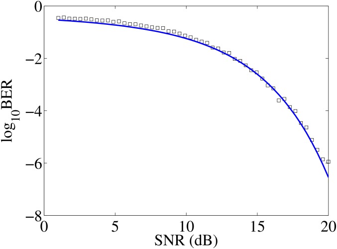
Bit error rate (BER) is a standard statistical criterion to characterize the performance of a communication system. In our experiment, the BER is calculated statistically from the measured pressure fields of the 256 possible combinations of the 8 bases (Fig. S2). For the present communication system, with 26 × 26-resolution receiver array, the BER is 10−6.5 at a 20-dB signal-to-noise ratio (SNR) level, indicating that the OAM communication is reliable. To further characterize the performance of our communication system, we vary the SNR of the input signal generated from the digital processor and measure the effect on the BER. The BER increases as the SNR becomes smaller (Fig. 3). The BER and SNR exhibit the relation (Fig. 3B), where is the signal energy associated with each user data bit and is the noise spectral density. The energy per bit to noise power spectral density ratio is given by the ratio between SNR and spectral efficiency (32, 33). Thus, the spectral efficiency of our communication system is 8.0 ± 0.4 (bit/s)/Hz, which can be further increased by using more OAM charges in the data transmission process. Such high spectral efficiency is achieved without applying other modulation techniques. Indeed, this spatial OAM degree of freedom is compatible with other acoustic communication technology. Therefore, the use of our OAM multiplexing method will increase the data transmission rate of the cutting-edge acoustic communication systems by 8×. In addition, short acoustic pulses can be applied to further increase the communication speed (Figs. S3 and S4).
Fig. S2.
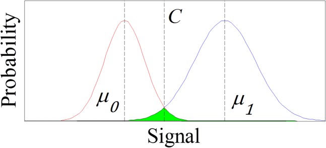
Method used for BER calculation. The two curves are Gaussian with average and and SD and for on- (blue) and off- (red) channels, respectively. C is the crossing of the two curves and is set as the criterion to judge if the signal is on or off. The error bits are on-channels below C and off-channels above C. The BER is given by the ratio of the green area and the area below the two curves.
Fig. 3.
Measured BER versus SNR of acoustic OAM communication with 26 × 26 sensor array used in the receiver. The squares are measured data with all bytes having the same total amplitude, which is equally distributed in the on-channels of the byte. The BER decreases with increasing SNR. At 20-dB SNR level, the BER is 10−6.5, which is smaller than the FEC limit and can still be corrected by standard FEC approaches (34), confirming that our communication system with acoustic OAM is reliable. The blue curve is a regression curve of the experimental data. The measured results fit with this regression curve, , indicating the spectral efficiency to be 8.0 ± 0.4 (bit/s)/Hz. The theoretical limit of the spectral efficiency is given by the number of orthogonal channels used for data transmission, which in this case is 8 bit/s/Hz. Therefore, our acoustic communication device with 8 OAM charges used for information encoding is already working at the theoretical limit.
Fig. S3.
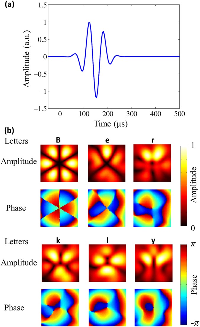
Full wave simulation of acoustic communication with OAM multiplexing with three-cycle pulse. (A) Pulse profile of the three-cycle pulse used for simulation. (B) Obtained amplitude and phase patterns for the word Berkly using the two-cycle pulse for communication.
Fig. S4.
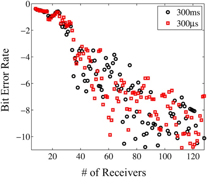
BER, which characterizes the communication performance of the system, with varying number of receivers for the two integration time intervals. It can be seen that the BER performances for these two cases are the same.
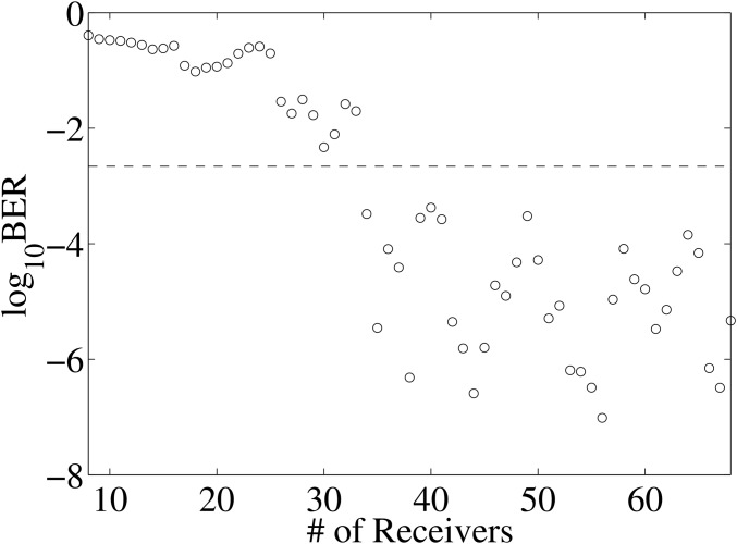
A receiver array with fewer sensors is usually desired for practical communications. To provide a design guideline for receiver arrays, we perform a down-sampling experiment to study the effect of receiver resolution on the communication performance. The receiver array contains sensors forming a 4-ring pattern with the number of microphones reducing from 68 to 8 (Fig. S5). The decreasing resolution increases the BER of the communication system (Fig. 4). A receiver array with 34 sensors results in , marking the forward error correction (FEC) limit (34). Communication errors below this limit can be corrected with standard FEC methods (34). The BER of a system with 68 sensors for the identical byte total amplitude case is 10−6.3. Further increasing the number of sensors in the receiver array does not have a significant improvement in the BER (Fig. 4). Thus, an optimized design of receiver array for practical applications can be realized by minimizing the number of sensors at the specified BER performance requirement.
Fig. S5.
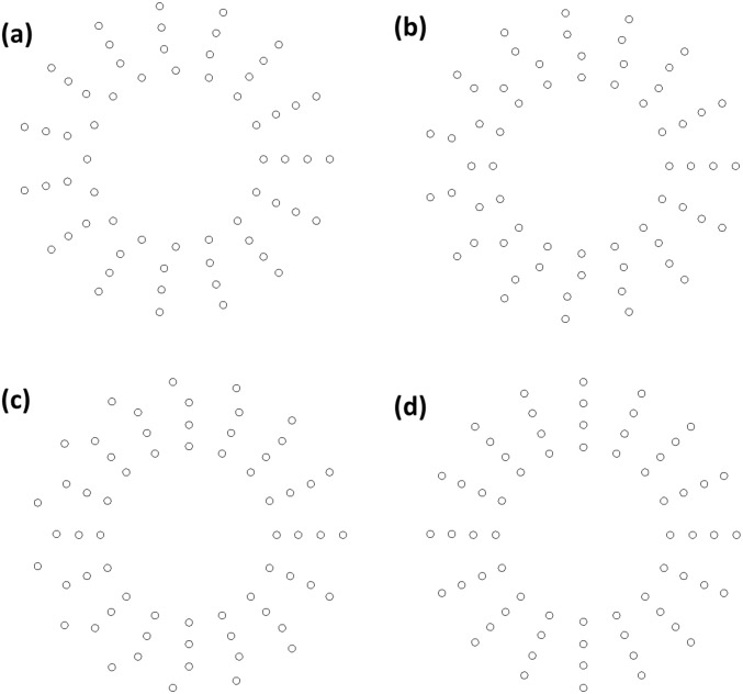
Examples of receiver arrays used to measure the BER versus SNR response. Each circle represents a microphone. The array contains (A) 61, (B) 62, (C) 63, and (D) 64 microphones. These microphones form 4 rings with radii 5.4, 6.7, 8, and 9.3 wavelengths. For an array with n = 4n + r (where n and r are integers and r < 4) sensors, the inner r rings have n + 1 equally spaced sensors and the outer 4 − r rings have n equally spaced sensors.
Fig. 4.
Measured BER dependence of number of sensors. The circles are measured data with all bytes having the same total amplitude, which is equally distributed in the on-channels of the byte. The BER decreases with increasing number of sensors in the receiver array from 8 to 68 microphones with the pattern of the array shown in the Fig. S5. The dashed line marks the FEC limit which determines the maximum error rate that can still be corrected by standard FEC approaches, which is (34). This BER limit corresponds to a minimal required receiver array with 34 sensors in our experiment. Further increasing the number of receivers will not improve the BER significantly.
In conclusion, orthogonal acoustic vortex beams with different OAM topological charges provide more physical channels for information transmission. The direct multiplexing approach used in this paper demonstrates the possibility of high-speed acoustic communications using OAM. The spectral efficiency of our experiment with OAM charges between −4 and +4 reaches 8.0 ± 0.4 (bit/s)/Hz, which is among the highest existing acoustic communication systems (9–13), and can be further increased by using more topological charges for data encoding. The OAM signal is readily demultiplexed using an inner product algorithm on the receiver side. The BER analysis confirms the reliability of acoustic communication with OAM, even with a reduced amount of receivers. This OAM communication method provides an independent basis for high-throughput acoustic information exchange and data transmission, which can be readily extend to underwater environments where acoustics is the only method for long-range sensing and communications.
Generation of Acoustic Vortex and Multiplexed Beams
The acoustic emitting plane in our experiment contains four rings of emitters (Fig. S1). Each ring consists of 16 equally spaced speakers. The radii of the rings are 3, 6 9, and 12 wavelengths. The relative phases of the speakers used to emit acoustic vortex beam with OAM topological charge l are , where is the azimuthal angle between the speaker and reference. All speakers emit with identical amplitude for each OAM. Because the emitting plane is not significantly large compared with the wavelength, the emitted vortex beams expand along the propagation direction. To compensate this beam expansion, a phase increment is applied along the radial direction to generate a conical focusing pattern.
The multiplexing of vortex beams with different OAM charges is accomplished by summing the signals required to generate these topological charges in the digital processor, which is then sent to the speakers to emit the multiplexed beam. This summation procedure is equivalent to the creation of an interference pattern between the multiplexed vortex beams. Such a multiplexing procedure requires the modulation of amplitude and phase of each speaker. Here, we take the signal that the speaker at emits for a multiplexed beam containing two OAM charges as an example. The multiplexed signal is
| [S1] |
where is the angular frequency of the acoustic wave, is the wave amplitude, and and are the topological charges of the two vortex beams. Thus, the amplitude and phase of this speaker are tuned to and to emit the multiplexed wave. The amplitude and phase of each speaker required for multiplexed signal containing more than two OAM charges are calculated similarly in the digital processor.
Demultiplexing with Inner Product Algorithm
The orthogonality relation between the eight bases in Fig. 1 and the demultiplexed information in Fig. 2 is obtained by forming inner product
| [S2] |
where is the pressure field (including amplitude and phase ) of vortex beam with OAM charge l, and is the pressure field of other vortex beams or multiplexed waves. The symbol * denotes the complex conjugate of the corresponding variable. This integration is over the scanning area of the receiver array. The information signals are normalized such that .
Experimental Measurement of BER and SNR
To obtain the BER and characterize the performance of our communication system with acoustic OAM, we measured the pressure fields of the 28 = 256 possible combinations of the 8 bases. The signal of the pressure field is measured within 300 ms, corresponding to a 3-Hz bandwidth. The inner products are calculated for all of the on- and off-channels. With the statistical parameters (average and and SD and for on- and off-channels, respectively), two Gaussian curves are plotted in Fig. S2 for the on- and off-channels. The error bits are the points of on-channels below and off-channels above the crossing of the two curves. Thus, the statistical BER is the ratio between the shaded (green) area and the whole area under the two curves.
The effect of down-sampling on the BER is measured by varying the number of sensors in the receiver array between 8 and 68. These sensors form 4 rings with radii 5.4, 6.7, 8, and 9.3 wavelengths (Fig. S3). For an array with n = 4n + r (where n and r are integers and r < 4) sensors, the inner r rings have n + 1 equally spaced sensors and the outer 4 − r rings have n equally spaced sensors.
Experimental Setup
Our experimental setup contains 64 PUI AST-1532MR-R speakers forming the four rings of the emitter array in Fig. S1 on an acrylic frame fabricated by waterjet. These 64 speakers are modulated by a custom-designed digital processor with 65 analog output channels from CNDLAB Inc. The MATLAB program is used to drive this digital processor to control the emitter array. A CUI CME-1538–100LB microphone is fixed on a VELMEX motor-controlled translational stage to mimic the receiver arrays. The received signal is amplified by a Reson VP2000 EC6081 voltage preamplifier and read by a Stanford Research Systems SR830 lock-in amplifier. Both amplitude and phase are recorded from the lock-in amplifier.
Time Interval Between Two Sequential Letters
To study the effect of using short pulse (i.e., short time interval between two sequential letters), we perform simulations with a three-cycle pulse, corresponding to 187.5-µs interval between two sequential letters (Fig. S4). The received patterns for the word Berkly at 100 wavelengths away from the source array are shown in Fig. S4B. It can be seen that the patterns obtained from this three-cycle pulse are the same as those shown in Fig. 2 of the main text.
To account for a realistic broadband detection, we provide here experimental results obtained with the shortest integration time available to our lock-in amplifier (SR-830). Fig. S5 shows that a shorter integration time (300 µs, 4.8 cycles at 16 kHz) provides the same performance as the 300-ms case reported in the main text.
Acknowledgments
This research is supported by a University of California, Berkeley Ernest Kuh Chair Endowment and a Berkeley Graduate Student Fellowship. This work is also supported by the Gordon and Betty Moore Foundation.
Footnotes
The authors declare no conflict of interest.
This article is a PNAS Direct Submission. P.S. is a guest editor invited by the Editorial Board.
This article contains supporting information online at www.pnas.org/lookup/suppl/doi:10.1073/pnas.1704450114/-/DCSupplemental.
References
- 1.Hale GM, Querry MR. Optical constants of water in the 200 nm to 200 μm wavelength region. Appl Opt. 1973;12:555–563. doi: 10.1364/AO.12.000555. [DOI] [PubMed] [Google Scholar]
- 2.Quickenden TI, Irvin JA. The ultraviolet absorption spectrum of liquid water. J Chem Phys. 1980;72:4416. [Google Scholar]
- 3.Warren SG. Optical constants of ice from the ultraviolet to the microwave. Appl Opt. 1984;23:1206–1225. doi: 10.1364/ao.23.001206. [DOI] [PubMed] [Google Scholar]
- 4. Buiteveld H, Hakvoort JHM, Donze M Optical properties of pure water, Proceedings of SPIE Ocean Optics XII (Society of Photographic Instrument Engineers, Bellingham, WA), Vol 2285, p 174 (1994)
- 5.Funk CJ. Multiple scattering calculations of light propagation in ocean water. Appl Opt. 1973;12:301–313. doi: 10.1364/AO.12.000301. [DOI] [PubMed] [Google Scholar]
- 6.Mullen L, Laux A, Cochenour B. Propagation of modulated light in water: Implications for imaging and communications systems. Appl Opt. 2009;48:2607–2612. doi: 10.1364/ao.48.002607. [DOI] [PubMed] [Google Scholar]
- 7.Mullen L, Alley D, Cochenour B. Investigation of the effect of scattering agent and scattering albedo on modulated light propagation in water. Appl Opt. 2011;50:1396–1404. doi: 10.1364/AO.50.001396. [DOI] [PubMed] [Google Scholar]
- 8.Friedman N. The Naval Institute Guide to World Naval Weapons Systems. Naval Institute Press; Annapolis, MD: 2006. [Google Scholar]
- 9.Melodia T, Kulhandjian H, Kuo L-C, Demirors E. Advances in underwater acoustic networking. In: Basagni S, Conti M, Giordano S, Stojmenovic I, editors. Mobile Ad Hoc Networking: The Cutting Edge Directions. 2nd Ed. Wiley; Hoboken, NJ: 2013. pp. 804–852. [Google Scholar]
- 10.Stojanovic M, Beaujean P-PJ. Acoustic communication. In: Dhanak MR, Xiros NI, editors. Springer Handbook of Ocean Engineering. Springer; New York: 2016. pp. 359–386. [Google Scholar]
- 11.Stojanovic M. Recent advances in high-speed underwater communications. IEEE J Oceanic Eng. 2002;21:125–136. [Google Scholar]
- 12.Freitag L, Stojanovic YM, Grund M, Singh I. Proceedings of Oceanology International. Springer; London: 2002. Acoustic communications for regional undersea observatories. [Google Scholar]
- 13.Song HC, Hodgkiss WS. Efficient use of bandwidth for underwater acoustic communication. J Acoust Soc Am. 2013;134:905–908. doi: 10.1121/1.4812762. [DOI] [PubMed] [Google Scholar]
- 14.Wang J, et al. Terabit free-space data transmission employing orbital angular momentum multiplexing. Nat Photonics. 2012;6:488–496. [Google Scholar]
- 15.Bozinovic N, et al. Terabit-scale orbital angular momentum mode division multiplexing in fibers. Science. 2013;340:1545–1548. doi: 10.1126/science.1237861. [DOI] [PubMed] [Google Scholar]
- 16.Yan Y, et al. High-capacity millimetre-wave communications with orbital angular momentum multiplexing. Nat Commun. 2014;5:4876. doi: 10.1038/ncomms5876. [DOI] [PMC free article] [PubMed] [Google Scholar]
- 17.Ren H, Li X, Zhang Q, Gu M. On-chip noninterference angular momentum multiplexing of broadband light. Science. 2016;352:805–809. doi: 10.1126/science.aaf1112. [DOI] [PubMed] [Google Scholar]
- 18.Miao P, et al. Orbital angular momentum microlaser. Science. 2016;353:464–467. doi: 10.1126/science.aaf8533. [DOI] [PubMed] [Google Scholar]
- 19.Maguid E, et al. Photonic spin-controlled multifunctional shared-aperture antenna array. Science. 2016;352:1202–1206. doi: 10.1126/science.aaf3417. [DOI] [PubMed] [Google Scholar]
- 20.Hefner BT, Marston PL. An acoustical helicoidal wave transducer with applications for alignment of ultrasonic and underwater systems. J Acoust Soc Am. 1999;106:3313–3316. [Google Scholar]
- 21.Brunet T, Thomas J-L, Marchiano R, Coulouvrat F. Experimental observation of azimuthal shock waves on nonlinear acoustic vortices. New J Phys. 2009;11:013002. [Google Scholar]
- 22.Jiang X, Li Y, Liang B, Cheng J-C, Zhang L. Convert acoustic resonances to orbital angular momentum. Phys Rev Lett. 2016;117:034301. doi: 10.1103/PhysRevLett.117.034301. [DOI] [PubMed] [Google Scholar]
- 23.Jiang X, et al. Broadband and stable acoustic vortex emitter with multi-arm coiling slits. Appl Phys Lett. 2016;108:203501. [Google Scholar]
- 24.Naify CJ, et al. Generation of topologically diverse acoustic vortex beams using a compact metamaterial aperture. Appl Phys Lett. 2016;108:223503. [Google Scholar]
- 25.Ye L, et al. Making sound vortices by metasurfaces. AIP Adv. 2016;6:085007. [Google Scholar]
- 26.Demore CEM, et al. Mechanical evidence of the orbital angular momentum to energy ratio of vortex beams. Phys Rev Lett. 2012;108:194301. doi: 10.1103/PhysRevLett.108.194301. [DOI] [PubMed] [Google Scholar]
- 27.Anhäuser A, Wunenburger R, Brasselet E. Acoustic rotational manipulation using orbital angular momentum transfer. Phys Rev Lett. 2012;109:034301. doi: 10.1103/PhysRevLett.109.034301. [DOI] [PubMed] [Google Scholar]
- 28.Hong Z, Zhang J, Drinkwater BW. Observation of orbital angular momentum transfer from Bessel-shaped acoustic vortices to diphasic liquid-microparticle mixtures. Phys Rev Lett. 2015;114:214301. doi: 10.1103/PhysRevLett.114.214301. [DOI] [PubMed] [Google Scholar]
- 29.Marzo A, et al. Holographic acoustic elements for manipulation of levitated objects. Nat Commun. 2015;6:8661. doi: 10.1038/ncomms9661. [DOI] [PMC free article] [PubMed] [Google Scholar]
- 30.Baresch D, Thomas J-L, Marchiano R. Observation of a single-beam gradient force acoustic trap for elastic particles: Acoustical tweezers. Phys Rev Lett. 2016;116:024301. doi: 10.1103/PhysRevLett.116.024301. [DOI] [PubMed] [Google Scholar]
- 31.Lu J, Qiu C, Ke M, Liu Z. Valley vortex states in sonic crystals. Phys Rev Lett. 2016;116:093901. doi: 10.1103/PhysRevLett.116.093901. [DOI] [PubMed] [Google Scholar]
- 32.Heegard C, Wicker SB. Turbo Coding. Kluwer Academic; Norwell, MA: 1999. Introduction; pp. 1–10. [Google Scholar]
- 33.Miao G, Zander J, Sung KW, Slimane SB. Fundamentals of Mobile Data Networks. Cambridge Univ Press; Cambridge, UK: 2016. Wireless network models; pp. 12–26. [Google Scholar]
- 34.Mizuochi T. Forward error correction. In: Nakazawa M, Kikuchi K, Miyazaki T, editors. High Spectral Density Optical Communication Technologies. Springer; Berlin: 2010. pp. 303–333. [Google Scholar]


