Abstract
In vitreoretinal surgery, membrane peeling is a prototypical task where a layer of fibrous tissue is delaminated off the retina with a micro-forceps by applying very fine forces that are mostly imperceptible to the surgeon. Previously we developed sensitized ophthalmic surgery tools based on fiber Bragg grating (FBG) strain sensors, which were shown to precisely detect forces at the instrument’s tip in two degrees of freedom perpendicular to the tool axis. This paper presents a new design that employs an additional sensor to capture also the tensile force along the tool axis. The grasping functionality is provided via a compact motorized unit. To compute forces, we investigate two distinct fitting methods: a linear regression and a nonlinear fitting based on second-order Bernstein polynomials. We carry out experiments to test the repeatability of sensor outputs, calibrate the sensor and validate its performance. Results demonstrate sensor wavelength repeatability within 2 pm. Although the linear method provides sufficient accuracy in measuring transverse forces, in the axial direction it produces a root mean square (rms) error over 3 mN even for a confined magnitude and direction of forces. On the other hand, the nonlinear method provides a more consistent and accurate measurement of both the transverse and axial forces for the entire force range (0–25 mN). Validation including random samples shows that our tool with the nonlinear force computation method can predict 3-D forces with an rms error under 0.15 mN in the transverse plane and within 2 mN accuracy in the axial direction.
Index Terms: fiber Bragg grating, force sensing, micro-forceps
I. Introduction
A. Motivation
Vision-threatening diabetic retinopathy afflicts 8.2% of diabetic adults over 40 in the US [1], or 0.6% of the overall population within this age range [2]. By 2050 the number of Americans with vision-threatening diabetic retinopathy within this age range is estimated to triple to 3.4 million [3]. Membrane peeling is an essential and challenging component to the surgical treatment of advanced diabetic retinopathy [4]. It also plays an important role in treating macular pucker [5], prevalent in 3.8% of the population aged 45–84 [6], as well as macular holes [7], affecting approximately 0.3% of Americans over 50 [8].
Arguably the most technically demanding field of ophthalmic surgery, vitreoretinal practice has faced significant challenges due to present technical and human limitations. Epiretinal membrane surgery is the most common vitreoretinal surgery performed, over 0.5 million times annually, as reported by the Centers of Medicare and Medicaid Services [9]. The procedure involves the dissection of a thin (micron-scale) fibrocellular tissue adherent to the inner surface of the retina, which requires first inserting the surgical tool tip to a desired depth for lifting the membrane edge without harming the underlying retina. After grasping the membrane edge using mostly a micro-forceps tool, the surgeon pulls the membrane away from the retinal surface very slowly trying to avoid deleterious force transfer to the retina. Excessive peeling forces can damage retinal vasculature [10] and cause serious complications such as iatrogenic retinal breaks [11], vitreous hemorrhage [12] and subretinal hemorrhage [13], leading to potentially irreversible damage and loss of vision. Prior work has found that iatrogenic retinal breaks, not related to the sclerotomy, occur in as many as 9.6%–10.7% of cases, and may result in retinal detachments in 1.7%–1.8% of cases [14, 15]. The problem is exacerbated by the fact that in the majority of instrument-to-tissue contact events in retinal microsurgery, the forces involved are below the tactile perception threshold of the surgeon. Among these forces, 75% were shown to be less than 7.5 mN in porcine cadaver eyes and only 19% of events with this force magnitude can be felt by surgeons [16]. Currently, the knowledge, and hence skill, to apply appropriate peeling forces is acquired mostly through visual substitution and is qualitatively conveyed from expert surgeons to trainees. Continual quantitative monitoring of tool-tissue interaction forces via a sensitized instrument is essential to inform the operator and limit applied forces to a safe level either manually through auditory feedback or via robotic assistance [17].
Robotic systems for microsurgical accuracy enhancement have been a topic of extensive research during the past 20 years [18]. During this time, various teleoperated [19–21,29], cooperatively-controlled [22,23] and handheld [24–28,40,57] robotic devices have been proposed with the common goal of suppressing involuntary motion components, such as the physiological hand tremor of the surgeon. These systems were shown to improve the tool manipulation accuracy in studies using artificial phantoms and animal models, and therefore posed the potential to facilitate the safety and performance of the surgery. However, it was not until recently that any of these systems appeared in an actual retinal microsurgery. The world’s first robot-assisted eye surgery was performed by surgeons at Oxford’s John Radcliffe Hospital for a membrane peeling operation in September 2016 using the Preceyes Surgical System, which is a motion-scaling tremor-suppressing teleoperated robot [29]. This was a major step showing the benefits and feasibility of robotic assistance during vitreoretinal surgery. However, despite the accurate tool manipulation capability provided by robotic assistance, the tool-tissue interaction forces in the operating room today still remain unknown and the risk of complications due to injurious peeling forces persist. In addition to robotic assistance, gaining access to tool-tissue interaction forces can (1) help in limiting intra-operative peeling forces and preventing retinal injuries, (2) provide a quantitative assessment of differing surgical techniques and an objective evaluation of the surgical performance thereby facilitating much faster surgical training, and (3) help in identifying mechanical properties and accurate modeling of retinal tissues so that the peeling behavior can be realistically rendered on virtual reality based surgical training platforms [30–32].
B. Background
There have been numerous studies proposing various techniques for quantifying tool-tissue interaction forces in microsurgery and minimal invasive surgery (MIS). Semiconductor strain gauges were used as force sensors on robotic micro-grippers [33], though the resulting geometry had an overall length of 17 mm, width of 7.5 mm and thickness of 0.4 mm. Using microelectromechanical-systems-based diffractive optical encoders, a silicon-nitride cell manipulation probe was built providing a micronewton level force sensing [34]. For laparoscopic instruments in MIS, a tri-axial force sensor was developed based on intensity-modulated fiber optic sensing [35]. This sensor had a diameter of 5 mm and provided a force sensing resolution of 0.01 N. Another tri-axial fiber optics based sensor was developed for capturing forces during tissue palpation in MIS with a resolution of 0.02 N [36]. Again for MIS, a 6-degree of freedom (DOF) force-sensing forceps was designed using 6 strain gauges mounted on a Stewart platform producing a force resolution of 0.05 N for transverse loads and 0.25 N for axial loads [37]. For stapedectomy, a force-sensing micro-forceps was developed using fiber Bragg grating (FBG) strain sensors, and was used in combination with a robot to quantify the forces involved in crimping a stapes prosthesis, ranging from 2.4 N to 5.2 N [38]. Based on a monolithic structure flexure and photo-sensors, a compact axial force sensor was developed providing a force resolution of 0.48 N [39], and was shown to properly work with a handheld robotic device to maintain a fixed contact force (200 and 400 mN) at the tool tip [40]. Recently, by integrating two sets of strain gauges in two orthogonal directions a force-sensing bipolar forceps was developed to quantify axial and planar forces ranging up to 1.20 N during neurosurgical tasks in cadaveric brain experiments [41].
The force sensing methods in the above studies have several limitations that impede their application to vitreoretinal surgery. In order to measure the very fine peeling forces (typically less than 10 mN with gradual changes, i.e. small pace of generation, to prevent retinal injuries based upon studies using animal models [64]), sensing instruments with millinewton resolution and accuracy are required. A miniature tri-axial force sensor with sub-millinewton resolution was developed based on strain gauges, which was designed to be mounted on the handle of a microsurgical instrument [42]. However, a handle mounted force sensor is not practical for vitreoretinal surgery, because it would not only measure the tool-tissue interaction at the instrument tip, but also be adversely affected by the considerably larger contact forces at the sclerotomy [43]. This necessitates positioning the force sensor proximal to the tool tip inside the eye, which imposes strict dimension constraints as well as biocompatibility, sensitivity and safety requirements, and hence limits the available sensors for this use.
FBG sensors, which are optical fibers that can detect fine changes in strain (less than 1 με), have attained a rising interest in various medical applications for shape [66], force [67] and temperature [68] sensing purposes. They are very small in size (Ø 60–200 μm), inherently safe, biocompatible, sterilizable, relatively inexpensive, and highly sensitive; furthermore, their output is immune from electrostatic and electromagnetic noise. In order to accurately capture tool-tissue forces inside of the eye, we developed a family of force-sensing instruments incorporating FBG strain sensors. We fabricated various types of 2-DOF force-sensing ophthalmic instruments (hook [44], micro-forceps [45–48]), which were shown to detect tool-tissue interaction forces within the transverse plane (Fx and Fy) without any adverse effect from tool-sclera contact within a resolution of 0.25 mN. However, these tools did not provide any axial force information (Fz), which may be important in cases of membrane peeling. To alleviate this issue, a 3-DOF force-sensing (Fx, Fy and Fz) instrument based on Fabry–Pérot interferometry was developed implementing a phase unwrapping method to extend the sensing range [49]. Despite the sufficient force sensing resolution, the tool was unable to accurately capture forces during rapidly changing force inputs due to the possible phase discontinuity. Using FBGs with a customized flexure at the tool tip, a 3-DOF force-sensing pick instrument was built and tool-tissue interaction forces could be described with sub-milli-newton resolution [50]. Nevertheless, this tool does not provide the necessary grasping functionality for membrane peeling, and the implemented force sensing principle is not directly transferable to a micro-forceps due to the required open/close action at the forceps jaws.
In this study, we present a novel motorized force-sensing micro-forceps that can firmly grasp layers and detect both the axial and transverse forces during membrane peeling via its integrated FBG sensors. To the best of our knowledge, this is the first micro-forceps that can sense 3-DOF forces at the tool tip and be potentially used in retinal microsurgery. The main contribution of our study is the calibration procedure and force computation methodology based on FBG sensor readings. In the following sections, we first discuss how a set of FBG sensors can be configured to accurately capture tool-tissue forces while preserving the grasping functionality of the micro-forceps. Sections III describes how the optical information from the FBG sensors can be transformed into force values. We discuss how the sensitized micro-forceps can be correctly calibrated and present an experimental validation study in Section IV. Conclusions are outlined in Section V.
II. Design
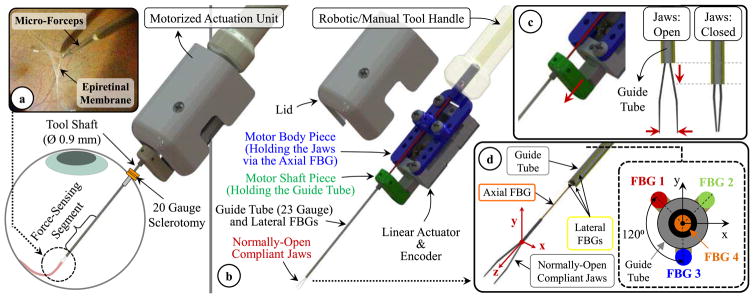
The design of our micro-forceps involves (1) an actuation mechanism to open/close the forceps jaws for firmly grasping thin membranous layers and (2) 4 strategically embedded FBG sensors to measure forces about the x, y and z axes of the tool separately. The assigned coordinate system of the forceps is shown in Fig. 1. The x and y axes form the transverse plane while the z-axis lies along the tool axis. During the grasping action, the jaws elastically deform to move toward each other along the x-axis. After grasping the membrane edge, the tool is moved mostly along its z-axis and x-axis to respectively pull and peel the membrane away from the adherent inner retina surface.
Fig. 1.
(a) Epiretinal membrane peeling using our motorized force-sensing micro-forceps with the force-sensitive region of the tool inserted into the eye through a 20 Gauge sclerotomy. (b) Components of the design (c) Motorized actuation mechanism driving the guide tube up/down for opening/closing the jaws. (c) The tool coordinate frame and FBG sensor configuration. The axial FBG sensor (FBG 4) at the center inside the guide tube and three lateral FBG sensors integrated on the guide tube (FBGs 1–3) measure axial (Fz) and transverse forces (Fx and Fy) at the tool tip, respectively.
A. Motorized Actuation Mechanism
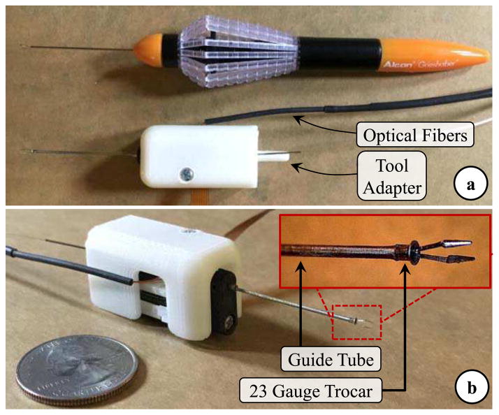
In vitreoretinal surgery, membrane peeling is often performed either by using a hook or a micro-forceps. Due to the inherent grasping capability, the latter is usually considered safer and preferred by surgeons. It enables easier and more controlled removal of the membrane from the eye with less slippage of the tissue and reduced number of grasping attempts close to the retina surface [53]. Currently a standard tool for this procedure is the disposable micro-forceps by Alcon Inc. (Fort Worth, TX), shown in Fig. 2a. It operates based on a squeezing mechanism [46]. When the tool handle is compressed, the tubular tool shaft is pushed forward, and squeezes the flexible jaws anchored to the back of the tool handle. When the tool handle is released the spring loaded mechanism pulls the tubular tool shaft back opening the jaws. Due to the moving parts within the mechanism during this actuation, studies have shown significant motion artifact at the tool tip [57], which limits tool tip positioning accuracy while trying to catch the membrane edge to begin delamination. Furthermore, such mechanical coupling between the tool handle and tip for actuation challenges the integration of the tool with many of the available systems for robot-assisted surgery as it can easily interfere with the operation of the attached robotic system. To address these issues, the design goal in our work has been devising a compact, lightweight and modular unit that can be controlled independently and remotely when necessary regardless of its site of attachment (such as a manual tool handle, a handheld micromanipulator [24–28,40] or a teleoperated/cooperatively-controlled robot [19–23,29]), resulting in the motorized micro-forceps shown in Fig. 1b.
Fig. 2.
(a) The standard 23 Gauge disposable micro-forceps by Alcon Inc. vs. the manufactured prototype of our motorized force-sensing micro-forceps. (b) Close-up view of the distal force-sensing segment. A fine-polished filleted stainless steel piece (23 Gauge trocar) was bonded at the distal end of guide tube, to modify the jaw/guide tube interface so that the reaction force during tool actuation is consistently smaller and its adverse influence on axial FBG sensor is minimal.
The actuation of our micro-forceps is provided by a compact (28 × 13.2 × 7.5 mm) and lightweight (4.5 g) piezoelectric linear motor (M3-L, New Scale Technologies Inc., Victor, NY) with its embedded driver and encoder providing precise position control. The normally-open compliant jaws are taken out from a standard disposable 23 Gauge micro-forceps (Alcon Inc., Fort Worth, TX). They are passed through a 23 Gauge stainless steel guide tube and firmly anchored to the motor body. The guide tube is attached to the shaft of the linear motor, so that when the motor is actuated, it drives the guide tube up and down along the z-axis, releasing or squeezing (thus opening or closing) the forceps jaws (Fig. 1c). The parts connecting the guide tube to the motor shaft, housing the motor, anchoring the jaws to the motor body and the lid shielding the mechanism were built using 3D printed Acrylonitrile Butadiene Styrene (ABS). The assembled actuation (Fig. 2b) unit occupies a space of 1.8 × 1.8 × 3.5 mm and weighs approximately 8.9 grams, which is close to the weight of Alcon’s 23 Gauge disposable micro-forceps (about 7.9 grams).
B. FBG Sensor Configuration
The exerted forces in membrane peeling are typically along the x-axis of the instrument during delamination and mostly tensile in z-axis while pulling the membrane away from the retina. Experiments in porcine cadaver eyes have shown forces mostly less than 7.5 mN [16]. Measuring these very fine forces without adverse contribution from the sclerotomy requires locating the sensor inside the eye, hence a sensor that (1) can fit through a small incision (Ø≤0.9 mm) on the sclera, (2) is sterilizable and biocompatible, and (3) can provide sub-mN accuracy for transverse force measurements and predict the axial load within an accuracy less than 2 mN. Based upon these constraints, our design employs 4 FBG sensors which all have one 3 mm FBG segment with center wavelength of 1545 nm (Technica S.A., Beijing, China).
Following a similar strategy to our previous 2-DOF force-sensing tools [44–48], we fixed 3 lateral FBGs (Ø=80 μm) evenly around the 23 Gauge guide tube using medical epoxy adhesive (Loctite 4013, Henkel, CT) to capture the transverse forces (Fx and Fy) at the tool tip (Fig. 1d). New in this work is the fourth FBG sensor (Ø=125 μm) added to detect the tensile forces along the tool axis that arise when the membrane is pulled away from the retina. The location of this sensor is critical to maximize axial force sensing accuracy. Our previously developed 3-DOF force-sensing hook tool [50] employed a customized flexure with an axial FBG located in the tool center. Based on this experience, our initial micro-forceps concept hypothesized that centrally locating the axial FBG sensor inside the guide tube at the distal end of jaws (Fig. 1d) could provide the best decoupling between transverse and axial forces. In this configuration, the sensor lies along the neutral axis for transverse loads. When there are axial pulling forces, the central FBG sensor goes under tension, ideally inducing a linearly increasing Bragg wavelength. Nevertheless, different than the hook tool, this is an actuated tool. As the micro-forceps is opened/closed, varying reaction forces are generated at the interface between the forceps jaws and the guide tube. Our preliminary experiments (applying axial loads varying within 0–25 mN at the tool tip using the setup which will be described in detail under Section IV.A) showed that the frictional and elastic deformation forces generated during tool actuation may significantly degrade the response of the sensor and may hinder the measurement of axial force at the tool tip. As a remedy, we studied an alternative concept, where the forceps jaws are modified by flattening one arm and bonding the axial FBG sensor on the flat arm so that its sensitive region is located out of the guide tube close to the tip [54]. Although this architecture ensured that the axial sensor response is not affected from tool actuation, the asymmetric design complicated the calibration procedure as well as the force decoupling and computation steps. In this work, instead of customizing the jaws, we maintained the axial FBG in the tool center inside the guide tube preserving the axial symmetry of the tool and modified the jaw/guide tube interface by attaching a fine-polished and filleted piece, the introduction section of a standard 23 Gauge trocar with the cannula section trimmed off [63] at the distal end of the guide tube as shown in Fig. 2b. The inner diameter of the trocar fit onto the guide tube, and the flange member at its proximal end was trimmed to fit through a 20 Gauge opening (Ø=0.9 mm). Using medical epoxy adhesive (Loctite 4013, Henkel, CT), it was bonded onto the guide tube such that the flange member of the trocar is at the distal end of the tool and the filleted end of the trocar’s hollow bore contacts the jaws for squeezing and closing them. This modification aimed at lowering the frictional forces during the actuation of the tool, preventing the jaws from getting stuck, enabling the applied axial forces to generate sensible strain on the axial FBG with the same sensitivity regardless of the opening state of the jaws. This functionality will be verified through finite element simulations in the next section, and the effect of actuation on the axial FBG response will be experimentally characterized in Section IV.B.
C. Finite Element Analyses
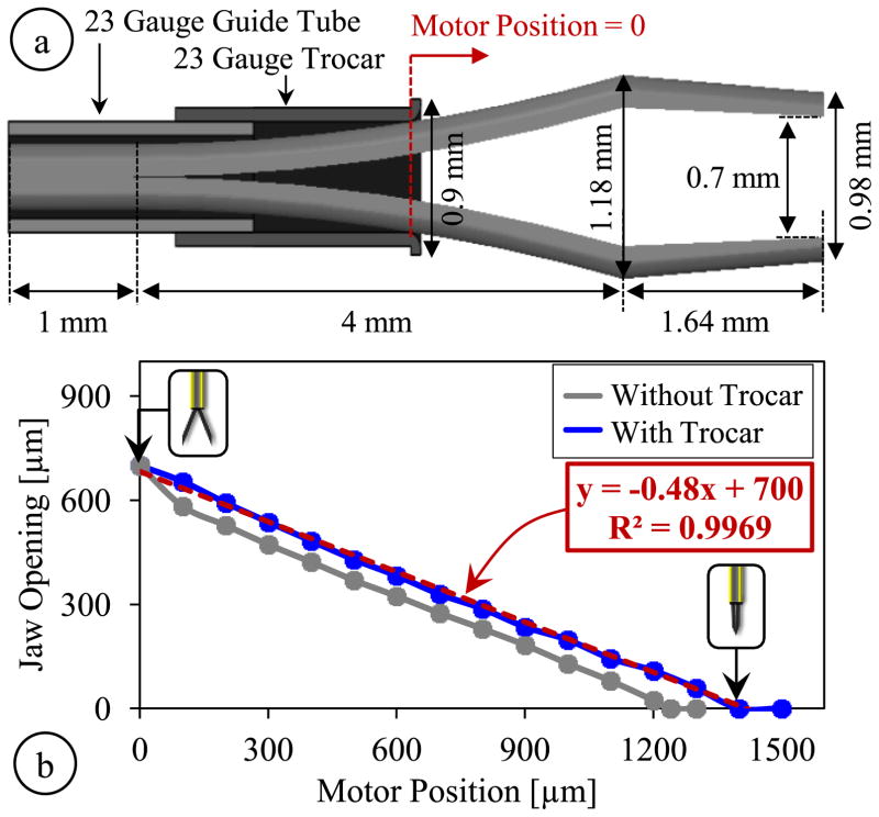
The motorized and encoded actuation provides a highly repeatable response, which enables a consistent correlation between the motor position and the opening between the jaws. In order to identify the kinematics of our tool, we first found the geometric parameters of the jaws taken out from Alcon’s disposable 23 Gauge micro-forceps. We used a digital microscope to capture projection images of the jaws, and then used Digimizer (MedCalc Software, Belgium) software to process these images. Resulting geometric parameters are shown in Fig. 3a. Next, we implemented the identified jaw model and the 23 Gauge guide tube in ABAQUS 6.13 (Dassault Systems, USA) software to simulate the opening/closing action of jaws both with and without the trocar at the distal end of the guide tube. The material of jaws and the guide tube were both set as stainless steel, SS316 (Young’s modulus=193 GPa and Poisson ratio=0.3). The jaws were maintained fixed while an increasing displacement was applied to the proximal end of the guide tube to gradually close the jaws, generating the plots shown in Fig. 3b. According to simulation results, when the jaws are fully open, the forcep tips are about 0.7 mm apart. As the guide tube is driven forward, the jaw opening decays nonlinearly at a decreasing rate without the trocar attachment. When the trocar is used, the jaws close with an almost linear response, at a rate of about 0.48 μm/μm. For full closure, using the trocar requires slightly larger translation of the guide tube, approximately 1400 μm in comparison to the 1240 μm without the trocar; however, this is still within the travel range of the linear actuator (6 mm) and does not correspond to a significant difference in the time it takes to fully close the jaws thanks to the fast response of the actuator (>5mm/s).
Fig. 3.
(a) Geometric parameters of the jaw model, guide tube and the trocar attachment used in finite element simulations, (b) The micro-forceps kinematics with and without the trocar attachment. While fully open, the jaw tips are 0.7 mm apart; full closure requires driving the motor about 1240 μm without the trocar and 1400 μm with the trocar. An almost linear response is obtained with the trocar.
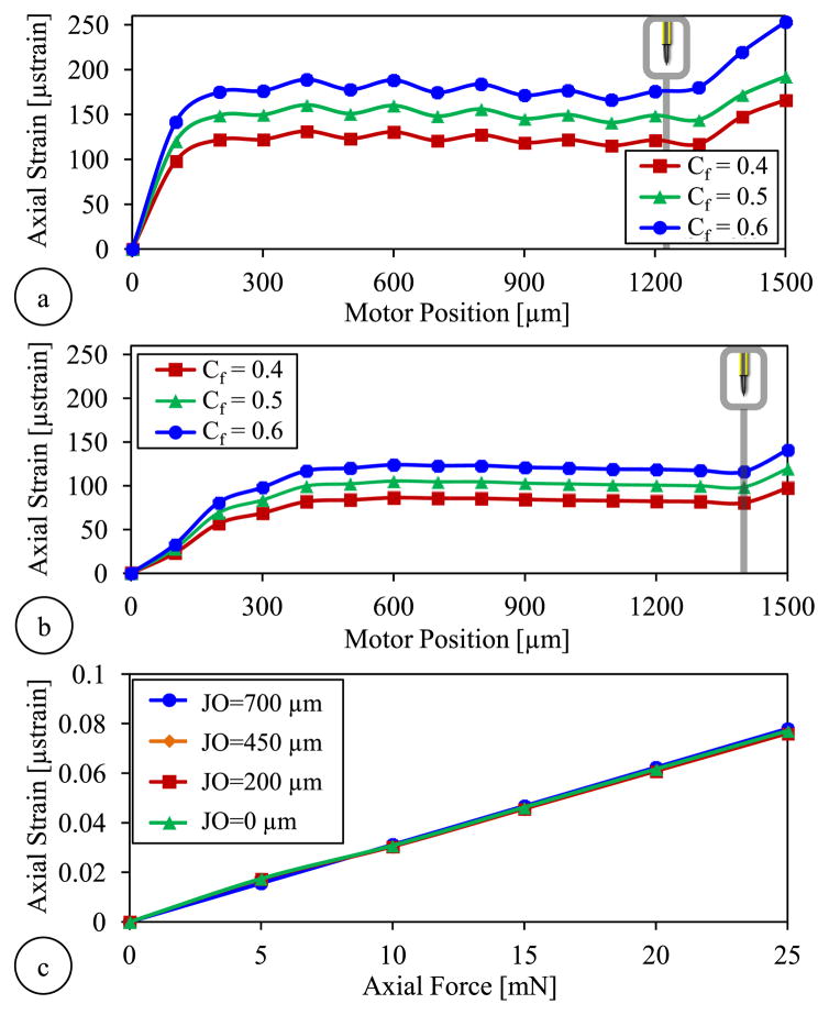
Next, we simulated the variation of the strain induced on the axial FBG during the actuation of the forceps. Since the exact value of the friction coefficient at the jaw/guide tube interface is not known, we analyzed the behavior for three different coefficients (Cf =0.4, 0.5 and 0.6) considering typical steel-steel dry contact properties. Results in Fig. 4a show that using the bare guide tube, the strain rises very rapidly initially at a decreasing rate during the first 300 μm of motor actuation. The trocar attachment leads to a more gradual increase in strain. After the jaws are fully closed (motor position reaches 1240 μm without the trocar and 1400 μm with the trocar), driving the motor forward further does not change the jaw opening but squeezes the jaws more, producing higher grasping force, and leading to a rapid rise in strain in all cases. Higher friction coefficients generate greater strain during actuation regardless of the trocar. However, for each value of friction coefficient, the use of trocar clearly lowers the strain level. For instance, for Cf = 0.5, without the trocar, full closure of the forceps generates of about 140 μ strains as compared to 98.5 μ strains with the trocar. The actual effect in the Bragg wavelength of the axial sensor will be characterized experimentally in Section IV.B.
Fig. 4.
Finite element simulation results showing the axial FBG response to tool actuation for various levels of friction coefficient (Cf) at the jaw/guide tube interface (a) without the trocar and (b) with the trocar attachment at the guide tube’s tip. Larger friction coefficients produce more strain. Lower strain levels are observed with the trocar. (c) The force-induced strain on the axial FBG vs. the applied axial load when the trocar attachment is used: the strain is linearly correlated with the axial load, and the sensitivity is almost identical for all levels of jaw opening (JO).
In order to monitor the influence of axial forces at the tool tip, we ran additional simulations for the configuration with the trocar attachment. We applied forces at the tip of jaws along the z-axis for various levels of jaw opening. Simulations involved forces ranging from 0 to 25 mN in increments of 5 mN. For each load condition, the motor was moved from 0 (fully open state) to 1400 μm (fully closed state), and the strain on the axial FBG sensor was recorded at each 100 μm step. After subtracting the previously identified actuation-induced strain component for each motor position (Fig. 4a), we computed and plotted the strain purely due to the applied axial load for each jaw opening. Results in Fig. 4c show that with the modified jaw/guide tube interface, the variation of force-induced strain on the axial FBG is linear for all jaw states (from fully closed to fully open); and the slope of the response remains almost the same regardless of the opening between the forceps jaws.
III. Force Computation Algorithm
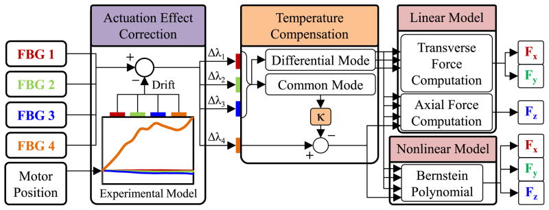
In order to transform the optical wavelength information from each embedded sensor to axial and transverse force values, we use the force computation algorithm summarized in Fig. 5. As discussed in Section II, the FBG sensors in our design are bonded to parts that move during the actuation of the forceps, i.e. opening/closing the jaws induces undesired drift in sensor readings. Since the actuation is performed by a precision motor with an integrated encoder, the deformation and resulting reaction forces during actuation are highly repeatable, and the influence on each FBG sensor can be modeled as a function of the motor position [56]. This model accounts for the frictional and elastic deformation forces at the jaw/guide tube interface inducing strain especially on the axial FBG. The effect of actuation on lateral FBGs are presumably minor since the lateral FBGs are mostly sensitive to the transverse deformations, which ideally do not take place assuming perfectly aligned parts and purely linear translation of the guide tube. Furthermore, apart from the material and dimensions of the forceps structure, the model may vary depending upon the medium in which the forceps is being operated (air, water, etc) as the coefficient of friction at the jaw/guide tube interface may change. We will verify these assumptions and identify the actuation influence through experiments in Section IV.B.
Fig. 5.
Force computation algorithm using an experimentally identified model to cancel the actuation-induced drift in FBG sensor readings based on the motor position and two distinct (linear and nonlinear) methods for transforming the corrected sensor readings into transverse (Fx and Fy) and axial (Fz) force information.
During the actual use of the micro-forceps, based on the identified actuation model and sensed motor position, the readings from each FBG sensor are corrected, simply by subtracting the estimated Bragg wavelength shift due to actuation. Although the temperature in patients’ eyeballs is fairly constant, FBG sensors are typically very sensitive to temperature changes (approximately 10 pm/° C). Hence, force sensing robustness against small thermal fluctuations is a desired feature. After the actuation effect correction, we cancel out the drift due to thermal changes based on the common mode of lateral FBGs, which tool tip forces from will be further detailed in the remainder of this section. To compute the corrected and temperature compensated sensor readings, we explore the use of two distinct methods: (1) a linear method based on ideal decoupling of transverse and axial forces, (2) a nonlinear regression based on Bernstein polynomials.
A. Linear Method
1) Transverse Force Computation
Assuming small elastic deformations, the guide tube can be modeled as an Euler-Bernoulli beam under transverse (Fx and Fy) and axial (Fz) loading at the tool tip, inducing a linearly proportional local elastic strain on each lateral FBG and thus a linearly proportional shift in the Bragg wavelength of each sensor. In addition, even slight variations in ambient temperature (ΔT) may cause a drift in the Bragg wavelength. Then, the combined Bragg wavelength shift (Δλi) for each lateral FBG sensor (FBGs 1, 2 and 3) can be expressed as
| (1) |
where and are constants associated with the x, y, z forces and the temperature change, respectively. Since the lateral FBGs are closely located within the same ambient, ideally, they are equally affected from the axial load ( ) and the temperature variation ( ). When the mean Bragg wavelength shift in all three lateral sensors is computed, due to axisymmetric distribution of lateral FBGs around the guide tube (120° apart from each other as shown in Fig. 1d), the terms related to the transverse forces cancel each other as detailed in [44], resulting in the common mode (Δλmean) which is a function of the axial force and the temperature change only.
| (2) |
The effect of temperature change and axial force in sensor readings can be eliminated by subtracting the common mode from Bragg wavelength shift of each sensor.
| (3) |
The remaining differential mode of each sensor ( ) can then be used in the following equation to compute the transverse forces:
| (4) |
where Ctr is a 2×3 coefficient matrix which represents the linear mapping from optical sensor readings to the force domain, and will be found via a calibration procedure in Section IV.D.
2) Axial Force Computation
In our design, the axial FBG (FBG 4) lies along the tool axis ideally centered inside the guide tube, which would result in an ideal decoupling of transverse and axial loads, i.e. an axial FBG response immune to Fx and Fy, sensing purely Fz. However, due to the very small dimensions and imperfections resulting from tool assembly, this condition is very hard to achieve. Even if the axial FBG is slightly off-centered, besides the elastic strain due to Fz, the axial FBG will experience a bending moment due to Fx and Fy. In addition, excessive off-centered loading at the tool tip may also induce torsion on the axial fiber and deteriorate the FBG response, which we assume will be negligible considering the targeted force range (0–25 mN) and the small tool diameter (0.9 mm). Furthermore, changes in ambient temperature will induce a drift in the measured Bragg wavelength. Assuming all aforementioned sources of strain contribute linearly to the axial sensor reading, the total wavelength shift observed in FBG can be formulated as
| (5) |
where and are constants associated with Fx, Fy, Fz and temperature change, respectively. Since the axial and lateral FBGs share the same environment, we hypothesize that the thermal drift of the axial FBG and that of the common mode of the three lateral FBGs are linearly correlated ( ), which will be experimentally verified in Section IV.D.
| (6) |
Based upon this hypothesis, by multiplying the common mode of lateral FBGs with a proper coefficient (κ) and subtracting it from Δλ4, the effect of temperature change can be eliminated.
| (7) |
Using the linear relationship previously found for the transverse forces and rearranging the terms, the axial force can be expressed as a linear combination of each sensor’s differential mode
| (8) |
where Cax is a 1×4 coefficient vector which will be identified via a calibration procedure in Section IV.D.
B. Nonlinear Method
Due to the very small dimensions and imperfections in tool fabrication, it may not be possible to accurately decouple the effect of axial and lateral loads using a linear model, especially on the axial FBG. We hypothesize that such a linear fitting may perform well only locally, when the transverse forces are much smaller than the axial load, which is hard to guarantee in epiretinal membrane peeling procedure. In order to obtain a global estimate of force, a nonlinear fitting method based on Bernstein polynomials, as demonstrated earlier for a 3-DOF force-sensing pick tool [50], can be used:
| (9) |
where cjklm denotes constant coefficients and denotes the differential mode (thermal drift eliminated response as described by equations (3) and (7)) of each FBG scaled down to [0,1] interval – since Bernstein polynomials exhibit good numerical stability within this range [51] – using the following equation:
| (10) |
terms in equation (10) are the Bernstein basis polynomials of order n defined as follows:
| (11) |
In our approach, in order to avoid overfitting with a reasonable sample size, we use a 2nd order regression by setting n=2 and defining
| (12) |
Then, equation (9) can be rearranged as
| (13) |
where B is a 1×81 row vector formed by the product of Bernstein basis polynomials and CBernstein is a 81×3 constant matrix. The coefficients in CBernstein can be found by applying known forces (Fx, Fy and Fz) in various directions at the tool tip, acquiring FBG wavelength data and forming a B vector for each recorded sample, and finding the best fit in the least squares sense.
IV. Experiments and Results
A. Setup
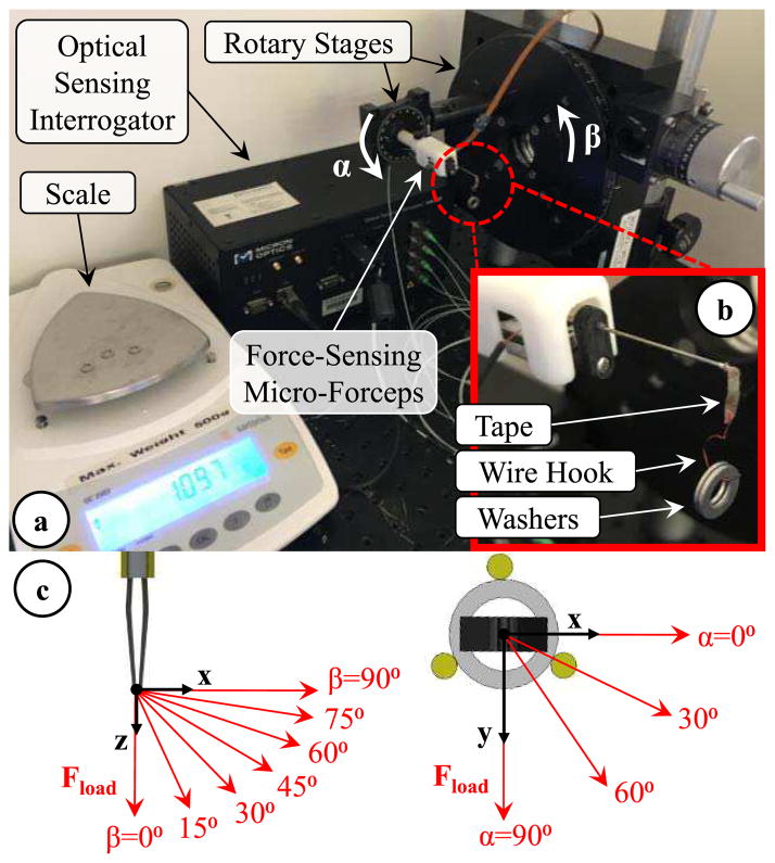
Using the setup shown in Fig. 6, we performed a series of experiments to model the effect of forceps actuation on force sensor readings, examine the repeatability of sensor outputs, identify calibration constants and validate the force computation methods presented in Section III. In order to acquire the Bragg wavelength of each FBG sensor, the setup employed an optical sensing interrogator (sm130–700 from Micron Optics Inc., Atlanta, GA). The force-sensing micro-forceps was mounted on a rotary stage to adjust the axial orientation (roll angle, α) of the tool. The stage was attached onto a second rotary stage to modify the pitch angle (β) and tilt the tool in the vertical plane. The jaws of the forceps were closed to grasp a thin (~80 μm thick) layer of tape carrying a wire hook. The wire hook was used to hang aluminum washers and apply varying forces at the tool tip (Fig. 6b). The washers were weighed by using a precision scale (Sartorius GC2502, Germany) which has a resolution of 1 mg and a repeatability of ±2 mg. The maximum test load was 23.35 mN, and each washer weighed about 4.67 mN. By changing the tool orientation (α and β) and the load hanging at the tip (Fload), various combinations of Fx Fy and Fz were generated as shown in Fig 5c. The resulting forces at the tool tip can be resolved into their x, y and z components using the following formulae:
| (14) |
| (15) |
| (16) |
Fig. 6.
Experimental setup. (a) The 3-DOF force-sensing micro-forceps was mounted on two rotary stages to control the roll (α) and pitch (β) angles of the tool. (b) By hanging washers onto the grasped hook, the magnitude of the applied force was changed. (c) Modulating the tool orientation (α and β), thus the direction of the applied force, various combinations of Fx, Fy and Fz were applied at the tool tip.
B. Effect of Actuation
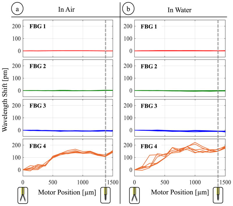
The goal of this experiment was to generate a model for compensating the detrimental effect of grasping motion on the FBG sensors. For this, the linear motor of the micro-forceps was actuated back and forth in discrete steps of 100 μm, and gradually opening/closing the forceps jaws. The jaws were fully closed after the motor was driven about 1400 μm forward from the fully open state, which is consistent with the simulation results previously presented in Fig. 3b. After each 100 μm step, the motor was stopped and the wavelength shifts of the FBG sensors were recorded. The open/close cycle was repeated 3 times, leading to 6 measurements for each sensor at each motor position. Following the identical procedure, the experiment was repeated whilst the tool tip was immersed in water.
Results in Fig. 7 show that the motorized actuation does not induce a detectable change in the output of lateral sensors (FBGs 1, 2 and 3). However, the Bragg wavelength of the axial sensor (FBG 4) significantly varies depending on the motor position and therefore the opening state of forceps jaws in air and water. The wavelength shift profiles closely follow the axial strain variation trend that was predicted through simulations in Fig. 4b. While operating in air, wavelength shifts up to 167 pm are recorded. These recordings show much better consistency among the 6 measurements taken per each motor position in comparison to our earlier prototype without the trocar attachment [56]. When the test is repeated in water, slightly larger shifts up to 222 pm are observed in the axial FBG output, and the consistency of readings at each motor position is relatively deteriorated. The small change can be attributed to the floating impurities inside water which can get stuck between the jaws and guide tube, and lead to larger reaction forces during actuation. Hence, the model relating wavelength shift to motor encoder readings is dependent also on the properties of the surrounding medium and needs to be experimentally tuned before each operation by opening/closing the forceps several times.
Fig. 7.
The effect of opening/closing the forceps on the lateral (FBG 1,2,3) and axial (FBG 4) sensors while operating (a) in air and (b) in water. The actuation induces high levels of wavelength shift on the axial sensor (up to 167 pm in air and up to 222 pm in water), which exhibit a consistent variation among repeated trials, and hence can be modeled as a function of motor position for each environment.
C. Repeatability
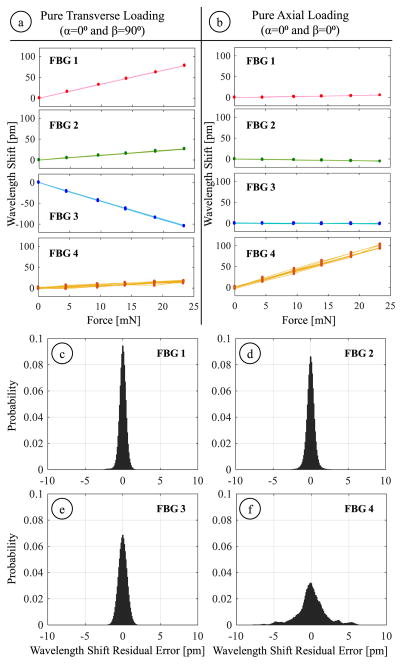
This experiment explored the consistency of the FBG sensor readings in response to axial and transverse loads. Forces were applied at the tool tip in 28 different directions by orienting the tool at 4 roll (α) and 7 pitch (β) angles. The roll angle ranged from 0° to 90° with 30° increments while the pitch angle was altered from 0° to 90° in steps of 15°. The magnitude of applied forces varied evenly at 6 levels within 0–23.35 mN. For each direction, the forcing was gradually increased up to 23.35 mN and then decremented back to zero by unloading the washers at the tool tip. The wavelength information from all four FBGs was acquired after the oscillations due to loading/unloading were fully damped out. This cycle was repeated 3 times, generating 6 measurements for each load case. For each measurement, 500 samples were recorded. As an example, Fig. 8a and 8b show the recorded sensor response for purely transverse and axial loading conditions.
Fig. 8.
Response of (FBG 1,2,3) and axial (FBG 4) sensors during two sample loading conditions: (a) pure transverse loading and (b) pure axial loading. Probability distribution of Bragg wavelength shift errors for lateral (c–e) and axial (f) FBG sensors under 168 different combinations of transverse and axial forces. The standard deviations are less than 0.6 pm for the lateral FBGs and is about 1.96 pm for the axial FBG, indicating a highly repeatable response.
The log data involved a total of 168 distinct loading conditions, 1008 measurements and 504,000 samples. To examine the repeatability of each sensor’s response, the recorded samples were grouped into 168 subsets so that each subset contained 3000 samples associated with the same loading condition. Within each subset, after identifying the mean Bragg wavelength shift for each FBG sensor, the deviations from the mean value (residuals) were computed. The residuals of all subsets were then combined to obtain the standard deviation for each FBG sensor as a measure of repeatability.
Figs. 8c–e show the probability distribution of the residuals for each FBG sensor. The standard deviations for the lateral FBG sensors (FBG 1, 2 and 3) are 0.47, 0.58 and 0.59 pm, respectively. The axial FBG sensor (FBG 4) exhibits slightly a more variable response with a standard deviation of 1.96 pm. Our optical sensing interrogator has a wavelength repeatability of 1 pm; its wavelength stability is 2 pm typically and 5 pm at maximum. Considering these values, we can conclude that the FBG sensors on our tool provide reliable repeatability that is consistent with the intrinsic properties of our optical sensing interrogator.
D. Calibration
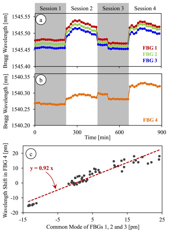
In order to identify the coefficients used in our force computation algorithm, we performed a set of calibration experiments. The goal in our first calibration experiment was to test the hypothesis of linear correlation between the temperature drift in common mode of lateral FBGs and the axial FBG. We recorded the Bragg wavelength variation in each FBG sensor while the tool was exposed to routine changes in room temperature, which involved gradual changes within ±2.5° C. In order to avoid disturbances due to air flow in the room, the setup was maintained inside a plastic box while acquiring data. The test was completed in 4 sessions; each session spanned a 225 minute period during which a measurement was taken in every 15 minutes. In between the sessions, we altered the roll and pitch angles to capture the effect of tool orientation on the thermal drift coefficient, if any.
The results are shown in Fig. 9, which display the changes in Bragg wavelength of each sensor due to 2 main sources. The larger jumps while moving to the next set of measurements are due to the modified tool orientation, thus the new loading at the tool tip. The rest of the variations within each session are purely due to thermal effects. We observe from Fig. 9a that the lateral FBGs exhibit almost identical sensitivity to thermal changes, whereas the drift in the axial FBG was slightly smaller (Fig. 9b). For a quantitative comparison of thermal effects, we evaluated the wavelength shift of all four sensors within each session, and computed the common mode of lateral FBGs. The wavelength shift in the axial FBG and the common mode of the lateral FBG sensors revealed a linear correlation with a covariance of 0.94, which verified that our assumption in Section III.A was approximately correct. The corresponding proportionality constant was found to be κ = 0.92 (Fig. 9c).
Fig. 9.
Thermal drift in lateral (a) and axial (b) FBG sensor readings during 4 test sessions each spanning a period of 225 minutes. (c) The Bragg wavelength shift in the axial FBG sensor shows a linear correlation with the common mode (average Bragg wavelength shift) of lateral FBG sensors with a proportionality constant of κ = 0.92.
Our second calibration experiment was aimed at monitoring the FBG response under various combinations of transverse and axial forces. In order to collect sufficient data with a fine enough sampling grid, we took the measurements recorded in Section IV.C (504,000 samples of log data with 6 levels of forcing in 28 different directions) and performed 4 additional analyses: global linear calibration, local linear calibration, global nonlinear calibration, and local nonlinear calibration.
1) Global Linear Calibration
After computing the differential mode of each sensor, the linear system of equations described in Section IV.A was formed and solved by using the method of least squares. The resulting coefficient matrix for the transverse forces in equation (4) was
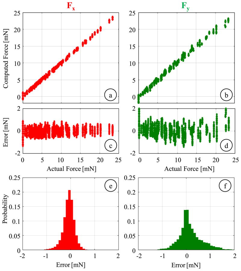
Considering the wavelength resolution of the optical sensing interrogator (1 pm) and the identified coefficient matrix, the linear method produces a transverse force resolution of about 0.14 mN, which is within the initial design target of 0.25 mN. The linear fitting results are shown in Fig. 10a and 10b for Fx and Fy, respectively. The estimated Fx values closely follow the actual forces with a root mean square (rms) error of 0.25 mN and a mean absolute error of 0.18 mN. A similarly accurate estimation is observed for Fy up to about 10 mN. However, beyond this level, slight deviations from the actual value are observed, leading to an overall rms error of 0.52 mN and a mean absolute error of 0.36 mN. The sliding contact between the jaws and the guide tube provides firm support along the x-axis of the tool, but not along the y-axis as shown in Fig. 6c. Therefore, large Fy forces can deform and dislocate the jaws inside the guide tube, which may change the overall geometry and deteriorate the linearity of the force sensor response. Nevertheless, this is not a major concern in membrane peeling since most of the applied forces lie along x-axis (peeling direction) due to the alignment of jaws, and excessive side loads (Fy) are highly unexpected. The histograms of the residual errors (Fig. 10e and 10f) show that the probability of errors beyond 1 mN is very low for both Fx and Fy, which have standard deviations of 0.27 mN and 0.49 mN respectively indicating a good repeatability.
Fig. 10.
Global linear calibration results for transverse forces: (a,b) Calculated Fx and Fy versus the actual values. (c,d) residual errors versus the actual forces, (e,f) probability distribution of residuals (bin size = 0.1 mN). The global linear fitting can predict the applied forces with an rms error of 0.25 mN and 0.52 mN for Fx and Fy, respectively.
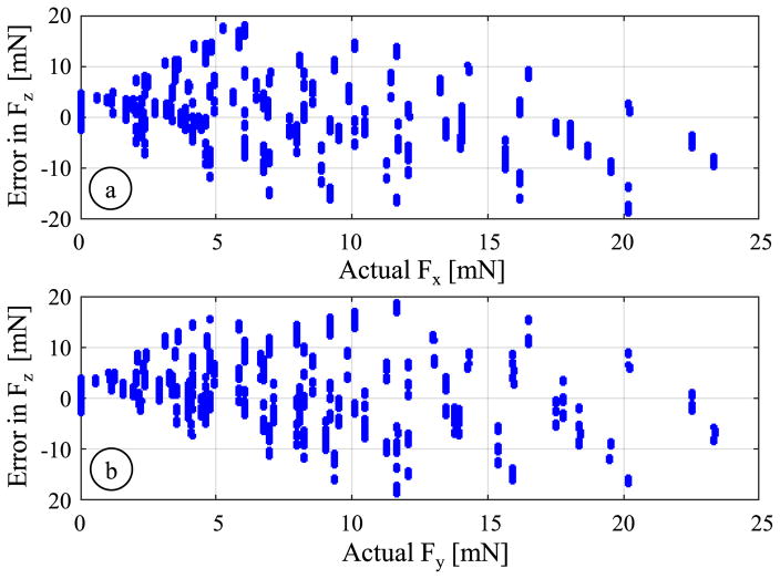
Solving the system of equations given by (8), we were not able to identify an adequately accurate fitting to estimate the axial load. The resulting coefficient Cax led to very large errors (an rms error of 8.34 mN, a mean absolute error of 6.19 mN, and a standard deviation of 3.87 mN) especially in the presence of significant transverse loads in addition to axial forces. Fig. 11 shows that the magnitude of errors in axial force computation steeply rises with greater magnitude of transverse forces (both Fx and Fy), which suggests that the assumption of modeling the axial FBG response as a linear combination of axial and transverse load effects does not hold globally, as discussed in Section III.
Fig. 11.
Axial force (Fz) computation error versus the concurrent transverse load along (a) x-axis and (b) y-axis based on the global linear calibration. The magnitude of errors rapidly grows when larger transverse forces are applied, deteriorating the linearity of the axial FBG.
2) Local Linear Calibration
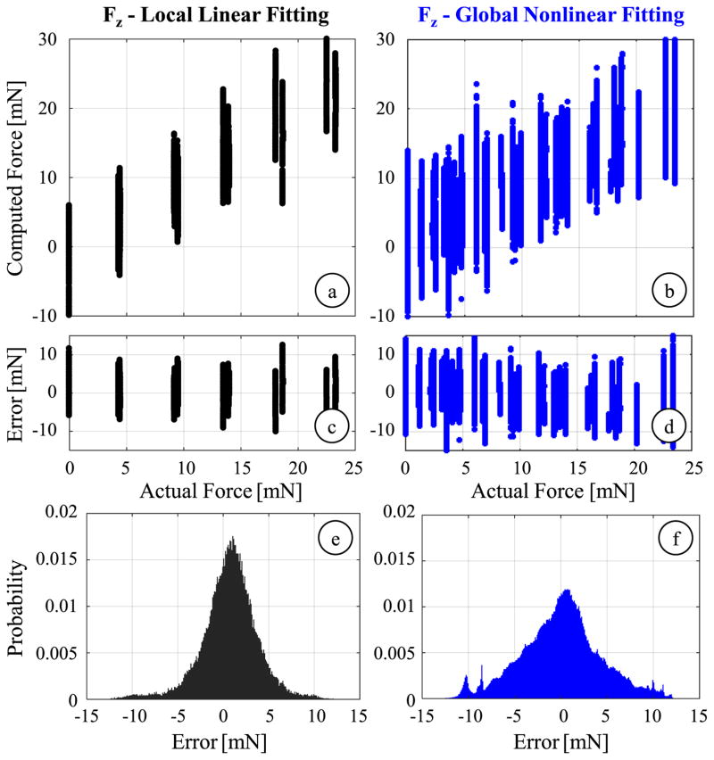
In membrane peeling, forces applied in the transverse plane are mostly along the peeling direction, which corresponds to the x-axis of our tool. Our previous membrane peeling experiments on various types of artificial phantom also support that transverse loads containing large Fy (associated with α > 30) are not very likely in practical use of the micro-forceps [52]. In an attempt to find a more accurate linear fitting for the axial force, we first analyzed a subset of the calibration data associated with α ≤ 30°. However, limiting α and hence Fy alone did not lead to any significant improvement in axial force sensing accuracy. The rms error in estimated Fz was still 7.08 mN and the mean absolute error was 5.41 mN. Next, we considered a smaller subset limiting both the pitch β ≤ 15°) and roll α ≤ 30°) angles so that both of the transverse force components were constrained (Fx < 6.04 mN and Fy < 3.02 mN), and the applied forces were dominantly axial. For this subset of 72,000 samples, it was possible to obtai
which indicates an axial force resolution of about 1.32 mN. Fig. 12a illustrates the resulting fit, and the distribution of residuals is shown in Figs. 12c and 12e. Accordingly, the errors are reduced to an rms value of 3.17 mN and a mean absolute value of 2.38 mN. The standard deviation is 3.09 mN, indicating slightly better repeatability. The improved accuracy with this reduced data set verifies our hypothesis on the loss of linearity in the presence of dominant transverse loads. Yet, this method is not feasible for estimating axial forces, not only because the resulting error is still over our accuracy target (2 mN), but also because in membrane peeling a significant portion of the exerted forces are transverse rather than axial, which remains in contrast to the extremely confined workspace of this method.
Fig. 12.
Axial force computation results for local linear calibration using samples with limited roll (α ≤ 30°) and pitch (β ≤ 15°) angles (black), and for global nonlinear calibration (blue): (a,b) The comparison of computed values to the actual force level, (c,d) variation of error with respect to the axial force magnitude, (e,f) probability distribution of residuals (bin size = 0.1 mN). The latter provides almost the same sensing accuracy as the local fitting, but for the entire range of force directions.
3) Global Nonlinear Calibration
Using the entire log data of 504,000 samples, we fit a nonlinear regression model based on 2nd order Bernstein polynomials to better estimate both the transverse and axial forces. The obtained coefficient vector CBernstein derives a resolution of 0.074 mN for Fx and Fy, and 1.85 mN for Fz, respectively. The accuracy in computing the transverse forces are slightly better than the linear method with an rms error of 0.15 mN for Fx and 0.25 mN for Fy. More importantly, the axial force estimation is significantly improved in comparison to the global linear fitting results. The residual error spans approximately ±4.33 mN while the mean absolute error is 3.34 mN. Although the results displayed in Fig. 12 are still unsatisfactory based upon our accuracy criterion (2 mN), they show an important improvement: the nonlinear regression provides a global axial sensing accuracy similar to what could be obtained by the linear fitting only locally.
4) Local Nonlinear Calibration
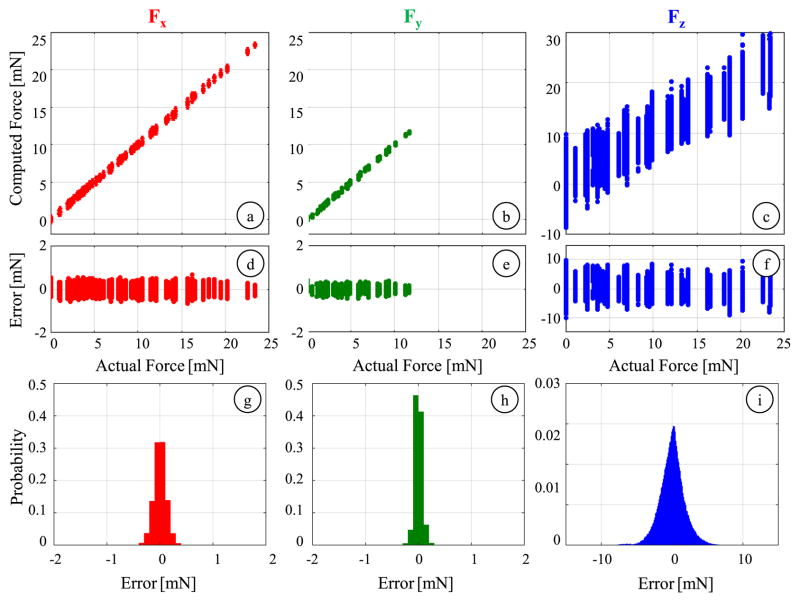
Considering that forces associated with large Fy forces are not very probable during an actual membrane peeling operation as discussed previously, we repeated our nonlinear calibration method using a reduced dataset (α ≤ 30°), without limiting Fx (0–23.35 mN) which is expectedly the dominant force component along the peeling direction but constraining Fy below 11.7 mN. This corresponds to a dataset of 252,000 samples with 84 distinct loading conditions. The regression analysis revealed a coefficient vector (CBernstein) providing a finer force resolution in comparison to all of the previous fittings: 0.01 mN for Fx and Fy and 0.38 mN for Fz. The resulting force estimates and associated errors are plotted in Fig. 13. The rms errors are 0.12, 0.07 and 1.76 mN for Fx, Fy and Fz, respectively, which are all sufficiently smaller than our initial design target (0.25 mN for transverse and 2 mN for axial forces). For the axial load, the magnitude of the residual error remains mostly within the ±5 mN envelope across the entire force range as shown in Fig. 13f. Fig. 13g–i illustrates the probability distributions of the residuals, which show that with the local nonlinear calibration errors mostly stay under 0.5 mN for Fx and Fy, and 5 mN for Fz. The standard deviations of errors are 0.12, 0.07 and 1.76 mN respectively, which show significantly better repeatability of readings in comparison to the aforementioned calibration methods.
Fig. 13.
Results of local nonlinear calibration using samples with limited roll (α ≤ 30°) angles for computing Fx (red), Fy (green) and Fz (blue): (a–c) The comparison of computed values to the actual force level, (d–f) variation of residuals with respect to the force magnitude, (g–i) probability distribution of residuals (bin size = 0.1 mN). By limiting the roll angle (α ≤ 30°), samples with excessive Fy (>11.7 mN), which are not very likely in an actual membrane peeling operation, were excluded from calibration. The rms errors in estimating Fx, Fy and Fz are 0.12, 0.07 and 1.76 mN respectively.
E. Validation
For validating the performance of our nonlinear force computation method, we took measurements at loading conditions that were not used during the calibration, still limiting the transverse loads to the range of interest in membrane peeling, i.e. α ≤ 30°. We investigated if the identified local calibration constants could still accurately predict the applied forces. The validation experiment consisted of forces ranging from 0 mN to 23.35 mN in increments of 4.67 mN while holding the tool at 2 different roll angles (α = 0°, 30°) and 3 different pitch angles (β = 20°,40°,70°). Each case was repeated 6 times and 500 samples were collected per case. The data set was further extended by adding 15 more measurements per each roll angle at randomized pitch angles (0°–90°) and forces (0–23.35 mN), producing a total of 66 distinct loading conditions and 123,000 samples.
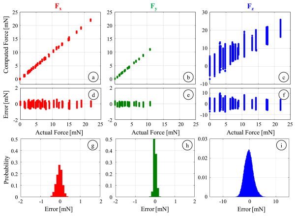
Using validation dataset, we observed a similar force computation performance to what was obtained with the calibration dataset (Fig. 14). Our locally fit nonlinear model is able to accurately predict the applied transverse forces within the considered force range, 0–25 mN for Fx and 0–11.7 mN for Fy. The rms errors are 0.16 mN and 0.07 mN for Fx and Fy, respectively. The axial forces are captured with an rms error of 1.68 mN, which is satisfactorily smaller than our design target of 2 mN. The standard deviation of errors indicate a force sensing repeatability of 0.15 mN, 0.07 mN and 1.67 mN about x, y and z axes, respectively. These results demonstrate that the 3-DOF force-sensing micro-forceps with the nonlinear force computation method can provide measurements within the desired sensitivity and accuracy.
Fig. 14.
Results of the validation experiment for computing Fx (red), Fy(green) and Fz (blue): (a–c) The comparison of computed values to the actual force level, (d–f) variation of residuals with respect to the force magnitude, (g–i) probability distribution of residuals (bin size = 0.1 mN). Tested data consists of loading conditions that were not involved during calibration. The identified local nonlinear regression can still accurately predict the applied forces with rms errors of 0.16, 0.07 and 1.68 mN for Fx, Fy and Fz, respectively.
V. Discussion
Our earlier works demonstrated that the temperature compensation method described in Section III provides robust transverse and axial force measurements against thermal changes for other tools [44, 50]. In this work, the first set of our calibration experiments explored the thermal influence on each FBG sensor output in response to slow and gradual ambient temperature variation, which revealed similar behavior to that observed in our previous 3-DOF force-sensing pick tool [50]. In case of sudden ambient temperature variations though, such as the instant when the tool is inserted into the eye, whether the linear correlation between the axial sensor response and the common mode of lateral sensors is valid remains controversial. In practice, this issue can be alleviated by rebiasing the force sensor to adapt to the new temperature level right after the tool is placed inside the eyeball. After this time, the expected thermal fluctuations inside the eye will be relatively small and gradual so that our thermal drift method cancelling based on common mode of lateral sensors can be used. There are several potential solutions that can improve the robustness of our force-sensing tool to thermal changes: adding a separate reference FBG [58], using two different wavelengths [59], or using different optical modes [60,61]. Our future work involves further exploration of these methods for faster and more accurate compensation of thermal drift in our 3-DOF force-sensing micro-forceps@perio
In order to compute forces from the optical sensor information, we explored the use of a nonlinear fitting based on second order Bernstein polynomials. Increasing the polynomial order may potentially improve the sensing accuracy, especially in the axial direction. However, identifying a higher order polynomial without overfitting requires calibration experiments that capture the FBG sensor outputs for a finer grid of forces. Such extensive dataset is quite challenging to acquire with the presented setup. Furthermore, the manual operation of rotary stages and loading/unloading of washers to modulate the loading induced at the tool tip is prone to human error. However, using a robotic calibration approach similar to [50], it is possible to collect more samples reliably in a shorter time and identify a more accurate higher order nonlinear force computation model.
In our calibration and validation experiments, the applied forces in the axial direction were always tensile. Therefore, the identified models do not describe the behavior for compressive loads. In addition, the final accuracy and resolution values were obtained for a limited force range of 0–25 mN with minor force component perpendicular to the peeling direction (Fy < 11.7 mN). Although, these may be interpreted as limitations of our approach, they are highly relevant to the actual clinical scenario. In epiretinal membrane peeling, to avoid retinal injuries, the magnitude of forces need to be maintained typically below 10 mN [64]. Also, the membrane is pulled away from the retina surface, which causes axial loads on the micro-forceps tip to be tensile if any. The exerted forces in the transverse plane follow the direction of tool motion, which means they are usually along the opening/closing direction of the jaws (x-axis of our tool). These practical facts support the constraints of our force computation model for epiretinal membrane peeling. Nevertheless, using the same experimental method, the instrument can be calibrated to the desired force domain for a different application as well@perio
Based on the practically relevant force ranges, using our nonlinear method showed that the rms error in axial force sensing could be lowered under 2 mN. This is a significant improvement on our previously reported results [54], and is presumably useful for limiting intra-operative forces and preventing retinal injuries in epiretinal membrane peeling. Nevertheless, for our other aims - including quantitative assessment of differing surgical techniques, objective evaluation of the surgical performance and accurate modeling of retinal tissues – our future work aims to further improve the axial sensing accuracy. Some potential methods include using higher order nonlinear models for force computation, and exploring customized sensor architectures that provide better decoupling between axial and transverse forces [62].
VI. Conclusion
In this study, we developed a novel force-sensing micro-forceps that can capture 3-DOF tool-tissue interaction forces during membrane peeling in vitreoretinal surgery. To the best of our knowledge, this is the first micro-forceps that can sense not only transverse but also the axial forces at the tool tip to be used in vitreoretinal surgery. Main contributions are the calibration procedure and force computation methodology using FBG sensor readings influenced by a mixture of sources, such as thermal changes and tool actuation apart from tool tip forces. In design, the sensitized segment of the instrument was located close to tool apex inside of the eye so that tool-tissue interaction forces at the tool tip could be detected without the influence of any other forces along the tool shaft. By strategically embedding 4 FBG sensors on the tool shaft, the decoupling between transverse and axial forces was maximized. The grasping functionality was provided via a compact motorized unit which enabled tool actuation without requiring any mechanically coupled handle mechanism in contrast to the existing standard micro-forceps and ensured a highly repeatable behavior in FBG sensor outputs during actuation. Through experiments inside air and water, we studied the actuation influence on sensor outputs as a function of motor position. The resulting model was later used to cancel out the undesired influence on the sensors due to tool actuation. We carried out experiments to test the repeatability of sensor outputs, calibrate the force sensor and validate its performance. For computation of forces, two distinct methods were explored: a linear regression and a nonlinear fitting based on second-order Bernstein polynomials. Results showed that the FBG sensors provide a highly repeatable output, and the nonlinear force computation approach provides superior accuracy. Based upon the developed calibration and force computation methods, our future studies aim at optimization of the tool structure and fabrication process to improve the force sensing accuracy.
This work modeled and evaluated the force response of our tool based upon static measurements, where samples were acquired after the response of each sensor reached steady-state. Similar to the strategy we followed for our earlier 2-DOF force-sensing tool [65], we will investigate the dynamic response of our new 3-DOF force-sensing instrument and evaluate its performance in estimating rapidly changing force profiles in future experiments. In addition, the micro-forceps was devised as a modular unit so that it can be easily combined with robotic systems. Our future work aims at integrating our tool with a robotic assistant by combining motion compensation and image-guidance features with various force feedback and force control methods to aid safe grasping and peeling of epiretinal membranes. Upon system integration, we aim to perform feasibility studies initially on artificial membrane peeling phantoms, then on biological membranes, and eventually using ex vivo and in vivo animal models.
Acknowledgments
Research supported in part by the National Institutes of Health under R01 EB000526, and in part by Johns Hopkins University internal funds as Research to Prevent Blindness, The J. Willard and Alice S. Marriott Foundation, The Gale Trust, Mr. Herb Ehlers and Mr. Bill Wilbur.
Contributor Information
Berk Gonenc, CISST ERC at Johns Hopkins University, Baltimore, MD 21218 USA.
Alireza Chamani, CISST ERC at Johns Hopkins University, Baltimore, MD 21218 USA.
James Handa, Wilmer Eye Institute at The Johns Hopkins School of Medicine, Baltimore, MD 21287 USA.
Peter Gehlbach, Wilmer Eye Institute at The Johns Hopkins School of Medicine, Baltimore, MD 21287 USA.
Russell H. Taylor, CISST ERC at Johns Hopkins University, Baltimore, MD 21218 USA.
Iulian Iordachita, CISST ERC at Johns Hopkins University, Baltimore, MD 21218 USA.
References
- 1.Kempen JH, O’Colmain BJ, Leske MC, Haffner SM, Klein R, Moss SE, Taylor HR, Hamman RF. The prevalence of diabetic retinopathy among adults in the United States. Arch Ophthalmol. 2004;122(4):552–563. doi: 10.1001/archopht.122.4.552. [DOI] [PubMed] [Google Scholar]
- 2.Zhang X, Saaddine JB, Chou CF, Cotch MF, Cheng YJ, Geiss LS, Gregg EW, Albright AL, Klein B, Klein R. Prevalence of diabetic retinopathy in the United States. JAMA. 2010;304(6):649–656. doi: 10.1001/jama.2010.1111. [DOI] [PMC free article] [PubMed] [Google Scholar]
- 3.Saaddine JB, Honeycutt AA, Narayan KV, Zhang X, Klein R, Boyle JP. Projection of diabetic retinopathy and other major eye diseases among people with diabetes mellitus. Arch Ophthalmol. 2008;126(12):1740–1747. doi: 10.1001/archopht.126.12.1740. [DOI] [PubMed] [Google Scholar]
- 4.Sharma SS, Mahmoud TH, Hariprasad SM. Surgical management of proliferative diabetic retinopathy. Ophthalmic Surg Lasers Imaging Retin. 2014;45(3):188–193. doi: 10.3928/23258160-20140505-01. [DOI] [PubMed] [Google Scholar]
- 5.Chang S, Gregory-Roberts EM, Park S, Laud K, Smith SD, Hoang QV. Double peeling during vitrectomy for macular pucker: the Charles L. Schepens Lecture. JAMA Ophthalmol. 2013;131(4):525–530. doi: 10.1001/jamaophthalmol.2013.2176. [DOI] [PubMed] [Google Scholar]
- 6.Ng CH, Cheung N, Wang JJ, Islam A, Klein EK, Klein R, Wong TY. Prevalence and risk factors for epiretinal membranes in a multi-ethnic United States population. Ophthalmology. 2011;118(4):694–699. doi: 10.1016/j.ophtha.2010.08.009. [DOI] [PMC free article] [PubMed] [Google Scholar]
- 7.Christensen UC. Value of internal limiting membrane peeling in surgery for idiopathic macular hole and the correlation between function and retinal morphology. Acta Ophthalmol. 2009;87:1–23. doi: 10.1111/j.1755-3768.2009.01777.x. [DOI] [PubMed] [Google Scholar]
- 8.Rahmani B, Tielsch JM, Katz J, Gottsch J, Quigle H, Javitt J, Sommer A. The cause-specific prevalence of visual impairment in an urban population. The Baltimore Eye Survey. Ophthalmology. 1996;103(11):1721–1726. doi: 10.1016/s0161-6420(96)30435-1. [DOI] [PubMed] [Google Scholar]
- 9.Gillis K. Physician Marketplace Report. Chicago: American Medical Association; 2003. Medicare Physician Payment Schedule Services for 2001 - A Summary of Claims Data. [Google Scholar]
- 10.Tsilimbaris MK, Lit ES, D’Amico DJ. Retinal microvascular surgery: A feasibility study. Invest Ophthalmol Vis Sci. 2004 Jun;45(6):1963–1968. doi: 10.1167/iovs.03-0874. [DOI] [PubMed] [Google Scholar]
- 11.Sjaarda RN, Glaser BM, Thompson JT, Murphy RP, Hanham A. Distribution of iatrogenic retinal breaks in macular hole surgery. Ophthalmology. 1995 Sep;102(9):1387–1392. doi: 10.1016/s0161-6420(95)30859-7. [DOI] [PubMed] [Google Scholar]
- 12.Kwok A, Leung D, Hon C, Lam D. Vision threatening vitreous hemorrhage after internal limiting membrane peeling in macular surgeries. Br J Ophthalmol. 2002;86(1449–1450) doi: 10.1136/bjo.86.12.1449. [DOI] [PMC free article] [PubMed] [Google Scholar]
- 13.Nakata K, Ohji M, Ikuno Y, Kusaka S, Gomi F, Tano Y. Subretinal hemorrhage during internal limiting membrane peeling for a macular hole. Graefe’s Arch Clin Exp Ophthalmol. 2003;241:582–584. doi: 10.1007/s00417-003-0676-y. [DOI] [PubMed] [Google Scholar]
- 14.Tan HS, Lesnik SY, Mura M, de Smet MD. Enhanced internal search for iatrogenic retinal breaks in 20-gauge macular surgery. Br J Ophthalmol. 2010;94(11):1490–1502. doi: 10.1136/bjo.2009.172791. [DOI] [PubMed] [Google Scholar]
- 15.Tan HS, Mura M, de Smet MD. Iatrogenic retinal breaks in 25-gauge macular surgery. Am J Ophthalmol. 2009;148(3):427–430. doi: 10.1016/j.ajo.2009.04.002. [DOI] [PubMed] [Google Scholar]
- 16.Gupta PK, Jensen PS, de JE. Surgical forces and tactile perception during retinal microsurgery. Lect Notes Comput Sci. 1999;1679(1218–1225) [Google Scholar]
- 17.Cutler N, Balicki M, Finkelstein M, Wang J, Gehlbach P, McGready J, Iordachita I, Taylor R, Handa JT. Auditory force feedback substitution improves surgical precision during simulated ophthalmic surgery. Investigative Ophthalmol Visual Sci. 2013;54(2):1316–24. doi: 10.1167/iovs.12-11136. [DOI] [PMC free article] [PubMed] [Google Scholar]
- 18.Channa R, Iordachita I, Handa JT. Robotic Vitreoretinal Surgery. Retina. doi: 10.1097/IAE.0000000000001398. [DOI] [PMC free article] [PubMed] [Google Scholar]
- 19.Jensen PS, Grace KW, Attariwala R, Colgate JE, Glucksberg MR. Toward robot-assisted vascular in the retina. Graefe’s Arch Clin Exp Ophthalmol. 1997 Nov;235(11):696–701. doi: 10.1007/BF01880668. [DOI] [PubMed] [Google Scholar]
- 20.Wei W, Popplewell C, Chang S, Fine HF, Simaan N. Enabling technology for microvascular stenting in ophthalmic surgery. Journal of Medical Devices. 2010 Mar;4(1) [Google Scholar]
- 21.Tanaka S, et al. Quantitative assessment of manual and robotic microcannulation for eye surgery using new eye model. Int J Med Robotics Comput Assist Surg. 2014 Apr; doi: 10.1002/rcs.1586. [DOI] [PubMed] [Google Scholar]
- 22.Fleming I, Balicki M, Koo J, Iordachita I, Mitchell B, Handa J, Hager G, Taylor R. Cooperative robot assistant for retinal micro-surgery. Med Image Comput Comput Assist Interv. 2008;5242:543–550. doi: 10.1007/978-3-540-85990-1_65. [DOI] [PubMed] [Google Scholar]
- 23.Gijbels A, Wouters N, Stalmans P, Van Brussel H, Reynaerts D, Vander Poorten E. Design and realisation of a novel robotic manipulator for retinal surgery. Proc. IEEE Int. Conf. on Intelligent Robots and Systems; Tokyo. 2013. pp. 3598–3603. [Google Scholar]
- 24.Becker BC, Yang S, MacLachlan RA, Riviere CN. Towards vision-based control of a handheld micromanipulator for retinal cannulation in an eyeball phantom. Proc 4th IEEE RAS EMBS Int Conf Biomed Robot Biomechatron. 2012:44–49. doi: 10.1109/BioRob.2012.6290813. [DOI] [PMC free article] [PubMed] [Google Scholar]
- 25.Latt WT, Tan UX, Shee CY, Ang WT. A compact hand-held active physiological tremor compensation instrument. Proc IEEE/AmerSoc Mech Eng Int Conf Adv Intell Mechatronics. 2009:711–716. [Google Scholar]
- 26.Payne CJ, Kwok; K, Yang G. An ungrounded hand-held surgical device incorporating active constraints with force-feedback. Proc IEEE Int Conf on Intelligent Robots and Systems (IROS ’13) 2013:2559–2565. doi: 10.1109/IROS.2013.6696717. [DOI] [PMC free article] [PubMed] [Google Scholar]
- 27.Chang D, Gu GM, Kim J. Design of a novel tremor suppression device using a linear delta manipulator for micromanipulation. Proc IEEE Int Conf on Intelligent Robots and Systems (IROS ’13) 2013:413–418. [Google Scholar]
- 28.Saxena A, Patel RV. An active handheld device for compensation of physiological tremor using an ionic polymer metallic composite actuator. Proc IEEE Int Conf on Intelligent Robots and Systems (IROS ’13) 2013:4275–4280. [Google Scholar]
- 29.Meenink Thijs, Naus Gerrit, de Smet Marc, Beelen Maarten, Steinbuch Maarten. Robot assistance for micrometer precision in vitreoretinal surgery. Invest Ophthalmol Vis Sci. 2013;54(15):5808. [Google Scholar]
- 30.McCannel CA, Reed DC, Goldman DR. Ophthalmic surgery simulator training improves resident performance of capsulorhexis in the operating room. Ophthalmology. 2013;120:2456–2461. doi: 10.1016/j.ophtha.2013.05.003. [DOI] [PubMed] [Google Scholar]
- 31.Selvander M, Åsman P. Virtual reality cataract surgery training: learning curves and concurrent validity. Acta Ophthalmol. 2012;90:412–417. doi: 10.1111/j.1755-3768.2010.02028.x. [DOI] [PubMed] [Google Scholar]
- 32.Rossi JV, Verma D, Fujii GY, Lakhanpal RR, Wu SL, et al. Virtual vitreoretinal surgical simulator as a training tool. Retina. 2004;24:231–236. doi: 10.1097/00006982-200404000-00007. [DOI] [PubMed] [Google Scholar]
- 33.Menciassi A, Eisinberg A, Scalari G, Anticoli C, Carrozza M, Dario P. Force feedback-based microinstrument for measuring tissue properties and pulse in microsurgery. IEEE International Conf. on Robotics and Automation, 0-7803-6576-3; Pisa. 2001. [Google Scholar]
- 34.Zhang X. Silicon microsurgery-force sensor based on diffractive optical MEMS encoders. Sensor Review. 2004;24(1) [Google Scholar]
- 35.Peirs J, Clijnen J, Reynaerts D, Van Brussel H, Herijgers P, Corteville B, Boone S. A micro optical force sensor for force feedback during minimally invasive robotic surgery. Sensors and Actuators A: Physical. 2004;115(2–3) [Google Scholar]
- 36.Puangmali P, Liu H, Seneviratne LD, Dasgupta P, Althoefer K. Miniature 3-Axis distal force sensor for minimally invasive surgical palpation. IEEE/ASME Trans Mechatron. 2012;17(4):646–656. [Google Scholar]
- 37.Seibold U, Kubler B, Hirzinger G. Prototype of instrument for minimally invasive surgery with 6-axis force sensing capability. IEEE International Conf. on Robotics and Automation; 2005. [Google Scholar]
- 38.Bell B, Stankowski S, Moser B, Oliva V, Stieger C, Nolte L-P, Caversaccio M, Weber S. Integrating optical fiber force sensors into microforceps for ORL microsurgery. Proc. IEEE Eng. Med. Biol. Soc. Conf; 2010. pp. 1848–1851. [DOI] [PubMed] [Google Scholar]
- 39.Gu Gwang Min, Shin Yong Kyun, Son Jina, Kim Jung. Design and characterization of a photo-sensor based force measurement unit (FMU) Sensors and Actuators A: Physical. 2012 Aug;182:49–56. [Google Scholar]
- 40.Kyeong S, et al. A hand-held micro surgical device for contact force regulation against involuntary movements. 2015 37th Annual International Conference of the IEEE Engineering in Medicine and Biology Society (EMBC); Milan. 2015; pp. 869–872. [DOI] [PubMed] [Google Scholar]
- 41.Zareinia K, et al. A Force-Sensing Bipolar Forceps to Quantify Tool– Tissue Interaction Forces in Microsurgery. IEEE/ASME Transactions on Mechatronics. 2016 Oct;21(5):2365–2377. [Google Scholar]
- 42.Berkelman PJ, Whitcomb LL, Taylor RH, Jensen P. A miniature microsurgical instrument tip force sensor for enhanced force feedback during robot-assisted manipulation. IEEE Trans Robotics and Automation. 2003 Oct;19(5):917–921. [Google Scholar]
- 43.Jagtap AS, Riviere CN. Applied force during vitreoretinal microsurgery with handheld instruments. Proc IEEE Eng Med Biol Soc. 2004;4(1):2771–2773. doi: 10.1109/IEMBS.2004.1403792. [DOI] [PubMed] [Google Scholar]
- 44.Iordachita I, Sun Z, Balicki M, Kang J, Phee S, Handa J, Gehlbach P, Taylor R. A sub-millimetric, 0.25 mn resolution fully integrated fiber-optic force-sensing tool for retinal microsurgery. International Journal of Computer Assisted Radiology and Surgery. 2009 Jun;4:383–390. doi: 10.1007/s11548-009-0301-6. [DOI] [PMC free article] [PubMed] [Google Scholar]
- 45.He X, Balicki MA, Kang JU, Gehlbach PL, Handa JT, Taylor RH, Iordachita II. Force sensing micro-forceps with integrated fiber bragg grating for vitreoretinal surgery. Proc of SPIE. 2012 Feb;8218:82180W 1–7. [Google Scholar]
- 46.Kuru I, Gonenc B, Balicki M, Handa J, Gehlbach P, Taylor RH, Iordachita I. Force Sensing Micro-Forceps for Robot Assisted Retinal Surgery. Proc International Conference of the IEEE EMBS (EMBC ’12) 2012:1401–1404. doi: 10.1109/EMBC.2012.6346201. [DOI] [PMC free article] [PubMed] [Google Scholar]
- 47.Gonenc B, Feldman E, Gehlbach P, Handa J, Taylor RH, Iordachita I. Towards Robot-Assisted Vitreoretinal Surgery: Force-Sensing Micro-Forceps Integrated with a Handheld Micromanipulator. Proc IEEE Int Conf on Robotics and Automation (ICRA’14) 2014:1399–1404. doi: 10.1109/ICRA.2014.6907035. [DOI] [PMC free article] [PubMed] [Google Scholar]
- 48.Gonenc B, Gehlbach P, Handa J, Taylor RH, Iordachita I. Motorized Force-Sensing Micro-Forceps with Tremor Cancelling and Controlled Micro-Vibrations for Easier Membrane Peeling. Proc IEEE RAS EMBS Int Conf Biomed Robot Biomechatron (BioRob’14) 2014:244–251. doi: 10.1109/BIOROB.2014.6913784. [DOI] [PMC free article] [PubMed] [Google Scholar]
- 49.Liu X, Iordachita I, He X, Taylor R, Kang JU. Miniature fiberoptic force sensor based on low-coherence Fabry–P’ erot interferometry for vitreoretinal microsurgery. Biomed Opt Exp. 2012;3(5):1062–1076. doi: 10.1364/BOE.3.001062. [DOI] [PMC free article] [PubMed] [Google Scholar]
- 50.He X, Handa J, Gehlbach P, Taylor R, Iordachita I. A submillimeter 3-dof force sensing instrument with integrated fiber brag grating for retinal microsurgery. IEEE Transactions on Biomedical Engineering. 2014;61(2):522–534. doi: 10.1109/TBME.2013.2283501. [DOI] [PMC free article] [PubMed] [Google Scholar]
- 51.Gerald F. Curves and Surfaces for Computer Aided Geometric Design. 4. New York, NY, USA: Academic; 1996. [Google Scholar]
- 52.Gupta A, Gonenc B, Balicki M, Olds K, Handa J, Gehlbach P, Taylor RH, Iordachita I. Human Eye Phantom for Developing Computer and Robot-Assisted Epiretinal Membrane Peeling. Proc International Conference of the IEEE EMBS (EMBC’14) 2014:6864–6867. doi: 10.1109/EMBC.2014.6945205. [DOI] [PMC free article] [PubMed] [Google Scholar]
- 53.Charles S. Techniques and tools for dissection of epiretinal membranes. Graefe’s Archive for Clinical and Experimental Ophthalmology. 2003 May;241(5):347–352. doi: 10.1007/s00417-003-0624-x. [DOI] [PubMed] [Google Scholar]
- 54.Gonenc B, Iordachita I. FBG-Based Transverse and Axial Force-Sensing Micro-Forceps for Retinal Microsurgery. Proc IEEE SENSORS 2016. 2016:667–669. doi: 10.1109/ICSENS.2016.7808628. [DOI] [PMC free article] [PubMed] [Google Scholar]
- 55.Wilkins Jason R, Puliafito Carmen A, Hee Michael R, Duker Jay S, Reichel Elias, Coker Jeffery G, Schuman Joel S, Swanson Eric A, Fujimoto James G. Characterization of Epiretinal Membranes Using Optical Coherence Tomography. Ophthalmology. 1996;103(12):2142–2151. doi: 10.1016/s0161-6420(96)30377-1. [DOI] [PubMed] [Google Scholar]
- 56.Gao A, Gonenc B, Guo J, Liu H, Iordachita I. 3-DOF Force-Sensing Micro-Forceps for Robot-Assisted Membrane Peeling: Intrinsic Actuation Force Modeling. IEEE RAS EMBS Int Conf Biomed Robot Biomechatron (BioRob’16) 2016:489–494. doi: 10.1109/BIOROB.2016.7523674. [DOI] [PMC free article] [PubMed] [Google Scholar]
- 57.Cheon GW, Lee P, Gonenc B, Gehlbach PL, Kang JU. Active depth-guiding handheld micro-forceps for membranectomy based on CP-SSOCT. In Optical Fibers and Sensors for Medical Diagnostics and Treatment Applications XVI.(Vol. 9702). [97020C] SPIE. 2016 doi: 10.1117/12.2212715. [DOI] [Google Scholar]
- 58.Kersey A, Berkoff T, Morey W. Fiber-optic Bragg grating strain sensor with drift-compensated high-resolution interferometric wavelength-shift detection. Optics letters. 1993;18(1):72–4. doi: 10.1364/ol.18.000072. [DOI] [PubMed] [Google Scholar]
- 59.Xu M, Dong L, Reekie L. Temperature-independent strain sensor using a chirped Bragg grating in a tapered optical fibre. Electronics Letters. 1995;31(10):823–825. [Google Scholar]
- 60.James S, Dockney M, Tatam R. Simultaneous independent temperature and strain measurement using in-fibre bragg grating sensors. Electronics Letters. 1996;32(12):1133–1134. [Google Scholar]
- 61.Xu M, Archambault JL, Reekie L, Dakin JP. Discrimination between strain and temperature effects using dual-wavelength fibre grating sensors. Electronics Letters. 1994;30(13):1085–1087. [Google Scholar]
- 62.Abushagur AAG, Bakar AAA, Dzulkefly Bin Zan MS, Arsad N. A Novel Technique Employing Tapered Fiber Bragg Grating to Solve the Axial/Transverse Forces Crosstalk in Microsurgical Instruments. IEEE Sensors Journal. 2016 Nov 1;16(21):7671–7680. [Google Scholar]
- 63.McCawley Matthew D. Trocar cannula device with retention feature. 8 062 260. US Patent. 2011 Nov 22;
- 64.Sunshine S, Balicki M, He X, Olds K, Kang JU, Gehlbach P, Taylor R, Iordachita I, Handa JT. A force-sensing microsurgical instrument that detects forces below human tactile sensation. Retina (Philadelphia, Pa) 2013 Jan;33(1):200–206. doi: 10.1097/IAE.0b013e3182625d2b. [DOI] [PMC free article] [PubMed] [Google Scholar]
- 65.Gonenc B, Gehlbach P, Taylor RH, Iordachita I. Effects of Micro-Vibratory Modulation during Robot-Assisted Membrane Peeling. IEEE/RSJ Int. Conf. on Intelligent Robots and Systems (IROS’15); Hamburg, Germany. 2015; pp. 3811–3816. [DOI] [PMC free article] [PubMed] [Google Scholar]
- 66.Ambastha S, Umesh S, Dabir S, Asokan S. Spinal needle force monitoring during lumbar puncture using fiber bragg grating force device. Journal of Biomedical Optics. 2016 Nov;21(11):117002. doi: 10.1117/1.JBO.21.11.117002. [DOI] [PubMed] [Google Scholar]
- 67.Tosi D, Macchi EG, Gallati M, Braschi G, Cigada A, Poeggel S, Leen G, Lewis E. Monitoring of radiofrequency thermal ablation in liver tissue through fibre Bragg grating sensors array. Electron Lett. 2014;50(14):981–983. [Google Scholar]
- 68.Sefati S, Alambeigi F, Murphy R, Iordachita I, Armand M. FBG-Based Large Deflection Shape Sensing of a Continuum Manipulator: Manufacturing Optimization. Proc. International Conference of the IEEE SENSORS (SENSORS’16); 2016. pp. 1511–1513. [Google Scholar]


