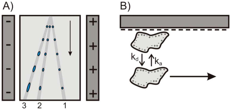
Figure 5.
(A) Schematic illustrating three hypothetical flow paths through a μFFE separation channel. Analyte 1 does not interact with the separation channel surface. Analytes 2 and 3 interact with the surface with increasing affinity giving rise to temporal broadening. (B) Illustration of the adsorption/desorption equilibrium of an analyte interacting with the glass surface of the separation channel. Note that the analyte is immobilized while adsorbed onto the surface. (Reproduced from reference 70 with permission)

