Abstract
Spatial-light-modulators (SLM) are increasingly used as active elements in adaptive optics (AO) systems to simulate optical corrections, in particular multifocal presbyopic corrections. In this study, we compared vision with lathe-manufactured multi-zone (2-4) multifocal, angularly and radially, segmented surfaces and through the same corrections simulated with a SLM in a custom-developed two-active-element AO visual simulator. We found that perceived visual quality measured through real manufactured surfaces and SLM-simulated phase maps corresponded highly. Optical simulations predicted differences in perceived visual quality across different designs at Far distance, but showed some discrepancies at intermediate and near.
OCIS codes: (260.0260) Physical optics; (330.0330) Vision, color, and visual optics; (330.4875) Optics of physiological systems; (330.5370) Physiological optics; (220.1010) Aberrations (global); (220.1080) Active or adaptive optics
1. Introduction
Spatial Light Modulators (SLM) are increasingly used as active elements [1, 2] to simulate different optical corrections in Adaptive Optics (AO) visual simulators. As opposed to deformable mirrors (DM), liquid crystal on silicon (LCoS)-SLMs are capable of reproducing abrupt phase maps, through the use of wrapped phase representations, increasing the device effective stroke [3, 4]. On the other hand, LCoS-SLMs have a lower response speed, present artifacts due to diffraction effects, generally require the use of polarized light and their behavior is wavelength-dependent due to the dispersion properties of the liquid crystal and the phase wrapping [4, 5].
AO visual simulators based on SLMs have been used for sensing and compensating of optical aberrations in ophthalmic applications [2, 5–7]. One of the most interesting application of the AO visual simulators based on LCoS-SLMs is their possibility to simulate and test vision on patients at different distances under complex multifocal presbyopic refractive corrections, such bifocal and trifocal corrections [8], bifocal, trifocal and tetrafocal, angular and radially segmented corrections [9], simulation of corneal inlays [10], or spherical aberration inducing corrections [11, 12]. There have also been some attempts to simulate diffractive corrections using SLMs [13]. Two-channel Simultaneous Vision Simulators have also made use of SLMs (in transmission) to simulate bifocal corrections with angularly [14], radially and hybrid pupillary distributions for near and Far [15]. Visual simulations using these systems have revealed significant differences in visual perception of patients with the different designs. Some lens design preferences were consistent across individuals (and to a large extent independent on the patient’s eyes aberrations, as the preferences for particular designs remained similar when the eye’s aberrations are AO-corrected [9]), whereas others were patient-specific (i.e. bias to particular orientations in bifocal angularly segmented designs [14]).
These studies indicate the value of using visual simulators to select the multifocal design that is better suited for a patient before lenses are fitted or implanted in a patient’s eye. They also allow investigating new multifocal lens designs and assessing the relative contributions of the native optics and neural effects on the performance of multifocal lenses at the patient level. A question often raised when using phase-only reflective SLMs to represent a certain design is the extent to what they truly represent a real lens. Differences may be expected arising from resolution limitations and diffraction artifacts in the SLM, and from manufacturing limitations in the physical lens.
In this study, we compared visual perception and optical quality with lathe-manufactured multi-zone multifocal surfaces and through equivalent phase maps simulated with an LCoS-SLM in a custom developed AO visual simulator.
2. Materials and methods
Vision was tested in subjects through six lathe-manufactured multizone multifocal surfaces and through similar phase maps simulated using a phase-only reflective LCoS-SLM in a polychromatic AO visual simulator, while AO-correcting HOAs of the subjects. Optical quality with the six designs was also evaluated by means of on-bench measurements and simulations using Visual Strehl-based metrics.
2.1 Subjects
Five young subjects (ages ranging from 25 to 32 years, mean 28.5 ± 0.14 years) participated in the study. The spherical error was −1.4 ± 0.2 D, and the average astigmatism was −0.2 ± 0.1D.
All participants were acquainted with the nature and possible consequences of the study and provided written informed consent. All protocols met the tenets of the Declaration of Helsinki and were previously approved by the Spanish National Research Council (CSIC) Ethical Committee.
2.2 Multifocal designs
Six different refractive multifocal designs, described in detail in previous works from our laboratory [9, 16, 17], were evaluated experimentally in the form of SLM-simulated phase maps and manufactured (freeform lathe) phase plates. The refractive multizone segmented phase designs consisted of N-zones with varying optical power ranging from 0 D to + 3 D across the lens in equal steps between the zones. In Zernike terms, defocus varied sequentially and linearly across zones between 0 and −3.89 μm in a 6 mm pupil, equivalent to a dioptric power change from + 0 D for Far distance correction to + 3.0 D as near addition. The six multifocal designs are split into angular and radially segmented designs.
The angular lenses featured N = 2, 3 and 4 zones (2ANG, 3ANG and 4ANG, respectively) of varying power across equi-sized sectors. To replicate more realistic manufacturing conditions, a transition zone was incorporated to smooth the phase change between the different 3- and 4-angular segments (5 degrees). The radial lenses featured N = 2, 3 and 4 zones (2RAD, 3RAD and 4 RAD, respectively) of varying power, where the zones are equal-area concentric regions. The radial lenses also have a transition zone between the zones corresponding to the diamond tool radius. The diameter of each lens was 6 mm. The area of each zone was constant in all cases.
Matlab routines were used to numerically simulate the multizone segmented phase designs, which were later programmed in a reflective phase-only LCoS-SLM and manufactured in a freeform lathe.
SLM-phase maps generation
Each phase map was defined by the wavefront in each zone and a set of complementary masks (radial or angular, 2, 3 and 4 zones) that equals 1 in the corresponding zone and 0 elsewhere [17]. A wrapping process [18, 19] was applied to the phase patterns to achieve a maximum phase difference of 2π defined by the calibration of the SLM. The generated pattern is a grey-scale image, where each level of grey corresponds to a certain phase difference between 0 and 2π. Images were generated for a 6-mm pupil at the pupil plane where the SLM is placed.
Surface manufacturing
Phase plates were manufactured in a four-axis Nanocam 650 FG free-form lathe (Moore Nanotechnology Systems, Swanzey, NH). Polar coordinate sag tables of each of the lenses were generated in custom software and provided to the lathe [16]. Each lens was lathed into one PMMA blank using a diamond tool with a 0.5-mm tool radius. An optical profilometric microscope (PLµ, Sensofar, Barcelona, Spain) [20], mounted on a vibration-isolated table, was used to characterize the surface profile of the lathe-manufactured phase plates.
2.3 Polychromatic adaptive optics system
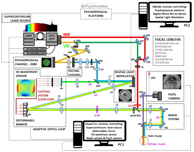
Visual tests were performed in a custom-developed AO system at the Visual Optics and Biophotonics Lab (Institute of Optics, Spanish National Research Council), described partially in previous publications [9, 21, 22]. In this system, the visual stimulus is seen through a DM (which we used to correct the subject’s native aberrations) and a reflective phase-only LCoS-SLM (which we used to simulate the multifocal designs). Specifically, for the current study, we incorporated an alternative channel to insert the manufactured surfaces. The DM, LCoS-SLM and surfaces were placed in pupil conjugate planes. Tests were done upon measurement (with Hartman-Shack aberrometry) and correction (with a deformable mirror) of the HOAs of the subject and the system.
The current configuration of the system (shown in a schematic diagram in Fig. 1) is formed by six different channels: (1) The Illumination-Channel, with light coming from a supercontinuum laser source (SCLS, SC400 femtopower 1060 supercontinuum laser, Fianium Ltd, United Kingdom) which delivers a supercontinuum spectrum, spanning from below 450 nm to beyond 1100 nm (in our system configuration) and, in combination with a dual acousto‐optic tunable filter (AOTF) module (Gooch & Housego, United Kingdom), operated by RF drivers, which is used to automatically select the desired wavelengths in visible or near infrared light. (2) The AO-Channel, consisting of the Hartmann-Shack wavefront sensor (microlens array 40x32, 3.6 mm effective diameter, centered at 1062 nm; HASO 32 OEM, Imagine Eyes, France) and the electromagnetic deformable mirror (52 actuators, 15-mm effective diameter, 50-µm stroke; MIRAO, Imagine Eyes, France), to measure and correct HOAs, respectively. (3) The SLM-Channel, consisting of the reflective phase-only LCoS-SLM (SLM; VIS; Resolution: 1920x1080; Pixel pitch: 8.0 µm; Holoeye Photonics AG, Germany) to the system and generates the multizone segmented phase design. (4) The Testing-Channel, added to the system for this study, allows evaluating the phase-plates inserted in a conjugate pupil plane, incorporated to the system by a relay of lenses (L11 and L12). The 6 different lathe-manufactured multifocal surfaces were mounted in a rotating filter wheel to allow rapid transition between designs. The DM, the wavefront sensor, the SLM and the testing plane are conjugate to the pupil by different relays of lenses. Magnification from the pupil is 2x to the deformable mirror, 1x to the SLM and the testing plane, and 0.5x to the wavefront sensor. (5) The main component of the Psychophysical-Channel (PSY-Channel) is a Digital Micro-Mirror Device (DMD) (DLP® Discovery 4100 0.7 XGA, Texas Instruments (USA)), placed in a conjugate retinal plane, and used to display visual stimuli with a 1.62 deg angular subtend. The DMD was monochromatically (555 nm) illuminated with light coming from the SCLS. A holographic diffuser (HD) placed in the beam path breaks the coherence of the laser providing a uniform illumination of the stimulus. (6) The Pupil Monitoring-Channel, which consists of a camera (DCC1545M, High Resolution USB2.0 CMOS Camera, Thorlabs GmbH, Germany) conjugated to the eye’s pupil by means of a 105-mm focal length objective lens (L12). In addition, a Badal system corrects for defocus in AO-, SLM-, Testing- and Psychophysical-Channels. Two automatized shutters allow simultaneous illumination of the eye (S1) and the stimulus (S2).
Fig. 1.
Custom-made polychromatic adaptive-optics setup. Schematic diagram of the VioBio Lab AO II system with the different channels in its current configuration (November, 2015): the Illumination-Channel (red line), the AO-Channel (green line); the SLM-Channel (yellow line); the Testing-Channel (blue line); the Psychophysical-Channel (orange line) and the Pupil Monitoring-Channel (purple line). NIR: near infrared light; VIS: visible light; RP: retinal plane; PP: pupil plane; BS: beam splitter; S: shutter; L: lens; M: mirror; HM: hot mirror; POL: polarizer; E-RP: retinal pinhole; AP-PP: artificial pupil; VS-P: variable size pupil.
Subjects were stabilized using a dental impression and the eye's pupil was aligned to the optical axis of the instrument (using an x-y-z stage moving a bite bar) using the line of sight as a reference, while the natural pupil is viewed on the monitor. To ensure constant pupil diameter during the measurements, a 6-mm artificial pupil was placed in a conjugate pupil plane.
All optoelectronic elements of the system were automatically controlled and synchronized using custom-built software programmed in Visual C + + and C# (Microsoft). The custom-developed routines make use of the manufacturer’s Software Development Kit for Hartmann-Shack centroiding detection and wave aberration polynomial fitting.
2.4 Experimental procedure
Measurements were performed monocularly, under natural viewing conditions, in a darkened room, under cycloplegia (by instillation of Tropicamide 1%, 2 drops 30 minutes prior to the beginning of the study, and 1 drop every 1 hour). Before the measurement, subjects were instructed on the nature of the experiment and performed some trial runs.
Astigmatism and high order aberrations (HOAs) were measured and corrected in a closed-loop operation (λ = 827 nm). The subject was then asked to adjust the Badal system position to achieve best subjective focus. The state of the mirror that achieved the correction was saved and applied during the measurements. Psychophysical measurements were performed under full static AO-corrected aberrations and best spherical refraction error correction, at Far, intermediate and near distances simulated with the Badal system (0 D, + 1.5 D and + 3.0 D relative best distance spherical correction, respectively). VA measurements were performed at Far and near distance.
Subjects viewed the psychophysical stimulus generated by the Digital Micro-Mirror Device (DMD), illuminated monochromatically at 555 nm, through the SLM-simulated phase maps or the lathe-manufactured surfaces and performed the corresponding psychophysical test (perceived visual quality or visual acuity).
2.5 Perceived visual quality
Images generated by multifocal optics vary on more than one perceptually identifiable dimension [23], thus the use of global perception metrics [9, 24, 25] is well suited to characterize visual perception with multifocal designs. In this study, the psychophysical paradigm consisted on a perceptual scoring of the stimuli viewed through the different SLM-simulated and the lathe-manufactured multifocal surfaces, in series of 60 trials. The stimuli consisted of a binary noise pattern with sharp edges at random orientations. The binary noise pattern was digitally produced from a uniform noise distribution spatially filtered with an annular filter in the frequency domain (inner radius: 3 cycles/deg; outer radius: 6 cycles/deg), that was later transformed to a binary image and smooth by means of a Gaussian function [9, 26]. A new stimulus was generated on each trial with a different noise pattern, so that edges at all orientations were presented over the course of the experiment. Patterns and viewing distances were randomly selected. For each test stimulus presented (for 500 ms) the subject was instructed to grade the image quality from very sharp to very blurred in a 6-point scale using corresponding keys in a response system (1-very blurred, 2-blurred, 3-not so blurred....). A score, of 0 to 5, was posteriorly assigned, based on the grading. The measurements were repeated 3 times. This method has been used and shown to be useful in determining subjective visual quality with multifocal correction in previous studies [24, 25].
2.6 Visual acuity
Visual acuity (VA) was measured using an 8-Alternative Forced Choice (8AFC) [27] procedure with Tumbling E letters and a QUEST (Quick Estimation by Sequential Testing) algorithm programmed with the Psychtoolbox package [28] to calculate the sequence of the presented stimulus (letter size and orientation) in the test following the subject’s response. Subjects had to determine the orientation of the letter E, through the SLM-simulated phase maps or the lathe-manufactured surfaces, while aberrations were AO-corrected with the deformable mirror. The QUEST routine for each VA measurement consisted of 40 trials, each one presented for 0.5 seconds, where the threshold criterion was set to 75%. The threshold, VA measurement, was estimated as the average of the 10 last stimulus values. Visual acuity was expressed in terms of decimal acuity (logMAR = -log10[decimal acuity]) [29].
2.7 Estimated optical quality
Through-focus optical quality for the different 6-zone angular and radial segmented phase designs was calculate from the wave aberration of each eye in all conditions (different multizone angular and radial segmented phase designs, with natural and AO-corrected aberrations). The measured residual aberrations after AO-correction of the five subjects, the phase map programmed in the SLM, and the phase-plate phase map, derived from profilometric data, were used in the optical simulations.
The Visual Strehl (VS) was used as an optical quality metric, estimated as the volume between the Modulation Transfer Function (MTF) of the system, and a general neural transfer function [30, 31]. The MTF was estimated from the pupil function using Fourier Optics. The following parameters were computed from the through-focus VS curves: (1) Area under VS curves in a 6.0 D dioptric range; (2) Dioptric range above a certain threshold (0.06); (3) VS at far, intermediate and near distance (0 D, + 1.5 D and + 3.0 D, respectively) [9]. The response of an “ideal observer”, purely responding on optical grounds to the same psychophysical test performed on subjects, was calculated in all eyes, conditions and distances. Scores (ranging from 0 to 5) were based on the VS values, normalized to the maximum VS value, using a similar approach to that of the psychophysical paradigm for perceptual scoring. All calculations were performed for a 6-mm pupil diameter.
2.8 On-bench tests
The optical quality of both, lathe-manufactured surfaces and SLM-simulated phase maps, was evaluated on bench in the same AO system, using an artificial eye provided with an objective lens (50.8 mm) and a CCD camera (DCC1545M, High Resolution USB2.0 CMOS Camera, Thorlabs GmbH, Germany) acting as a “retina”, in place of the subject’s eye. An E-letter (1.62-deg subtend) was displayed in the Digital Micro-Mirror Device (DMD), illuminated with 555 nm light from the SCLS. Series of through-focus images (+1.00 to −4.00 D, in 0.25D steps) of the stimulus were collected in the artificial eye with all patterns, while the aberrations of the system were AO-corrected, for 6-mm pupil diameter. The optical quality metric was the image correlation of the collected image with the reference image (same E-letter, through monofocal optics in focus). Through focus optical quality curves were compared across patterns and lens type (lathe-manufactured surface and SLM-simulated phase maps), and the values at near, intermediate and far were used to rank the patterns.
2.9 Data analysis
Perceptual scoring results obtained for the different conditions (6 different multifocal patterns, SLM-simulated phase maps or lathe-manufactured surfaces, at 3 different distances) were compared. Results from optical simulations and on-bench tests were presented in a similar manner as the experimental perceptual scoring results.
Statistical analysis was performed with SPSS software (IBM) and Minitab 17.3.1 (Minitab) to test differences across results with SLM-simulated phase maps and lathe-manufactured surfaces.
3. Results
Perceptual scoring of a monochromatic binary noise stimulus and VA were measured in patients with six multizone multifocal phase patterns through both, lathe-manufactured surfaces and equivalent phase maps simulated with an SLM, in an AO visual simulator, while AO-correcting the HOAs of the subjects. Residual HOAs of the subjects upon AO-correction were lower than 0.07 μm, ensuring that all subjects performed the experiments under nearly identical optics.
3.1 Lathe-manufactured surfaces and SLM-simulated phase maps
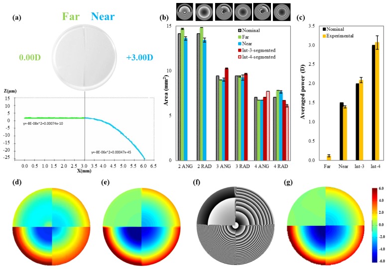
The six lathe-manufactured surfaces were characterized using non-contact microscopy-based optical microscopy (PLµ, Sensofar, Barcelona, Spain). Figure 2(a) shows an example of a photograph of a 2ANG phase plate (top) and the corresponding optical profile across a horizontal half-meridian (bottom). For each lens, the optical profile was analyzed and the areas of the different zones were calculated and compared with the nominal values. The resulting phase map was obtained and compared with the SLM-simulated phase map. Figure 2(b) shows the measured areas of the different lathe-manufactured surfaces for far (green solid bars), intermediate-3-segmented (red solid bars), intermediate-4-segmented (red dashed bars), and near distance (blue solid bars) zones, and of the corresponding nominal areas of those designs (black dashed bars). On average, discrepancies between experimental and nominal areas were below 2% in all cases. In terms of dioptric power, the averaged power for all zones falls within 0.1% of difference with respect to the nominal values for the same zones (Fig. 2(c)).
Fig. 2.
(a) 2ANG lathe-manufactured phase plate (top) and its corresponding lathe-manufactured surface profile (bottom, measured with non-contact profilometry) for far (green) and near distance (blue). (b) Areas of the different lathe-manufactured phase plate for far (green solid bars), intermediate-3-segmented (red solid bars), intermediate-4segmented (red dashed bars), and near distance (blue solid bars) and for the nominal areas of those designs (black dashed bars). Error bars stand for experimental error during measurements with the profilometer. (c) Dioptric power of the different optical zones of the lathe-manufactured phase plate for far, near, intermediate for 3-segmented and intermediate for 4-segmented (yellow bars) and their corresponding nominal values (black bars). Error bars stand for experimental error during measurements with the profilometer. (d) Phase map obtained from profilometric measurements of an example surface-modulated plate (4ANG); (e) Intended phase map for 4ANG in the SLM (before wrapping); (f) Wrapped phase map in the SLM; (g) Measured phase map induced by the SLM (composite from Hartmann Shack measurements of equivalent pure defocus phase maps). Color bar scale is in microns. Data are for 6-mm pupil diameter.
Figure 2(d)-2(g) shows an example of the generated wavefront with either the lathe-manufactured surface or the SLM-simulated phase map with 4ANG design. The figure shows the phase map obtained from profilometric measurements of the 4ANG phase plate (d), the intended phase map for the SLM (before wrapping) (e), the wrapped phase map for the SLM (f), the measured phase map induced with the SLM (composite from Hartmann-Shack measurements obtained for induced pure defocus of 0.0, + 1.0, + 2.0, and + 3.0 D) (g).
Figure 3 shows the results of on-bench optical quality measurements with surfaces and SLM-simulated phase maps. Figure 3(a) shows an example of the through-focus image series obtained for 3ANG design in the form of surface-modulated plate (upper row) and mapped with the SLM (lower row). Figure 3(b) shows the corresponding through-focus optical quality (image correlation metric) for the surface-modulated phase plate (green) and the SLM (blue). Figure 3(c) shows through-focus optical quality (image correlation) for all 6 designs with surface-modulated plates, and Fig. 3(d) for the SLM-simulated phase maps.
Fig. 3.
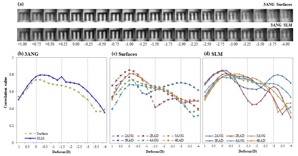
(a) Example of the through-focus image series obtained for 3ANG design in the form of lathe-manufactured surface (upper row) and SLM-simulated phase map (lower row). (b) Corresponding through-focus optical quality (image correlation metric) for those two series of images (blue for lathe-manufactured surface and green for SLM-simulated phase map). (c) Through-focus optical quality (image correlation metric) for all 6 designs with surfaces-modulated plates. (d) Through-focus optical quality (image correlation metric) for all 6 designs with SLM-simulated phase maps. Data are for 6-mm pupil diameter.
3.2 Perceived visual quality
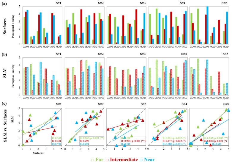
The results of the perceptual scoring from the five subjects are summarized in Fig. 4. Perceptual scoring obtained with lathe-manufactured surfaces (upper row, solid bars), with SLM-simulated phase maps (middle row, dashed bars) and the correlations between them (lower row) for far (green), intermediate (red) and near (blue) distance upon AO-correction of HOAs of the subjects. Similar general trends are found with lathe-manufactured surfaces and SLM-simulated phase maps.
Fig. 4.
Perceptual scoring with each multifocal pattern from all 5 subjects for far (green), intermediate (red) and near (blue) distance with (a) lathe-manufactured surfaces and (b) SLM-simulated phase maps. (c) Correlations between perceptual scores for lathe-manufactured surfaces and SLM-simulated phase maps for all subjects. Statistically significant correlations (*p < 0.05; **p<0.005) are noted in each graph.
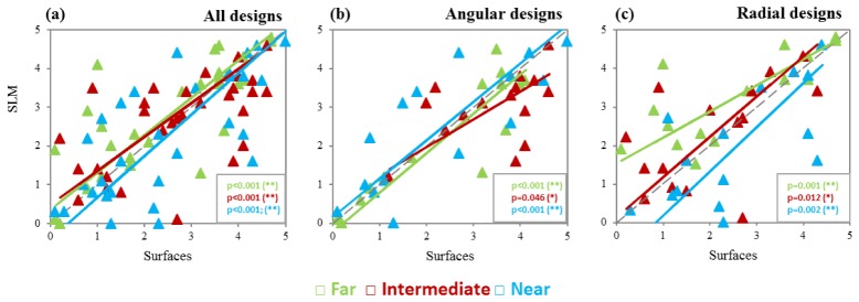
Figure 5 shows the correlation between the perceived visual quality with the SLM-simulated phase maps and with the lathe-manufactured surfaces for all subjects and all designs (left), all angular designs (center) and all radial designs (right) for far (green), intermediate (red) and near (blue) distance. The correlations were statistically significant (p<0.05) for all conditions and all testing distances.
Fig. 5.
Correlation between the relative perceived visual quality results obtained with the SLM-simulated phase maps and the lathe-manufactured surfaces for all subjects and all designs (left), all angular designs (middle) and all radial designs (right) for far (green), intermediate (red) and near (blue) distance, and calculated orthogonal regression (solid lines). Statistically significant orthogonal correlations (*p < 0.05; **p<0.005) are noted in each graph.
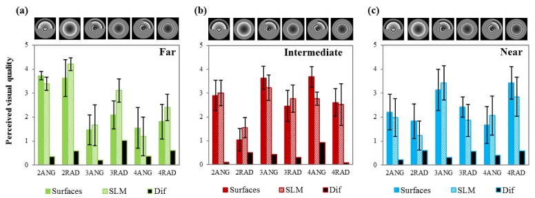
Figure 6 shows the average (across 5 eyes) perceived visual quality (perceptual scoring) with lathe-manufactured surfaces (solid bars) and SLM-simulated phase maps (dashed bars) for far (green), intermediate (red) and near (blue) distance after AO-correction of HOAs of the subjects. Black bars show the difference between both conditions.
Fig. 6.
Average relative perceived visual quality (perceptual scoring) with lathe-manufactured surfaces (solid bars) and SLM-simulated phase maps (dashed bars) for far (green), intermediate (red) and near (blue) and their corresponding difference (black bars). Data average data across 5 subjects, for 6-mm pupils and AO-correction of the HOAs of the subjects. Error bars stand for standard deviation across subjects.
In general, there is good agreement between the relative perceived visual quality obtained with the lathe-manufactured surfaces and the SLM-simulated phase maps with similar trends across distances. The higher differences occurred for 2RAD (0.58), 3RAD (1.02) and 4RAD (0.60) for far vision; 2RAD (0.5) and 4ANG (0.92) for intermediate vision; and 2RAD (0.60), 3RAD (0.56) and 4RAD (0.58) for near vision.
3.3 Perceived vs. optical quality
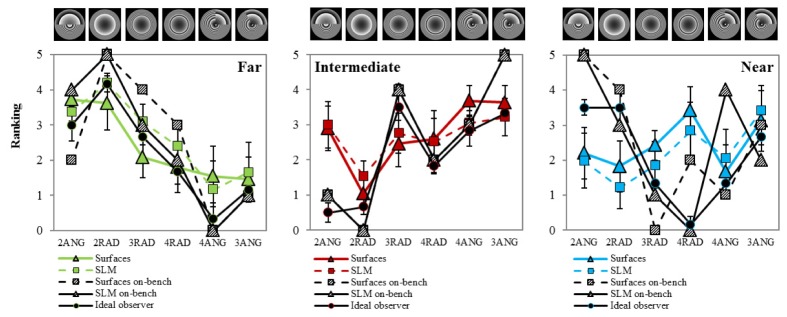
For comparison between optical (ideal observer and correlation metrics) and perceived visual quality with the SLM-simulated phase maps and lathe-manufactured surfaces, the six patterns were organized according to the average scored, from the least preferred to the most preferred pattern on average by the “ideal observer” with the lathe-manufactured surfaces and at far distance. The ranking was as follows: 2ANG was the most preferred followed by 2RAD, 3RAD, 4RAD, 4ANG and 3ANG (as illustrated by the images on top of the graphs in Fig. 7).
Fig. 7.
Average rankings of multifocal patterns for the 3 testing distances (far: green, intermediate: red and near: blue) from experimental results from lathe-manufactured surfaces (squares), SLM-simulated phase maps (triangles) and optical predictions (circles), and from on-bench measurements from lathe-manufactured surfaces (dashed black squares) and from phase maps (dashed black triangles). Error bars stand for standard deviation across subjects.
Figure 7 shows the ranking of patterns for the perceived visual quality test performed experimentally with lathe-manufactured surfaces (squares) and SLM-simulated phase maps (triangles), the corresponding optical predictions (circles) based on the responses of the “ideal observer” using the ideal patterns and measured residual aberrations, and the correlation metric from the through-focus series of on-bench images (dash symbols), for the 3 testing distances (far: green, intermediate: red and near: blue). In general, there is very good agreement between both, lathe-manufactured surfaces and SLM-simulated phase maps, responses for all distances (RMS ranking difference at Far: 0.21; Intermediate: 0.14; and Near: 0.18). The optical simulations predicted well the results of both lathe-manufactured surfaces (RMS ranking difference at Far: 0.24; Intermediate: 0.42; and Near: 0.58) and SLM-simulated phase maps (RMS ranking difference at Far: 0.2; Intermediate: 0.38; and Near: 0.58). There are not statistically significant differences in the ranking between the phase plate and SLM-simulated phase maps. The only significant differences between the experimental results and those purely predicted on optical grounds occurred for the 2ANG at intermediate (p = 0.241) and near and 4RAD at near (p = 0.381).
Image correlation metric for both, lathe-manufactured surfaces and SLM-simulated phase maps also follow similar trends than optical predictions (RMS difference in ranking for lathe-manufactured surfaces at Far, 0.64; Intermediate, 0.44; and Near, 0.57; RMS ranking difference for SLM-simulated phase maps at Far, 0.48; Intermediate, 0.44; and Near, 0.44).
Average standard deviation in the scores (averaged across patterns and subjects) was higher for the psychophysical measurements (0.622 for surface-modulated and 0.603 for SLM) than for the computations based on the ideal observer (0.007), which used the measured residual aberrations, but was relatively small compared to the 0-5 score scale (Fig. 6).
Similar trends in pattern ranking were found for the psychophysical experiments in subjects, simulations based on the ideal observer and on-bench optical data, particularly at Far and Intermediate. Psychophysical ranking for 2ANG patterns (both, for lathe-manufactured surfaces and SLM) outperform predictions from ideal observer simulations and from optical bench measurements at intermediate, and Psychophysical ranking for 2ANG and 2RAD underperform predictions at near. Difference in performance of surface-modulated plates and SLM only occurred for on-bench measurements of 4RAD and 4ANG.
Pattern ranking from on physical on-bench measurements showed high similarity between surface-modulated and SLM-simulated phase maps for the on-bench experiment (RMS difference = 0.17), and real psychophysical measurements with both lathe-manufactured surfaces and SLM-simulated phase maps (RMS difference = 0.63 and 0.54, respectively), in a 0 to 5 range. The average RMS difference (across patterns, subjects and distances) between model (ideal observer) and psychophysical ranking results was 0.401 and 0.375 for lathe-manufactured surfaces and SLM, respectively, and between model and on-bench results was 0.548 and 0.419 for lathe-manufactured surfaces and SLM, respectively, in a range of 0-5. This indicates that, in general, the ideal observer metric (as well as the physical on bench measurements) is a good predictor of the psychophysical performance.
3.5 Visual acuity
Figure 8 shows the average decimal visual acuity (VA) across subjects for all designs with lathe-manufactured surfaces (solid bars) and SLM-simulated phase maps (dashed bars), for far (green bars) and near (blue) distance. There are not statistically significant differences between VA with SLM-simulated phase maps and lathe-manufactured surfaces at any distance (one-way ANOVA; p>0.05). Intersubject variability is lower for lathe-manufactured surfaces than for SLM-simulated phase maps (Lathe-manufactured surfaces: Far, 0.014 ± 0.002; Near, 0.024 ± 0.003; SLM-simulated phase maps: Far, 0.028 ± 0.006; Near, 0.014 ± 0.003).
Fig. 8.
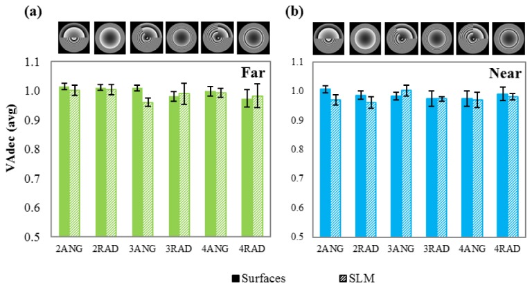
Average decimal visual acuity (VA) for all 5 subjects and all designs with lathe-manufactured surfaces (solid bars) and SLM-phase maps (dashed bars) and for far (green bars) and near (blue) distance. Error bars stand for standard deviation across subjects.
4. Discussion
AO visual simulators are increasingly used to simulate visual performance with multifocal lens designs [8–12, 14, 15]. In particular, LCoS-SLMs allow representing diffractive and segmented refractive designs, although the correspondence of this simulation with that obtained from physically manufactured lenses tested on the same eyes, had not been, to our knowledge, demonstrated. In this study, we compared vision through real lathe-manufactured surfaces and SLM-simulated phase maps, in a custom-developed AO visual simulator, in terms of relative perceived visual quality (lens design ranking) and of visual acuity. The same angularly and radially segmented profiles presented in a previous study were selected [9].
Previous studies found consistent differences in perceived visual quality with segmented patterns, which depended both on the radial or angular distribution of the far-intermediate and near zones and the number of zones respectively [9, 17]. The findings are consistent with those of the current study (angular, and fewer number of zones generally preferred), both with SLM-simulated and surface-modulated phase maps, indicating that these differences in perceived visual quality across patterns are in fact associated to the design and not an artifact of the SLM simulation. As in previous works [14], we also found that a perceived visual quality test is more sensitive in detecting perceptual differences across designs that a high contrast visual acuity task.
On average there was a good agreement between the perceived visual quality obtained with lathe-manufactured surfaces and SLM-simulated phase maps at all distances (RMS ranking difference at Far: 0.21; Intermediate: 0.14; and Near: 0.18) (Fig. 7), and are only slightly larger for the radial than for the angular designs (averaged perceptual scoring: 0.54 vs. 0.36, respectively) (Fig. 6). For intermediate vision, surface-modulated angular designs (3- and 4-ANG) provided better perceived visual quality than radial designs (averaged perceptual scoring: 3.63 and 3.68 vs. 3.22 and 2.76 respectively). The relatively higher perceived visual quality with angular compared to radial designs found for surface-modulated plates (Fig. 6, Far), might be associated to manufacturing artifacts, arising from the diamond turning process during the phase plate lathing: the angular lenses needed to be cut at a much slower RPM so that that tool translation speed would be able to make the jump from each zone to the next as the lens is rotated. Slowing down the RPM increases the introduction of tool marks onto the lens [16]. These submicron surface grooves can introduce diffraction and scattering effects in the visual testing and therefore affect the perceived visual quality through the lenses. In our case, on average discrepancies in zones distribution between experimental and nominal values for the different areas are below 2% in all cases. However, discrepancies are slightly higher for 3- and 4- segmented angular than for radial designs (0.73% and 0.54% vs. 0.69% and 0.43%, respectively).
The optical simulations based on an ideal observer ranking the patterns according to a Visual Strehl metric predicts well the results of both lathe-manufactured surfaces (RMS difference in ranking at Far: 0.24; Intermediate: 0.42; and Near: 0.58) and SLM-simulated phase maps (RMS ranking difference at Far: 0.2; Intermediate: 0.38; and Near: 0.58) (Fig. 7). The optical predictions matched well the experimental pattern ranking and scoring in most cases but underestimated perceived quality with 2ANG at intermediate and 4RAD at near, and overestimated 2ANG and 2RAD at far. We can speculate on the reasons for the discrepancy relating to the simplicity of the VS as an optical quality metric (which ignores orientational aspects) or neural factors (including neural adaptation effects which present orientation bias [32]). On-bench optical evaluation of surface-modulated plates and SLM-simulated phase maps, expressed as rankings, is in close agreement with predictions from the ideal observer at far, intermediate and near, except for 4RAD surfaces and 4ANG SLM-simulated phase maps at near. The reasons why the optical predictions are closer to the perceptual results for far than for intermediate and near are not known, but suggest that a true evaluation of the through-focus performance with different designs should not entirely rely on optical simulations.
The high similarity in perceived visual quality assessed in patients with real lathe-manufactured surfaces and phase maps simulated with a Spatial Light Modulator demonstrates that visual simulators are excellent tools to test vision programing the designs on the SLM allowing rapid assessment of different designs before manufacturing. The current study addressed segmented designs, and used monochromatic stimuli. Future studies should address diffractive designs (also possibly mapped in the SLM), and real polychromatic stimuli, where limitations associated to chromatic and diffractive artifacts may result in discrepancies between real and SLM-simulated lenses, which should be quantified.
Acknowledgments
Authors want to thank Laura Barrios from the Scientific Calculus Center of the Spanish National Research Council (CSIC) for help with the statistical analysis within the study, and Vyas Akondi (VioBio Lab, Institute of Optics, CSIC) for insights in the correlation metric for on-bench image data analysis.
Funding
This research has received funding from the European Research Council ERC-2011-AdG-294099. This study was also supported by Spanish Government grants FIS2014-56643-R to SM, and CSIC JAE Predoctoral Programs & MICINN FPU Predoctoral fellowship to MV.
References and links
- 1.Dou R., Giles M. K., “Closed-loop adaptive-optics system with a liquid-crystal television as a phase retarder,” Opt. Lett. 20(14), 1583–1585 (1995). 10.1364/OL.20.001583 [DOI] [PubMed] [Google Scholar]
- 2.Love G. D., “Wave-front correction and production of Zernike modes with a liquid-crystal spatial light modulator,” Appl. Opt. 36(7), 1517–1520 (1997). 10.1364/AO.36.001517 [DOI] [PubMed] [Google Scholar]
- 3.Martínez-Cuenca R., Durán V., Arines J., Ares J., Jaroszewicz Z., Bará S., Martínez-León L., Lancis J., “Closed-loop adaptive optics with a single element for wavefront sensing and correction,” Opt. Lett. 36(18), 3702–3704 (2011). 10.1364/OL.36.003702 [DOI] [PubMed] [Google Scholar]
- 4.Zhang Z. Y., Chu Z, “Fundamentals of phase-only liquid crystal on silicon (LCOS) devices,” Light Sci. Appl. 3, e213 (2014). [Google Scholar]
- 5.Prieto P., Fernández E., Manzanera S., Artal P., “Adaptive optics with a programmable phase modulator: applications in the human eye,” Opt. Express 12(17), 4059–4071 (2004). 10.1364/OPEX.12.004059 [DOI] [PubMed] [Google Scholar]
- 6.Thibos L. N., Bradley A., “Use of liquid-crystal adaptive-optics to alter the refractive state of the eye,” Optom. Vis. Sci. 74(7), 581–587 (1997). 10.1097/00006324-199707000-00028 [DOI] [PubMed] [Google Scholar]
- 7.Vargas-Martín F., Prieto P. M., Artal P., “Correction of the aberrations in the human eye with a liquid-crystal spatial light modulator: limits to performance,” J. Opt. Soc. Am. A 15(9), 2552–2562 (1998). 10.1364/JOSAA.15.002552 [DOI] [PubMed] [Google Scholar]
- 8.Manzanera S., Prieto P. M., Ayala D. B., Lindacher J. M., Artal P., “Liquid crystal Adaptive Optics Visual Simulator: Application to testing and design of ophthalmic optical elements,” Opt. Express 15(24), 16177–16188 (2007). 10.1364/OE.15.016177 [DOI] [PubMed] [Google Scholar]
- 9.Vinas M., Dorronsoro C., Gonzalez V., Cortes D., Radhakrishnan A., Marcos S., “Testing vision with angular and radial multifocal designs using Adaptive Optics,” Vision Res. 16, S00426989 (2016). [DOI] [PubMed] [Google Scholar]
- 10.Tabernero J., Schwarz C., Fernández E. J., Artal P., “Binocular visual simulation of a corneal inlay to increase depth of focus,” Invest. Ophthalmol. Vis. Sci. 52(8), 5273–5277 (2011). 10.1167/iovs.10-6436 [DOI] [PubMed] [Google Scholar]
- 11.Schwarz C., Cánovas C., Manzanera S., Weeber H., Prieto P. M., Piers P., Artal P., “Binocular visual acuity for the correction of spherical aberration in polychromatic and monochromatic light,” J. Vis. 14(2), 8 (2014). 10.1167/14.2.8 [DOI] [PubMed] [Google Scholar]
- 12.Manzanera S., Artal P., “Minimum change in spherical aberration that can be perceived,” Biomed. Opt. Express 7(9), 3471–3477 (2016). 10.1364/BOE.7.003471 [DOI] [PMC free article] [PubMed] [Google Scholar]
- 13.Zhao L., Bai N., Li X., Ong L. S., Fang Z. P., Asundi A. K., “Efficient implementation of a spatial light modulator as a diffractive optical microlens array in a digital Shack-Hartmann wavefront sensor,” Appl. Opt. 45(1), 90–94 (2006). 10.1364/AO.45.000090 [DOI] [PubMed] [Google Scholar]
- 14.Radhakrishnan A., Dorronsoro C., Marcos S., “Differences in visual quality with orientation of a rotationally asymmetric bifocal intraocular lens design,” J. Cataract Refract. Surg. 42(9), 1276–1287 (2016). 10.1016/j.jcrs.2016.06.034 [DOI] [PubMed] [Google Scholar]
- 15.Dorronsoro C., Radhakrishnan A., de Gracia P., Sawides L., Marcos S., “Perceived image quality with different experimentally simulated segmented bifocal corrections,” Biomed. Opt. Express 7, 4388–4399 (2016). 10.1364/BOE.7.004388 [DOI] [PMC free article] [PubMed] [Google Scholar]
- 16.E. LaVilla, M. Vinas, S. Marcos, and J. Schwiegerling, “Freeform Design of Multifocal Zone Plates,” in Imaging and Applied Optics 2015, OSA Technical Digest, ed. (Optical Society of America, 2015). [Google Scholar]
- 17.de Gracia P., Dorronsoro C., Marcos S., “Multiple zone multifocal phase designs,” Opt. Lett. 38(18), 3526–3529 (2013). 10.1364/OL.38.003526 [DOI] [PubMed] [Google Scholar]
- 18.D. G. Voelz, “Computational fourier optics: a MATLAB tutorial,” (SPIE, 2011). [Google Scholar]
- 19.Abdul-Rahman H. S., Gdeisat M. A., Burton D. R., Lalor M. J., Lilley F., Moore C. J., “Fast and robust three-dimensional best path phase unwrapping algorithm,” Appl. Opt. 46(26), 6623–6635 (2007). 10.1364/AO.46.006623 [DOI] [PubMed] [Google Scholar]
- 20.Dorronsoro C., Remon L., Merayo-Lloves J., Marcos S., “Experimental evaluation of optimized ablation patterns for laser refractive surgery,” Opt. Express 17(17), 15292–15307 (2009). 10.1364/OE.17.015292 [DOI] [PubMed] [Google Scholar]
- 21.Vinas M., Dorronsoro C., Cortes D., Pascual D., Marcos S., “Longitudinal chromatic aberration of the human eye in the visible and near infrared from wavefront sensing, double-pass and psychophysics,” Biomed. Opt. Express 6(3), 948–962 (2015). 10.1364/BOE.6.000948 [DOI] [PMC free article] [PubMed] [Google Scholar]
- 22.Vinas M., Dorronsoro C., Garzón N., Poyales F., Marcos S., “In vivo subjective and objective longitudinal chromatic aberration after bilateral implantation of the same design of hydrophobic and hydrophilic intraocular lenses,” J. Cataract Refract. Surg. 41(10), 2115–2124 (2015). 10.1016/j.jcrs.2015.11.009 [DOI] [PubMed] [Google Scholar]
- 23.Kollbaum P. S., Jansen M. E., Rickert M. E., “Comparison of patient-reported visual outcome methods to quantify the perceptual effects of defocus,” Cont. Lens Anterior Eye 35(5), 213–221 (2012). 10.1016/j.clae.2012.05.001 [DOI] [PubMed] [Google Scholar]
- 24.Radhakrishnan A., Dorronsoro C., Sawides L., Marcos S., “Short-term neural adaptation to simultaneous bifocal images,” PLoS One 9(3), e93089 (2014). 10.1371/journal.pone.0093089 [DOI] [PMC free article] [PubMed] [Google Scholar]
- 25.Dorronsoro C., Radhakrishnan A., Alonso-Sanz J. R., Pascual D., Velasco-Ocana M., Perez-Merino P., Marcos S., “Portable simultaneous vision device to simulate multifocal corrections,” Optica 3(8), 918–924 (2016). 10.1364/OPTICA.3.000918 [DOI] [Google Scholar]
- 26.Chen L., Singer B., Guirao A., Porter J., Williams D. R., “Image metrics for predicting subjective image quality,” Optom. Vis. Sci. 82(5), 358–369 (2005). 10.1097/01.OPX.0000162647.80768.7F [DOI] [PubMed] [Google Scholar]
- 27.W. H. Ehrenstein and A. Ehrenstein, “Psychophysical methods,” in Modern Techniques in Neuroscience Research, U. Windhorst, and H. Johansson, eds. (Springer, 1999), pp. 1211–1240. [Google Scholar]
- 28.Brainard D. H., “The Psychophysics Toolbox,” Spat. Vis. 10(4), 433–436 (1997). 10.1163/156856897X00357 [DOI] [PubMed] [Google Scholar]
- 29.Holladay J. T., “Proper method for calculating average visual acuity,” J. Refract. Surg. 13(4), 388–391 (1997). [DOI] [PubMed] [Google Scholar]
- 30.Marsack J. D., Thibos L. N., Applegate R. A., “Metrics of optical quality derived from wave aberrations predict visual performance,” J. Vis. 4(4), 8 (2004). 10.1167/4.4.8 [DOI] [PubMed] [Google Scholar]
- 31.Iskander D. R., “Computational aspects of the visual Strehl ratio,” Optom. Vis. Sci. 83(1), 57–59 (2006). 10.1097/01.opx.0000195563.82891.3b [DOI] [PubMed] [Google Scholar]
- 32.Sawides L., Marcos S., Ravikumar S., Thibos L., Bradley A., Webster M., “Adaptation to astigmatic blur,” J. Vis. 10(12), 22 (2010). 10.1167/10.12.22 [DOI] [PMC free article] [PubMed] [Google Scholar]


