Abstract
Here we report the direct observation and quantitative analysis of single redox events on a modified indium–tin oxide (ITO) electrode. The key in the observation of single redox events are the use of a fluorogenic redox species and the nanoconfinement and hindered redox diffusion inside 3-nm-diameter silica nanochannels. A simple electrochemical process was used to grow an ultrathin silica film (~100 nm) consisting of highly ordered parallel nanochannels exposing the electrode surface from the bottom. The electrode-supported 3-nm-diameter nanochannels temporally trap fluorescent resorufin molecules resulting in hindered molecular diffusion in the vicinity of the electrode surface. Adsorption, desorption, and heterogeneous redox events of individual resorufin molecules can be studied using total-internal reflection fluorescence (TIRF). The rate constants of adsorption and desorption processes of resorufin were characterized from single-molecule analysis to be (1.73 ± 0.08) × 10−4 cm·s−1 and 15.71 ± 0.76 s−1, respectively. The redox events of resorufin to the non-fluorescent dihydroresorufin were investigated by analyzing the change in surface population of single resorufin molecules with applied potential. The scan-rate-dependent molecular counting results (single-molecule fluorescence voltammetry) indicated a surface-controlled electrochemical kinetics of the resorufin reduction on the modified ITO electrode. This study demonstrates the great potential of mesoporous silica as a useful modification scheme for studying single redox events on a variety of transparent substrates such as ITO electrodes and gold or carbon film coated glass electrodes. The ability to electrochemically grow and transfer mesoporous silica films onto other substrates makes them an attractive material for future studies in spatial heterogeneity of electrocatalytic surfaces.
Graphical Abstract
INTRODUCTION
Electrochemistry studies the relationship between electric charge and chemical reactions1 and has been heavily dependent on the measurement of ensemble behavior of very large number of redox molecules. The ability to directly probe single redox reactions on an electrode with sufficient spatial and temporal resolutions can potentially enable a deeper understanding of the intrinsic heterogeneity at the electrochemical interface. Despite many challenges, direct electrical detection of single redox molecules can be accomplished by repeatedly oxidizing and reducing the same molecule on a pair of closely spaced ultramicroelectrodes (UMEs).2–5 Alternatively, one can also achieve single-molecule detection by transforming the electrical signal of individual electrochemical events into the optical domain. To this end, Collinson and Wightman first used electrochemiluminescence to observe single chemical reactions at a gold UME.6 Recent studies in the area of single-molecule electrochemistry have focused on the use of fluorescence7–13 and surface-enhanced Raman spectroscopy (SERS)14,15 to observe products and/or reactants of single redox events.
In fluorescence-based methods, a fluorogenic redox reaction is optically probed as the electrode potential is controlled to switch the redox molecule between the “on” (highly fluorescent) and “off” (weakly fluorescent) states. Single-molecule sensitivity is achieved by taking advantage of the enormous optical amplification (collecting 105–107 photons per fluorescent molecule)16 and by restricting the observation zone to a small volume near to the electrode surface. Total-internal reflection fluorescence (TIRF) microscopy and confocal microscopy are popular methods to reduce background fluorescence from the bulk. Recently, the Bohn group has reported an exciting technique based on the use of zero-mode waveguides (ZMW) to investigate single-molecule electrochemistry in an array of microfabricated nanopores.13,17
The key in the ZMW work are the nanoconfinement of the optical field and the ~200 zL solution volume which allow study of freely diffusing single redox molecules of flavin mononucleotide even at μM concentrations. Since fabrication of ZMW is a top-down approach, its future application may be limited by the number of available pores and their sizes and the reaction sites defined by the ion-milling process.
The use of confocal microscopy allows individual redox events to be probed in a highly focused zone above the electrode surface with high temporal resolution. TIRF microscopy, on the other hand, enables simultaneous imaging of the entire field of view in a thin volume of solution ~150–200 nm above the electrode surface.18,19 The ability to record single-molecule fluorescence images also enables one to achieve sub-diffraction spatial resolution using super-resolution imaging strategies.20–23
Despite recent progress in fluorescence-based single-molecule electrochemistry, several challenges still remain. One critical challenge is the low sensitivity in fluorescence detection due to fast diffusional motion of redox molecules. In a TIRF-based experiment, for example, the average time it takes for a freely diffusing small redox molecule to travel in and out of the TIRF region (i.e., ~200 nm above the electrode surface) can be readily estimated to be ~80 μs (L = (2Dt)1/2, L = 200 nm × 2 is the total travel distance of a molecule diffusing inside the TIRF region, D = 10−5 cm2/s is the diffusion coefficient for a typical small redox molecule, and t is the diffusion time). Under normal conditions, only a limited number of photons can be collected from each fluorophore during this time. Other key challenges include a limited availability of highly stable fluorogenic redox molecules with sufficient brightness and on–off contrast and the limited ability to record large electrode areas with sufficient spatial resolution and sensitivity. Recently, our group has reported the method of fluorescence-enabled electrochemical microscopy (FEEM) which holds the potential of using a fluorogenic redox reaction to report non-fluorogenic redox processes,24–26 such as the reduction of H+ and oxidation of H2O2. FEEM does this by electrically coupling two separate redox reactions on a closed bipolar electrode. As such, FEEM may allow us to use single-molecule fluorescence to probe single redox events of any redox species.
Toward collecting more photons during single-molecule redox reactions, several methods have been utilized in previous studies. In one extreme case, redox species can be embedded in a thin polymer film or covalently immobilized on the electrode surface such that diffusional movement is completely forbidden.7,8,13 The use of confocal microscopy extends the excitation volume to a greater distance above the electrode surface so one can probe freely diffusing molecules with extended residence time. Although not focusing on Faradaic reactions, Chen and co-workers have used thin mesoporous silica chemically grown on metal nanoparticles as an effective nanomatrix to study catalytic activities with exceedingly high sub-nanoparticle spatial resolution.27,28
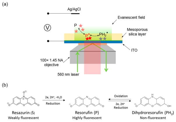
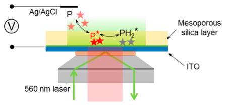
Inspired by Chen’s work and Bohn’s recent work on ZMW, we report the direct study of Faradaic processes of single freely diffusing redox molecules on an indium–tin oxide (ITO) electrode coated with mesoporous silica. In this work, we electrochemically deposited a high-quality thin film (<100 nm) of mesoporous silica on an ITO electrode to assist the study of single fluorogenic redox reactions with TIRF microscopy (Scheme 1a). The silica film had parallel nanochannels of ~3 nm in diameter vertically aligned on the electrode surface, allowing access of small redox molecules to the electrode.29–31 Restricted diffusional motion of resorufin molecules in mesoporous structures enabled us to resolve single redox molecules in the vicinity of the electrode surface and image tens of molecules simultaneously in the field of view. The adsorption and desorption behaviors of resorufin in mesoporous substrate were first characterized by analyzing single-molecule trajectories. Single-molecule electrochemistry of resorufin reduction to dihydraresorufin was then carried out on a silica-modified ITO electrode, and the electrochemical process was shown to follow an adsorption control.
Scheme 1. (a) Schematic Illustration of Single-Molecule Electrochemistry on a Porous Silica-Modified ITO Electrodea and (b) Reaction Scheme for Irreversible Reduction from Resazurin (S) to Resorufin (P), and Reversible Redox Reaction between Resorufin (P) and Dihydroresorufin (PH2).
aNot drawn to scale.
Compared to previous work, the use of electrochemically grown silica nanochannels allows study of freely diffusing single redox molecules in more highly confined solution volumes down to 0.7 zL (volume of a 3 nm diameter, 100 nm long channel). Because silica nanochannels can be grown on other conductive substrates, this method can be a general scheme for electrode modification for future studies of single redox events. Additionally, since the insulating silica walls can be readily modified with silane chemistry, one can introduce functional groups on the channel walls and build useful sensors with single-molecule sensitivity. More importantly, the ability to obtain and transfer freestanding mesoporous silica films onto other surfaces32 will enables one to develop a generalized method to study spatial heterogeneity in electrocatalytic activity of electrode surfaces with single-molecule sensitivity and sub-diffraction spatial resolution.
EXPERIMENTAL SECTION
Chemicals and Materials
Resorufin sodium salt (Invitrogen, 99%), resazurin sodium salt (Invitrogen, 99%), potassium chloride (KCl, J.T. Baker, 99.5%), monosodium phosphate monohydrate (NaH2PO4·H2O, J.T. Baker, 99%), disodium phosphate heptahydrate (Na2HPO4·7H2O, J.T. Baker, 98%), sodium nitrite (NaNOFF, Sigma, 99%), glucose (Sigma, 99.5%), sodium hydroxide (NaOH, J.T. Baker, 98.5%), hexaammineruthenium(III) chloride ([Ru(NH3)6]Cl3, Sigma-Aldrich, 98%), tetraethoxysilane (TEOS, Sigma, 99%), cetyltrimethylammonium bromide (CTAB, Sigma, 99%), ethanol (Decon Laboratories, 200 proof), hydrochloric acid (HCl, Macron, 37%), 3-aminopropyltriethoxysilane (APTES, Sigma, 98%), acetonitrile (Fisher Chemical, 99.9%), toluene (Fisher Chemical, 99.9%), methanol (Fisher Chemical, 99.9%), and poly(methyl methacrylate) (PMMA, Mw ≈ 996 000, Aldrich) were all used without further purification. Deionized water (>18 MΩ·cm) was obtained through a Barnstead Nanopure water purification system and used for all aqueous solutions.
Preparation of the Mesoporous Silica Films
A thin layer of mesoporous silica film was electrochemically deposited onto the ITO (SPI Supplies, surface resistivity 15–30 Ω) sputter-coated coverslips by the EASA method, as reported previously.30,31 Typically, a 20 mL aqueous solution of 0.1 M NaNOFF was first mixed with 20 mL of ethanol, followed by addition of HCl to adjust the pH close to 3. Next, 5 mmol of TEOS and 1.6 mmol of CTAB were added to the solution and stirred for 2.5 h. Before deposition, the ITO coverslip was sequentially cleaned by ultrasonication in deionized water and ethanol for 15 min and dried under a pure nitrogen flow. The cleaned ITO coverslip was used as the working electrode (WE) and immersed into the sol–gel solution. A Pt foil served as the counter electrode (CE) was disposed parallel to WE with 1 mm separation. A −1.1 V voltage was applied for 20 s with respect to an Ag/AgCl reference electrode (RE) by a potentiostat (CV-27 voltammograph). The mesoporous silica-coated ITO (silica-ITO) coverslip was quickly removed from the sol–gel solution, rinsed with deionized water. After drying and further aging in an oven at 130 °C overnight, the surfactant was removed by immersing the silica-ITO coverslip in an ethanol solution with 0.1 M HCl for 5 min. Finally, the silica-ITO coverslip was immersed into a 1% (v/v) APTES solution in acetonitrile for 20 min to modify the mesoporous silica layer with amino groups.
Instruments
The surface height profiles were measured using a Bruker OM-DektakXT Profilometer. Scanning electron microscopy (SEM) images were obtained using a field-emission microscope (FEI XL830). Both the surface height measurements and SEM images were carried out on the mesoporous silica coated ITO coverslips. TEM images were obtained using a FEI Tecnai G2 F20 transmission electron microscope under 200 kV with a single-tilt sample holder. The mesoporous silica film was electrochemically deposited onto a carbon coated TEM grid (Ted Pella, Inc.). The deposition time was 10 s, while other deposition conditions were the same as on ITO electrodes.
Single-Molecule Fluorescence Microscopy
Single-molecule fluorescence experiments were performed on a home-built Nikon Eclipse Ti-U chassis configured for total internal reflection (TIR) fluorescence using a Nikon Plan APO 100× 1.45 NA objective and a 560 nm laser source (MPB Communications). With a typical 1.4 kW/cm2 excitation illumination, the fluorescence images were filtered with an ET605/70m-2p band-pass filter (Chroma Technology Co.), and acquired on an EMCCD (iXon Ultra 897, Andor) operating at 10 frames per second. The voltage function was generated by a potentiostat (CV-27 Voltammograph) and applied on the silica-ITO working electrode with respect to an Ag/AgCl reference electrode (RE). A PCI-6251 (National Instruments) data acquisition card and a BNC-2090 breakup box were used to interface the potentiostat and the PC and to digitize the current–voltage signal.
Image Analysis
Single-molecule fluorescence images were analyzed using ThunderSTORM33 plug-in in ImageJ. Each fluorescent single molecular spot is described by a point spread function (PSF), which is fitted with a two-dimensional (2-D) Gaussian function to localize the center position. In order to determine the residence time of each single molecule, for every identified fluorescent molecule in a frame, the subsequent frames were searched for the molecules centered within the same pixel position, until no molecule was found within that pixel. Therefore, the entire residence time (τon) of each fluorophore was determined. τon represents the time of a single burst lasts in the fluorescence trajectory, and its distribution was further used to study the kinetics of adsorption/desorption and redox processes. The concentration of fluorophore is carefully controlled that the probability of two (or multiple) fluorescent molecules identified within the same pixel on one frame is less than 1% (e.g., 187 out of 21 130 fluorescent spots). The photon counts of each fluorescent burst on one frame were converted from the total integrated fluorescence signal counts under the fitted 2-D Gaussian function using ThunderSTORM.
RESULTS AND DISCUSSION
Electrochemical and Fluorescent Property of Resazurin, Resorufin, and Dihydroresorufin
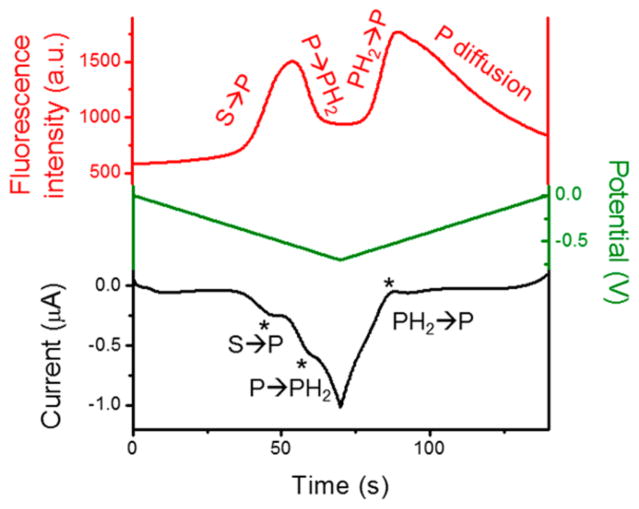
We first studied the electrochemical and fluorescence behaviors of resazurin, resorufin, and dihydroresorufin molecules (Scheme 1b) by recording both electrochemical and fluorescence signals in bulk and the results are shown in Figure 1. To obtain a well-defined voltammetric response, a 20 nm thick carbon film electrode (deposited on glass) and a high concentration of resazurin (50 μM) were selected. As shown in Figure 1, resazurin (S) was first reduced to resorufin (P), and resorufin further underwent another two-electron reduction process to form dihydroresorufin (PH2). 25,34 Three waves were observed in the voltammogram, corresponding to the irreversible S → P and reversible P ⇌ PH2 processes with the formal potentials of approximately −0.47 and −0.56 V (vs Ag/AgCl), respectively (Figure 1, black curve).9,35 The on–off responses of fluorescence intensity during the potential scan matched quite well with the positions of the current peaks, validating the electrochemical reduction and oxidation among the weakly fluorescent resazurin, highly fluorescent resorufin, and nonfluorescent dihydroresorufin (Figure 1, red curve).
Figure 1.
Fluorescence intensity (red) and current response (black) over the course of potential sweeping (green) from 0 to −0.7 V at the scan rate of 50 mV/s in 50 mM phosphate buffer (pH 7.4) containing 50 μM resazurin. WE, carbon film electrode (20 nm thick, deposited on a glass slide); RE, Ag/AgCl wire; CE, Pt wire.
During the continuous potential sweeps (Figure S1), the irreversible S P process resulted in an obvious OFF → ON fluorescence peak on the forward scan at the first potential cycle. However, the P molecule cannot be oxidized back to S on the reverse scan, resulting in a raised fluorescence background after each potential cycle. The total amount of S molecules available for the electrode was also rapidly consumed by the irreversible S → P process. Therefore, the fluorescence peak of S P completely disappeared at the third cycle (Figure S1, blue curve). The P ⇌ PH2 process corresponded to a reversible ON ⇌ OFF fluorescence switch during the multiple potential cycles. Especially when the resorufin was used as the starting reagent, this ON ⇌ OFF switch is found to be more distinct and reversible (Figure S1, red curve). This observation indicated the P ⇌ PH2 process is a more appropriate fluorogenic reaction for the single-molecule spectroelectro-chemical study. Therefore, the reversible P ⇌ PH2 process (Scheme 1b) was chosen as the model system for this work. Note that the electrode potentials on the ITO electrode measured here are slightly different from the potentials on the carbon film electrode (Figure 1), which is likely due to different electrocatalytic activities of the two electrode materials.
We were unable to resolve single resorufin molecules with TIRF microscopy on bare ITO electrodes. Despite a decreasing total fluorescence intensity observed as the concentration of resorufin was reduced to the nanomolar regime, no single-molecule fluorescence signal was resolvable on the bare ITO surface (Figure S2). This is likely due to a short residence time of resorufin (and insufficient number of photons collectable) in the interfacial region above the ITO surface. As described in the Introduction, the average time that a freely diffusing resorufin molecule may spend within the TIR excitation region (~200 nm above the ITO surface) can be estimated to be ~80 μs. An electron-multiplying CCD (EMCCD) camera running at full speed of 33 frames/second takes ~30 ms to acquire an image. Therefore, the estimated time t is too short for the camera to collect enough photons to resolve single molecules.36
We then spin-coated 1 nM resorufin solution in 2.5 mg/mL PMMA in toluene on glass and ITO substrates. The uniformly distributed single resorufin molecules were easily observed on both glass and ITO substrates. Although the interfacial electron transfer has been observed between the excited fluorophore and oxide semiconductor (e.g., ITO, SnO2, TiO2), 37–39 and the fluorescence intensities of the molecules on the semiconductor surface were reported to be weaker than those on the glass surface due to the lower emission quantum yield,37 our observations indicated that the single-molecule fluorescence imaging can still be readily carried out under the current conditions when the fluorophores are well immobilized on the surface.
Single-Molecule Imaging on a Mesoporous Silica-Coated ITO Electrode
In order to reduce the diffusional motion of resorufin within the TIR excitation region, a thin layer of mesoporous silica film was introduced. Typically, a thin mesoporous silica film is electrochemically deposited onto an ITO substrate by the EASA method.30,31 The EASA method allows one to deposit uniform silica films on an ITO electrode with excellent control over nanopore size, length, and uniformity. Although many spin-coated thin polymer films commonly used to immobilize the single dye molecules40 may block the faradaic current of the electrochemical process, the CTAB-templated thin mesoporous silica film with ~3 nm average size pores is permeable for small redox molecules.31 In addition, the silica film itself has nearly zero fluorescence background (Figure S3) making it an ideal substrate for imaging single molecules.
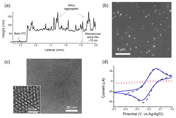
From the surface height profile in Figure 2a, the thickness of the deposited silica film is ~70 nm. The byproducts of a few particulate aggregates (100–200 nm in diameter) were also observed to be randomly distributed on the top surface of the uniform mesoporous silica film from both surface height profile and the SEM images (Figure 2a,b). TEM images revealed a hexagonal packing of the mesopores (Figure 2c), and the repeat spacing of the porous structures is around 3.5–4 nm (Figure 2c, inset). Right after the deposition of mesoporous silica film on the ITO coverslip, the electrochemical measurements showed significantly suppressed electrochemical current from Ru(NH3)63+ (Figure 2d, red dotted trace), compared to the bare ITO electrode (Figure 2d, black dashed trace). The mesopore channels were filled with CATB surfactants, which blocked the solution-phase redox probe Ru(NH3)63+ reaching to the electrode. After the removal of surfactant using ethanol/HCl solution, the Ru(NH3)63+ redox molecules are free to diffuse across the mesopore channels to the underlying electrode, and thus the electrochemical current recovered (Figure 2d, blue solid trace). Considering the negative charges on the silica surfaces and the resorufin molecules at neutral pH, the mesoporous silica layer was further modified with amino groups to balance its negative charges, and a high concentration electrolyte (1 M KCl) was used to further screen the charges of the silica film in the single-molecule spectroelectrochemical studies.
Figure 2.
(a) Surface height profile of a thin mesoporous silica film on the ITO surface. (b) SEM image of mesoporous silica film on the ITO surface. (c) TEM image of mesoporous silica film (top view) deposited on a carbon-coated TEM grid. Inset: high-magnification top view. (d) CVs of 1 mM Ru(NH3)63+ in 1 M KCl on the bare ITO (black dashed) and the mesoporous silica-ITO electrode before (red dotted) and after (blue solid) the removal of surfactant templates. Scan rate: 50 mV/s.
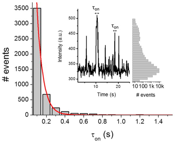
In the presence of the mesoporous silica film, single resorufin molecules can be easily observed on the ITO electrode (Figure S4a). The single molecular bright spots were further identified and localized by two-dimensional (2-D) Gaussian fitting using an ImageJ plug-in ThunderSTORM33 (Figures S4b and S5). When a single fluorescent molecule was temporarily trapped or adsorbed on the mesoporous silica film, a burst of fluorescence trajectory was immediately observed (Figure 3, inset). This process is highly random and reversible on the silica-ITO surfaces as judged from the fluorescence images.
Figure 3.
Distribution of τon of single resorufin molecules on the mesoporous silica coated ITO surface. Red line is a single-exponential decay fit with a time constant of 0.064 ± 0.003 s. Inset: (left) the fluorescence trajectory from one fluorescent spot; (right) histogram of the fluorescence trajectory over a 13 × 13 μm2 area for 40 s.
With the help of the mesoporous silica film, we were able to carry out kinetic measurements on the adsorption and desorption processes of resorufin on an ITO electrode. The residence time (τon) is the time of a single burst lasts in the fluorescence trajectory. It represents the time that single resorufin molecule stays on the silica-ITO surface before been turned off, which may include three possible pathways: photobleaching, blinking or dissociation from the silica-ITO surface. As shown in Figure 3, the distribution of τon of resorufin molecules on the silica-ITO surface follows a single-exponential decay with a time constant of 0.064 ± 0.003 s. This value is smaller than the time constant of photobleaching lifetime (8.78 ± 2.97 s) or blinking on-time (0.74 ± 0.03 s) of resorufin under the same excitation laser power density (Figure S6). The τon of resourfin molecules is also independent of the laser power density (Figure S7). Thus, photobleaching and blinking are less likely to contribute significantly to the single-molecule fluorescence trajectories, and the dissociation from the silica-ITO surface is the main pathway that turns fluorescent resorufin molecule into the “off-state”. Therefore, τon carries the information about dissociation kinetics of single resorufin molecules on the mesoporous silica film. Considering the following process: resorufin molecule, P, diffusing freely in the bulk solution, temporarily and reversibly adsorbed on the mesoporous silica film, becoming a temporarily trapped resorufin, P*, which is captured by the camera,
| (1) |
where k1 and k−1 are the rate constants of adsorption and desorption, respectively. τon measures the residence time of P* on the surface, which follows a single-exponential decay with a time constant of τon = (k−1)−1.41
At equilibrium, more single molecular spots were observed as the resorufin concentration was increased to 10 nM (Figure S8). From the results with the resorufin concentration ranging from 10 pM to 1 nM, the equilibrium constant K = k1/k−1 = [P*]/[P] = 6.36 × 1015 cm−2 M−1 = 0.11 μm was calculated. Consequently, the desorption and adsorption rate constants were determined to be k−1 = (τon)−1 = 15.71 ± 0.76 s−1, and k1 = Kk−1 = (1.73 ± 0.08) × 10−4 cm·s−1. The large k−1 value indicates a very fast desorption kinetics of resorufin molecule on the mesoporous silica coating layer. The kinetics results have confirmed that resorufin molecules can diffuse in and out of mesoporous silica membrane with hindered diffusion. The average residence time is nearly 3 orders magnitude greater than that on bare ITO. As such, we can carry out further electrochemical studies of single molecules.
Electrochemical Reduction of Single Resorufin Molecules
We used single-molecule TIRF microscopy to monitor the total population of fluorescent resorufin molecules as the electrode potential was changed. The number of resorufin molecules decreases upon reduction to dihydroresorufin on the electrode. Assuming the total number of redox molecules (P + PH2) is constant at a given time and potential, the normalized number of the fluorescent P molecules observed would represent the probability of the molecule being in the oxidized state, which is predictable from the Nernst equation:
| (2) |
where E is the applied potential on the ITO electrode, E0′ is the formal potential of the redox reaction, R is the gas constant, T is the absolute temperature, n is the number of electrons transferred in the redox reaction, F is the Faraday’s constant, [P] and [PH2] are the redox concentrations at the electrode surface. One can see from the Nernst equation that as the electrode potential is higher than the formal potential, most of the redox molecules would stay in the oxidized form as resorufin in this case. On the other hand, as the electrode potential is decreased, more molecules would be transferred to PH2 losing their fluorescence. For a single redox molecule, the probability of finding the molecule sitting in the oxidized form is thus dependent on the applied electrode potential in a same way as described by eq 2. As such, the probability of observing fluorescent P molecules in the image in this study would be strongly dependent on the applied potential on the electrode.
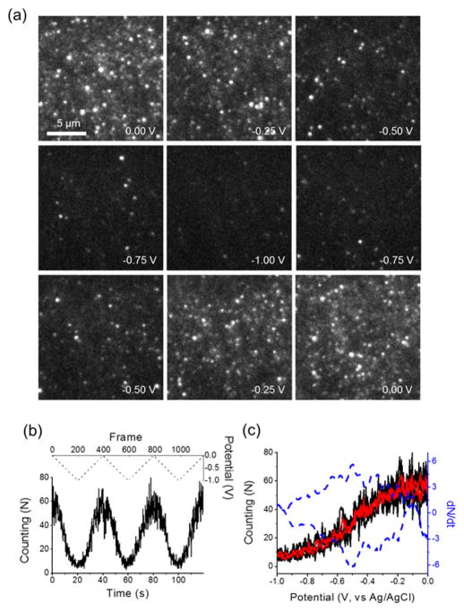
Here, a triangular potential waveform from 0 to −1 V at 50 mV/s was applied on the silica-ITO electrode in 1 nM resorufin solution. The potential dependent surface population of resorufin molecules is shown in Figure 4a. The population of resorufin molecules decreases drastically as the potential drops to −1 V, and recovers back to its original value when the potential scans back to 0 V, as expected. This fully reversible potential response is due to the electrochemical reduction of resorufin to its non-fluorescence form, dihydroresorufin, which is then oxidized back to resorufin at higher potentials. From the fluorescence images (Figure 4a), the single molecular spots on each frame were identified and counted. The counting results were strongly correlated to the applied potentials in three continuous cyclic voltammetry (CV) scans (Figure 4b,c, black trace).
Figure 4.
(a) A series of fluorescence images captured over the potential sweep of 1 nM resorufin in 50 mM phosphate buffer (pH 7.4) and 1 M KCl solution on the silica-ITO electrode. The potential was cycled from 0 to −1 V versus an Ag/AgCl reference electrode at the scan of 50 mV/s. Image size is 16 μm × 16 μm. (b) The number of single molecular spots detected on each frame over three continuous potential sweeps (black solid). The potential waveform was shown in dashed line. (c) The plot of the number of single molecular spots detected on each frame (black) and averaged over three potential sweeps (red), and the time derivative (blue dashed) as a function of applied potential from 0 to −1 V.
From the images in Figure 4a, it is interesting to notice that not all the fluorescent molecules were turned off even when the electrode potential was decreased to −1 V. The residual few resorufin molecules may be held away from the ITO electrode surface by temporally adsorbing either on the sidewalls of the mesopore channels or the top surface of the mesoporous layer. These molecules may also be trapped in locations where the electrochemical reduction was not favorable due to heterogeneity on the ITO surfaces. These molecules were still within the TIR excitation region, but were not effectively reduced on the underlying electrode.
For a given electrode area, the variations of detected number (N) of single molecules on each frame indicate the surface coverage of resorufin molecule ([P*]). Considering the reversible adsorption/desorption process on the silica-ITO surface, and the weakly fluorescent, overlapped or diffusive resorufin molecules that are not identified by ThunderSTORM, the detected number (N) is only a fraction of the total number of molecules (γN) which have been trapped by the mesoporous silica film. Therefore, the observed surface coverage change (ΔNi = NEi – NE0) at certain applied potential is proportional to the amount of resorufin molecules being reduced (γΔNi). For a two-electron redox process, the total charge passed through the electrode can be expressed as Q = 2γFΔNi. As such, the time derivative of the detected number (dN/dt) measures the faradaic current associated with the redox process (P ⇌ PH2),
Therefore, the plot of dN/dt versus applied potential should be linearly correlated to the current signal in the cyclic voltammogram. Two peaks, [dN/dt]p, were observed on the forward and reverse scans (Figure 4c, blue dashed curve). Note that the average counting results over three continuous CV scans (Figure 4c, red trace) were used to calculate the time derivative (dN/dt) with reduced noise level.
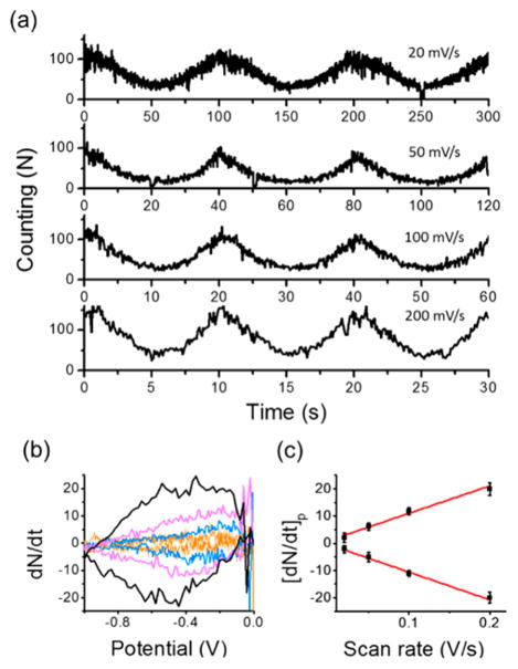
For the reversible one-step redox process (P ⇌ PH2), the detected number of single molecules showed similar voltage responses at four distinct scan rates (Figure 5a). The time derivative results showed higher dN/dt values at faster scan rates (Figure 5b), and the peak values[dN/dt]p were found to be proportional to the scan rate (ν), which implies a surface-controlled electrochemical kinetics (Figures 5c and S9). For a comparison, the ensemble behavior of the same redox reaction of P ⇌ PH2 was also measured at different scan rates on the bare ITO electrode. The fluorescence intensity, rather than the number of single molecule, was recorded. Without the thin mesoporous silica film, the relationship between the time derivative of the fluorescence intensity and the scan rate was found to follow a diffusion-controlled electrochemical kinetics (Figure S10). In addition, the potential dependent surface population with resorufin solution concentration ranging from 10 pM to 10 nM was also studied. The peak values of the time derivative results, [dN/dt]p, were proportional to the fluorophore concentrations lower than 1 nM (Figure S11).
Figure 5.
(a) The number of single molecular spots detected on each frame over three continuous potential sweeps with the scan rate of 20 mV/s, 50 mV/s, 100 mV/s, and 200 mV/s in 1 nM resorufin solution containing 50 mM phosphate buffer (pH 7.4) and 1 M KCl on the silica-ITO electrode. (b) The time derivative of the number of single molecular spots as a function of applied potential from 0 to −1 V at different scan rates of 20 mV/s (orange), 50 mV/s (blue), 100 mV/s (magenta), and 200 mV/s (black). (c) The scan rate dependence of the peak values (black square) of the time derivative traces in (b). Red lines are the linear fit.
The process of single resorufin molecule adsorption/desorption and reversible reduction to the off-state dihydroresorufin on the silica-ITO surface can be described by a three-state kinetic model,
| (3) |
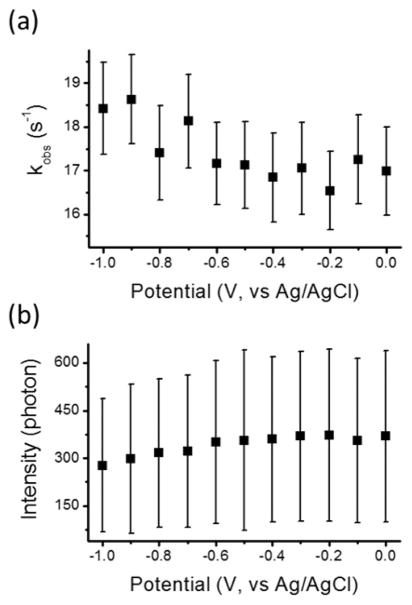
where kred and kox are the rate constants of resorufin reduction and dihydroresorufin oxidation, respectively; asterisk indicates the molecules adsorbed on the silica-ITO surface. In this model, only P* is imaged, and the residence time (τon) histogram follows a biexponential decay model.41,42 Therefore, when the potential decreased from 0 to −1 V, the process on the silica-ITO surface transformed from two-state kinetic model (1) to three-state kinetic model (3), and the τon distributions were also expected to undergo a transition from single-exponential to biexponential decay. However, we compared the τon distributions at the potentials from 0 to −1 V with 0.1 V step, and found all the distributions can be fitted by the single-exponential decay model with similar residuals (Figure S12). It is attributed to the large desorption rate constant (k−1) that the τon values of the majority of single resorufin molecules do not span enough frames to further resolve the kinetics of the redox process (P ⇌ PH2). Nevertheless, the time constant (kobs−1) of the single-exponential decay (Figure S12a) still measures the kinetics (kobs) of the mechanisms that turn off the single resorufin molecules, including two parallel k−1 and kred pathways. With the potential dropping from 0 to −1 V, the kobs value increases (Figure 6a). Assuming k1 and k−1 are independent of the external applied potentials, this observation implies a higher contribution of kred at lower potentials, which is consistent with its electrochemical reduction reaction.
Figure 6.
(a) Measured kobs, the time constant of single-exponential decay of τon distribution, and (b) the average number of photons per fluorescent spot at the potentials from 0 to −1 V with 0.1 V step. The error bars indicate the standard deviation.
Since the measured turn-off rate (kobs) is faster than the camera speed (10 s−1), most of the recognized fluorescent spots only lasted one frame (Figure 3, the bin of τon = 0.1 s), and were further turned off (k−1 or kred pathways) within one exposure period. At more negative potentials, resorufin molecules are reduced to dihydroresorufin (kred), and the on-period of each fluorescent molecule is more likely to be shorter than one exposure period, resulting in a lower number of accumulated photons per fluorescent spot in one image. As shown in Figure 6b, the accumulated photons per fluorescent spot were decreasing as the potential scanning from 0 to −1 V.
CONCLUSIONS
In summary, we have demonstrated single-molecule electro-chemistry of resorufin on a transparent ITO electrode with the assistance of a thin film of mesoporous silica. The key in this study was the use of electrodeposited mesoporous silica which reduced the rate of diffusion of fluorogenic redox molecules enabling real-time imaging of single redox events with TIRF. The adsorption and desorption kinetic mechanisms of single resorufin molecule on the mesoporous film were studied from temporal fluctuations of the single-molecule trajectories and the corresponding rate constants were determined. The reversible redox process between the highly fluorescent resorufin and non-fluorescent dihydroresorufin was studied by analyzing the potential dependent surface population of resorufin molecules. Our results confirmed that resorufin reduction to dihydroresorufin is a surface adsorption-controlled electrochemical process when the ITO surface is covered by porous silica. The kinetic mechanism of the redox process on the mesoporous film was proposed and the potential dependent reduction rate constants and single-molecule intensities were also discussed.
Due to a very fast desorption kinetics of resorufin molecules on the mesoporous silica film, we were unable to directly determine the kinetics of the redox process from the fluorescence trajectories. Our ongoing studies focus on fine-tuning the properties of the mesoporous silica film including film thickness, pore size, and surface chemistry,30,43 in order to further improve its performance in single-molecule electro-chemistry. The future incorporation this method with FEEM also holds the possibility for optically reporting single electron-transfer process of any electroactive species.
Supplementary Material
Acknowledgments
We gratefully acknowledge financial support from National Science Foundation (grant CHE-1515897 to B.Z., and NSF Graduate Research Fellowship to M.D.H. under Grant DGE-1256082), the National Institutes of Health (GM101133 to B.Z.), the University of Washington (J.C.V.), and a Burroughs Wellcome Fund Career Award at the Scientific Interface (J.C.V.). We also thank Professor Joel M. Harris of University of Utah for helpful discussions. Part of this work was conducted at the University of Washington NanoTech User Facility, a member of the National Science Foundation, National Nanotechnology Infrastructure Network (NNIN) and the Washington Technology Center (WTC).
Footnotes
The authors declare no competing financial interest.
The Supporting Information is available free of charge on the ACS Publications website at DOI: 10.1021/jacs.6b10191.
Figures S1–S12, with additional information as noted in the text (PDF)
References
- 1.Bard AJ, Faulkner LR. Electrochemical Methods: Fundamentals and Applications. 2. John Wiley; New York: 2001. [Google Scholar]
- 2.Fan FR, Bard AJ. Science. 1995;267:871–874. doi: 10.1126/science.267.5199.871. [DOI] [PubMed] [Google Scholar]
- 3.Sun P, Mirkin MV. J Am Chem Soc. 2008;130:8241–8250. doi: 10.1021/ja711088j. [DOI] [PubMed] [Google Scholar]
- 4.Zevenbergen MA, Singh PS, Goluch ED, Wolfrum BL, Lemay SG. Nano Lett. 2011;11:2881–2886. doi: 10.1021/nl2013423. [DOI] [PubMed] [Google Scholar]
- 5.Kang S, Nieuwenhuis A, Mathwig K, Mampallil D, Lemay SG. ACS Nano. 2013;7:10931–10937. doi: 10.1021/nn404440v. [DOI] [PubMed] [Google Scholar]
- 6.Collinson MM, Wightman RM. Science. 1995;268:1883–1885. doi: 10.1126/science.268.5219.1883. [DOI] [PubMed] [Google Scholar]
- 7.Palacios RE, Fan FR, Bard AJ, Barbara PF. J Am Chem Soc. 2006;128:9028–9029. doi: 10.1021/ja062848e. [DOI] [PubMed] [Google Scholar]
- 8.Akkilic N, Kamran M, Stan R, Sanghamitra NJM. Biosens Bioelectron. 2015;67:747–751. doi: 10.1016/j.bios.2014.07.051. [DOI] [PubMed] [Google Scholar]
- 9.Xu W, Shen H, Kim YJ, Zhou X, Liu G, Park J, Chen P. Nano Lett. 2009;9:3968–3973. doi: 10.1021/nl900988f. [DOI] [PubMed] [Google Scholar]
- 10.Chang YL, Palacios RE, Fan FR, Bard AJ, Barbara PF. J Am Chem Soc. 2008;130:8906–8907. doi: 10.1021/ja803454x. [DOI] [PubMed] [Google Scholar]
- 11.Lei C, Hu D, Ackerman EJ. Chem Commun. 2008:5490–5492. doi: 10.1039/b812161c. [DOI] [PubMed] [Google Scholar]
- 12.Liu J, Hill CM, Pan S, Liu H. Phys Chem Chem Phys. 2014;16:23150–23156. doi: 10.1039/c4cp02950j. [DOI] [PubMed] [Google Scholar]
- 13.Zhao J, Zaino LP, III, Bohn PW. Faraday Discuss. 2013;164:57–69. doi: 10.1039/c3fd00013c. [DOI] [PubMed] [Google Scholar]
- 14.Cortes E, Etchegoin PG, Le Ru EC, Fainstein A, Vela ME, Salvarezza RC. J Am Chem Soc. 2010;132:18034–18037. doi: 10.1021/ja108989b. [DOI] [PubMed] [Google Scholar]
- 15.Zaleski S, Cardinal MF, Klingsporn JM, Van Duyne RP. J Phys Chem C. 2015;119:28226–28234. [Google Scholar]
- 16.Mathwig K, Aartsma TJ, Canters GW, Lemay SG. Annu Rev Anal Chem. 2014;7:383–404. doi: 10.1146/annurev-anchem-062012-092557. [DOI] [PubMed] [Google Scholar]
- 17.Zaino LP, III, Grismer DA, Han D, Crouch GM, Bohn PW. Faraday Discuss. 2015;184:101–115. doi: 10.1039/c5fd00072f. [DOI] [PubMed] [Google Scholar]
- 18.Funatsu T, Harada Y, Tokunaga M, Saito K, Yanagida T. Nature. 1995;374:555–559. doi: 10.1038/374555a0. [DOI] [PubMed] [Google Scholar]
- 19.Schneckenburger H. Curr Opin Biotechnol. 2005;16:13–18. doi: 10.1016/j.copbio.2004.12.004. [DOI] [PubMed] [Google Scholar]
- 20.Hess ST, Girirajan TPK, Mason MD. Biophys J. 2006;91:4258–4272. doi: 10.1529/biophysj.106.091116. [DOI] [PMC free article] [PubMed] [Google Scholar]
- 21.Bates M, Huang B, Zhuang X. Curr Opin Chem Biol. 2008;12:505–514. doi: 10.1016/j.cbpa.2008.08.008. [DOI] [PMC free article] [PubMed] [Google Scholar]
- 22.Rust MJ, Bates M, Zhuang XW. Nat Methods. 2006;3:793–795. doi: 10.1038/nmeth929. [DOI] [PMC free article] [PubMed] [Google Scholar]
- 23.Betzig E, Patterson GH, Sougrat R, Lindwasser OW, Olenych S, Bonifacino JS, Davidson MW, Lippincott-Schwartz J, Hess HF. Science. 2006;313:1642–1645. doi: 10.1126/science.1127344. [DOI] [PubMed] [Google Scholar]
- 24.Guerrette JP, Percival SJ, Zhang B. J Am Chem Soc. 2013;135:855–861. doi: 10.1021/ja310401b. [DOI] [PubMed] [Google Scholar]
- 25.Oja SM, Guerrette JP, David MR, Zhang B. Anal Chem. 2014;86:6040–6048. doi: 10.1021/ac501194j. [DOI] [PMC free article] [PubMed] [Google Scholar]
- 26.Oja SM, Zhang B. Anal Chem. 2014;86:12299–12307. doi: 10.1021/ac5035715. [DOI] [PubMed] [Google Scholar]
- 27.Andoy NM, Zhou X, Choudhary E, Shen H, Liu G, Chen P. J Am Chem Soc. 2013;135:1845–1852. doi: 10.1021/ja309948y. [DOI] [PubMed] [Google Scholar]
- 28.Zhou X, Andoy NM, Liu G, Choudhary E, Han KS, Shen H, Chen P. Nat Nanotechnol. 2012;7:237–241. doi: 10.1038/nnano.2012.18. [DOI] [PubMed] [Google Scholar]
- 29.Davis ME. Nature. 2002;417:813–821. doi: 10.1038/nature00785. [DOI] [PubMed] [Google Scholar]
- 30.Goux A, Etienne M, Aubert E, Lecomte C, Ghanbaja J, Walcarius A. Chem Mater. 2009;21:731–741. [Google Scholar]
- 31.Walcarius A, Sibottier E, Etienne M, Ghanbaja J. Nat Mater. 2007;6:602–608. doi: 10.1038/nmat1951. [DOI] [PubMed] [Google Scholar]
- 32.Lin X, Yang Q, Ding L, Su B. ACS Nano. 2015;9:11266–11277. doi: 10.1021/acsnano.5b04887. [DOI] [PubMed] [Google Scholar]
- 33.Ovesny M, Krizek P, Borkovec J, Svindrych Z, Hagen GM. Bioinformatics. 2014;30:2389–2390. doi: 10.1093/bioinformatics/btu202. [DOI] [PMC free article] [PubMed] [Google Scholar]
- 34.Twigg RS. Nature. 1945;155:401–402. [Google Scholar]
- 35.Khazalpour S, Nematollahi D. RSC Adv. 2014;4:8431–8438. [Google Scholar]
- 36.Xu W, Kong JS, Yeh YT, Chen P. Nat Mater. 2008;7:992–996. doi: 10.1038/nmat2319. [DOI] [PubMed] [Google Scholar]
- 37.Lu HP, Xie XS. J Phys Chem B. 1997;101:2753–2757. [Google Scholar]
- 38.Liu D, Kamat PV. J Chem Phys. 1996;105:965–970. [Google Scholar]
- 39.Rao VG, Dhital B, Lu HP. Chem Commun. 2015;51:16821–16824. doi: 10.1039/c5cc06451a. [DOI] [PubMed] [Google Scholar]
- 40.Zheng D, Kaldaras L, Lu HP. Rev Sci Instrum. 2012;83:013110. doi: 10.1063/1.3677334. [DOI] [PMC free article] [PubMed] [Google Scholar]
- 41.Myers GA, Gacek DA, Peterson EM, Fox CB, Harris JM. J Am Chem Soc. 2012;134:19652–19660. doi: 10.1021/ja306074k. [DOI] [PubMed] [Google Scholar]
- 42.Capellos C, Bielski BHJ. Kinetic systems: Mathematical description of chemical kinetics in solution. Wiley-Interscience; New York: 1972. p. 35. [Google Scholar]
- 43.Vila N, Ghanbaja J, Aubert E, Walcarius A. Angew Chem, Int Ed. 2014;53:2945–2950. doi: 10.1002/anie.201309447. [DOI] [PubMed] [Google Scholar]
Associated Data
This section collects any data citations, data availability statements, or supplementary materials included in this article.


