Abstract
The electrocardiogram (ECG) signal can be derived from different sources. These include systems for surface ECG, Holter monitoring, ergometric stress tests, and telemetry systems and bedside monitoring of vital parameters, which are useful for rhythm and ST-segment analysis and ECG screening of electrical sudden cardiac death predictors. A precise ECG diagnosis is based upon correct recording, elaboration, and presentation of the signal. Several sources of artefacts and potential external causes may influence the quality of the original ECG waveforms. Other factors that may affect the quality of the information presented depend upon the technical solutions employed to improve the signal. The choice of the instrumentations and solutions used to offer a high-quality ECG signal are, therefore, of paramount importance. Some requirements are reported in detail in scientific statements and recommendations. The aim of this consensus document is to give scientific reference for the choice of systems able to offer high quality ECG signal acquisition, processing, and presentation suitable for clinical use.
Keywords: ECG monitoring, ECG signals, Electrocardiogram, Ergometry, Holter ECG, Telemetry
Document Revisors: Roberto Cemin, Domenico Gabrielli, Marco Sicuro.
Consensus Document Approval Faculty in the Appendix
Table of contents
Introduction and aims of the document 394
Origin of the cardiac electric signal 394
Polarization of the myocardial cells 394
Depolarization of the myocardial cells and action potential 395
Formation and transmission of the signal 395
The propagation of the depolarization in a cardiac fiber 395
Cardiac dipole theory 396
Propagation of currents through the chest and the limbs 397
Intensity of the source 397
Capturing the electrocardiogram signal: processes and filtering 398
Factors that affect signal quality 399
Critical factors in morphology 400
The main technological solutions: interpretations and automatic medical recordings. Precision of the electrocardiogram signal analysis 402
Electrocardiogram automatic recording 402
Electrocardiogram automatic reporting 402
Fundamental recommendations for the acquisition of diagnostic devices 403
Electrocardiographs 403
Dynamic 24-28H electrocardiogram system according to Holter 403
Ergometries 403
Telemetries and monitoring 403
Artifacts and their control 403
How to perform an electrocardiogram correctly 403
Interferences due to alternating current 403
Muscle tremors 404
Instability of the isoelectric line 404
Bedside monitors 404
Ergometric tests 404
Dynamic Holter electrocardiogram 404
International standards, guidelines and norms in force 405
International standards 405
Guidelines 407
Norms in force 409
Transmission of the electrocardiogram signal from the local out-of-hospital/118/facilities 412
Transmission and reporting of out-of-hospital electrocardiogram signals and waveforms
Miscellaneous 413
Conclusions 413
Summary 414
Appendix 414
References 414
Introduction and aims of the document
Surface electrocardiogram (ECG) is the main and most common method used in cardiological examinations; the waveforms obtained represent the specific electrical activities of the heart chambers. At rest, the ECG photographs cardiac activity at the moment it is performed, whereas ECG monitoring is a continuous recording of the heart’s electrical activity.
The indispensable premise for a correct analysis of the ECG signal is to have good ECG waveforms at hand. The ECG signal today can be derived from a multitude of devices comprising electrocardiographs, Holter recording systems, bedside monitors, telemetries, and ergometry systems.
Along with these, so to say, conventional systems available for clinical usage, there are a variety of devices that derive data for the measuring, transmission, and archiving of ECG signals. The quality of the electrical signal is an important requisite that is generally acknowledged for any type of device capable of offering a waveform of the rhythm and morphology of the electrical activity of the heart. Indeed, there are important factors that require necessary quality for diagnostic purposes. The quality of the heart’s electrical signal for diagnostic purposes and the use of technical measures that guarantee the correct recording of those electrical phenomena are of fundamental importance in the analysis of the interpretation of the signal. If on the one hand, components without sufficient characteristics compared with the recommended requisites can result in cost saving and, consequently, in lower prices, on the other hand, they can concretely lead to altering the ECG signal; this may introduce artefacts, hide potentially useful information and, therefore, cover up the waveforms, thus causing possible erroneous or even hazardous behaviour. Furthermore, it is important to be familiar with the fundamental aspects concerning the quality of the signal and the techniques used in the various function modes in order to judge and assess the devices proposed for clinical use. The aim of this document is to present the essential features that can help to define the accuracy, precision, and suitability of the ECG signal. In addition, we shall deal with the most important aspects of the recommendations that may help clinicians who intend to equip themselves with ECG recording devices in various modes.
Origins of the cardiac electrical signal
Polarization of the myocardial cells
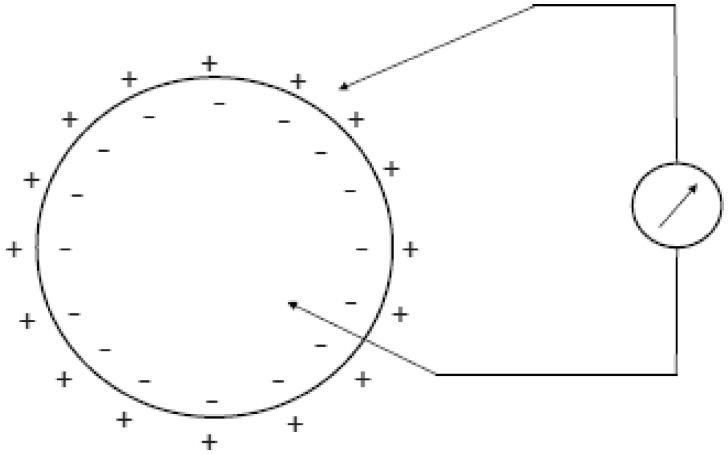
The mechanisms at the basis of the generation of cardiac electrical signals may be traced back to the processes of depolarization, diffusion, and repolarization of the myocardium’s cell membranes. The muscle cells, like the nervous cells that compose the heart tissue, are characterized by having their excitable cell membranes. The cell membrane is what separates the extracellular fluid from the intracellular fluid; these fluids have different ionic concentrations. The membrane in turn is characterized by a different permeability to the various ions. As a consequence of this diverse concentration, there is a difference in electrical potential between the outside and inside of the cell. The main ions involved in the potential generating mechanism are sodium (Na+), potassium (K+), and chlorine (Cl−). The different concentrations of ions are partly due to the different permeabilities of the membrane to the different ions, and the active mechanisms (the ionic pumps) that actively pump ions through the membrane, through the energy arising from the cell metabolism. In particular, in resting conditions, the sodium is expulsed from the cell, whereas the potassium is led to the inside. The balance between membrane permeability and activities of the ionic pumps determine an intracellular environment rich in potassium and poor in sodium, compared with an extracellular environment with high sodium concentrations and poor in potassium. In these conditions, a difference in electric potential is generated astride the cell membrane (polarization), with the interior of the cell at a potential of about 90 mV lower compared with the outside (Figure 1). In most of the cells, this potential remains constant until the cell is stimulated by a nervous cell or adjacent muscle cell, or in case of sensorial cells, by a thermal, mechanical, or chemical stimulus.
Figure 1.
The drawing schematically shows the difference in potential that comes about between the internal and external part of the myocardial cell membrane.
In some heart cells, the membrane potential tends to diminish spontaneously in time, and as we shall see below, this allows for a spontaneous rhythm which is at the base of the generation of the cardiac rhythm.
Depolarization of the myodcardial cells and action potential
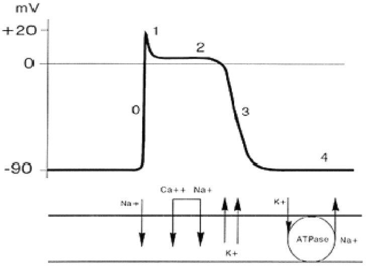
When a cell is stimulated, the permeability of the membrane changes at the passage of the ions. The first phase is characterized by an elevated permeability to sodium, which determines a significant entry of sodium ions inside the cell, with an increased potential inside the cell up to a value of about +20 mV (depolarization), the value at which a new equilibrium is reached between the flows of sodium and potassium. At this point, the membrane’s permeability to sodium returns to normality, whereas permeability to potassium greatly increases (about 30 times)by allowing the potassium to exit from the cell and bring back the membrane potential to the starting values. Lastly, the sodium/potassium pumps re-establish the initial ionic concentrations, and once the level is reached, the cell is again able to respond to a new stimulus (Figure 2). With time, the potential trend of the membrane during the depolarization and repolarization phases is indicated with the term of action potential. It is interesting to observe how the form and amplitude of the action potential for a given cell does not depend on the intensity of the stumulus, albeit the stimulus is enough to trigger the action potential (all or nothing response). Some cardiac cells are able to depolarize spontaneously even without external or adjacent cell stimuli. This particular type of cell is present in the sinoatrial node, the atrioventricular node and in the conduction tissue, with progressively greater depolarization times. In these cells, the membrane potential tends to slowly increase up to when a certain threshold is reached and beyond which depolarization is triggered. In a tissue, the depolarization of a cell is propagated to the adjacent cells until the entire tissue has not depolarized. In the myocardial tissue, electrical depolarization triggers the mechanical contraction. The activities of the cell membrane generate flows of ions through the membrane itself which in turn cause changes in the distribution of ions in the membrane’s external space. These ionic flows that pass within the chest determine changes of potential that spread up to the chest surface, where they can be measured through surface electrodes.
Figure 2.
Schematic drawing of the action potential and its underlying mechanisms.
Formation and transmission of the signal
As illustrated in the previous chapter, the cardiac electrical signal arises from depolarization and repolarization phenomena of the single myocardial cells. However, to understand how, from the behaviour of the single cells, one can reach the ECG signal measurable on the skin of the chest or the extremity of the limbs, we have to consider three fundamental aspects: the propagation mode of the depolarization in a muscle fibre, overall distribution of the electrical currents during the propagation, and the propagation of the currents through the chest and limbs up to the electrodes.
Propagation of depolarization in a cardiac fibre
Every myocardial fibre is formed by several single cells separated from the others by an intercalated disc. Resistance to the passage of an electrical current offered by the intercalated discs is very low (estimated at 1/400 compared with that of the external membrane of the myocardial fibres); the intercalated discs are a high electrical conductivity area that allows the propagation of a current density generated by an active cell in a nearby zone, allowing action potential to be propagated. The myocardium may be defined as a functional syncytium composed of numerous microcells interconnected with each other and able to transmit the action potential with great facility. Furthermore, at a macroscopic level, electrical continuity is interrupted between atriums and ventricles, which are separated by fibrous tissue. In normal conditions the action potentials pass from the atrial syncytium to the ventricular syncytium through a specialized conduction system called the atrioventricular bundle.
To understand the characteristics of the ECG signal, we need to start from the examination of the behaviour of a single myocardial fibre in which an action potential is propagated. This situation is shown in Figure 2 which schematically shows the single cells of a myocardial fibre, in the three typical phases of an action potential: resting, depolarization, and repolarization. If we consider a portion of a fibre, the cells of which are at one extreme in a resting condition (polarized) and the opposite cells are in the depolarization phase, in the extracellular volume we can see a concentration of positive ions in the zone of the cells at rest, and a concentration of negative ions in the zone of the depolarized cells (Figure 3). A potential difference gauge connected through two electrodes at the extremities of the fibre as shown in Figure 2, would show a positive deflection during the action potential propagation phase, while no electrical activity will be gauged before and after. During the cardiac cycle, therefore, there is an instantaneous distribution of potential on the surface of the myocardium, which is determined by the propagation of a wave through the myocardium: the first front of the wave is generated by the depolarization of the cardiac cells involved, wheras the 2nd is generated by their repolarization. The description of the behaviour of a single myocardial fibre during the propagation of an action potential gives us a first key to interpret the surface ECG signal: it describes the differences in potential induced on the body surface by the electrical currents that are generated by the formation and progression of a dual layer of electrical currents. Moreover, it is important to highlight how the gauging of the potential will be maximum, in cases where the propagation front moves in a direction parallel to the line that joins the two recording electrodes (this junction line is called a lead). Figure 4 describes the situation related to a single muscle fibre in which an action potential is propagating. The lead parallel to the propagation direction will allow the measurement of the maximum difference of potential, whereas the opposite lead placed perpendicularly to the propagation direction will not register an important differences in potential; more generally, therefore, couplets of electrodes (leads) set in different directions will supply different potential differences due to the different orientation with reference to the propagation direction of the action potential and the different distance from it (Figure 4). A further factor to bear in mind to understand how the ECG signal is generated, is that the distribution of currents during the propagation of action potential is of a dipolar type, with two groups of currents with opposite signals facing one another. Therefore, the propagation of an action potential along a myocardial fibre may be described through its origin, intensity, and direction (size of vector), and can be gauged through one or more leads. These elements are at the basis of the main theory used to comprehend the meaning of the ECG waves that can be measured on the skin of the body: the cardiac electric dipole theory.
Figure 3.

Sequence of events recorded outside the myocardial functional syncytium during the cardiac cycle and relative differences in potential measurable from a potential difference meter.
Figure 4.
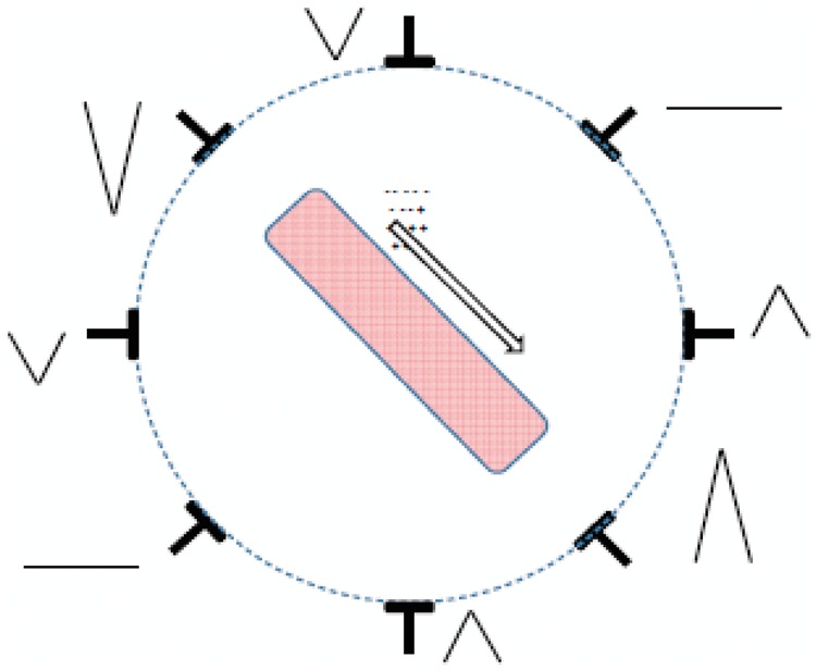
Registration of the difference in potential that can be derived from more observation points of a single muscle fiber in which an action potential is propagating.
The cardiac dipole theory
The phenomenon of the propagation of the action potential along a cardiac fibre generates, in the external part of the fibre, a dipole distribution of currents that in each moment has an origin, a propagation direction and an intensity. From a physical standpoint, this distribution of currents may be described through a vector called the electric dipole moment. At every instant of the cardiac cycle, there will be many dipole moments, each with its own point of origin, direction, and side. In every instant, the resulting electrical activity will be the sum of the electrical activities of the cardiac fibres crossed by a depolarization front.
An attempt to interpret the meaning of the differences in potential gauged through the surface ECG leads was suggested by Einthoven, who assumed that the overall electrical activities of the heart arising from the sum of extracellular currents during the depolarization and repolarization phases of the myocardial fibres can be represented by a sole electrical dipole set in the centre of the heart; moreover, the joints of the extremities used to define the limb leads (right arm, left arm, and left leg) form the apexes of a equilateral triangle in the centre of which is the cardiac dipole (Figure 5). Albeit the hypothesis of Einthoven was based on an important simplifications (he did not take into consideration, e.g. the electrical discrepancy of the chest and limbs and the fact that the chest does not have the form of an equilateral triangle), experimental studies conducted on beating hearts in saline solutions have demonstrated how the error committed upon accepting Einthoven’s hypothesis is relatively modest, and, consequently, it allows for an adequate basis to understand the meaning of the ECG leads. These experimental results are also confirmed from the theoretical point of view: it can be demonstrated that any distribution of electrical currents, if observed from a certain distance, can be estimated through an electrical dipole. Indeed, the recording of the ECG signal is obtained on the chest skin and, consequently, at some distance from the heart itself. Succeeding studies assumed to estimate the distribution of electrical currents derived from the activities of the heart through a dipole in movement (no longer at the centre of the heart) or through many dipoles. Though these studies contribute to a better physical description of the phenomenon, they do not give any contributions to the understanding of ECG morphologies and their clinical importance.
Figure 5.
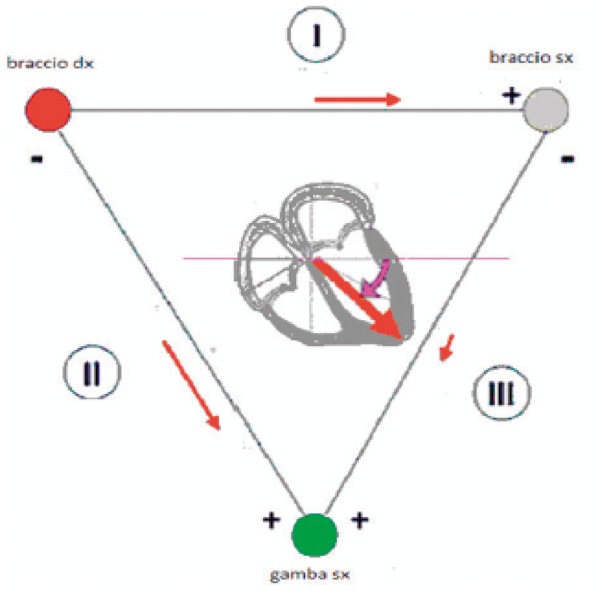
Einthoven’s triangle braccio dx, right arm; bracco sx, left arm; gamba sx, left leg.
Propagation of currents through the chest and limbs
The chest behaves like a volume conductor with a source of electrical fields within. Unlike what occurs in a linear conductor (e.g. a portion of a copper wire), in which an electrical impulse applied to an extremity propagates without substantial changes along the conductor itself, in a conducting volume within which is a distribution of electrical currents, various zones can have considerably different electrical potentials. This variety in behaviour, for example, accounts for difference between the electrical signals recorded by the electrodes placed in various positions on the chest (volume conductor) and the substantial invariance of signals measured in different parts of a limb (e.g. wrist, forearm, elbow, and shoulder).
Generally, the values of potential that can be measured on the chest will depend on the following factors:
Geometry of the volume conductor
Conductivity of the volume conductor
Distance from the source of the electric field
Orientation of the source
Intensity of the source
A first simplification necessary to understand the propagation of the electrical signal from the heart to the torso surface, is that of assuming that the propagation occurs through an electrically uniform medium, or in other words, assuming that the different tissues inside the torso have the same electrical characteristics (dielectric conductivity and permittivity). Though this approximation may seem imprecise (e.g. due to the presence of air in the lung cavity), results of experiments conducted on heart models in vitro demonstrate that the error which occurs upon assuming a uniform volume conductor is rather low. Starting from the hypothesis introduced by Einthoven (the electrical activity of the heart similar to an electrical dipole set in the centre of the heart, which in every instant changes its own direction and intensity) one may see that a couple of electrodes placed on the chest will measure potential differences that represent the projection of the vector dipole moment along the direction that joins the two electrodes (leads).
Einthoven defined a first system of leads as the differences of potential measured by combining electrodes in couples, placed on the right arm, on the left arm, and left leg (Einthoven’s bipolar leads). Lead D1 is obtained by connecting the positive pole of the potential meter to the left arm and the negative pole to the right arm; lead DII is obtained by connecting the positive pole to the left leg and the negative pole to the right arm; lead D3 is obtained by connecting the positive pole to the left leg and the negative pole to the left arm. The choice of the limbs as measurement points was dictated by technical motives: Einthoven did not dispose of electrodes and amplifiers and the measuring of the electrical signal came about by immersing the extremities of the body in a saline solution in metal containers. Since the limbs act as linear conductors, this situation is substantially equivalent to that of recording the signal at the level of the joints of the shoulder and the groin. Einthoven could thus retain the approximations as valid on the basis of his electrical dipole and triangular configuration theories (Figure 6). Subsequently, in addition to Einthoven’s leads, other leads were proposed and adopted (three bigger unipolar leads, or Goldberger, and six precordial leads). The three unipolar leads of the limbs are obtained by connecting the positive pole to a limb (aVR, right arm; aVL, left arm; aVF, left leg), while the negative pole is connected to the remaining limbs with the interposition of a 5000 Ohm resistance (Wilson’s terminal). The front surface was thus explored by six leads off-phased from each other by 30°.
Figure 6.
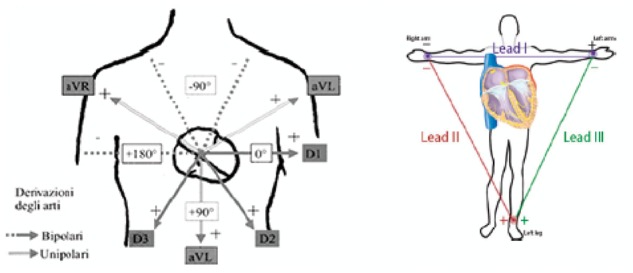
Peripheral leads Derivazioni degli arti, Lead of the limbs; Bipolari, Bipolar; Unipolari, Unipolar.
The unipolar leads of the chest (precordial leads) are obtained by connecting the exploring electrode in well-defined points of the chest:
V1: 4th intercostal space at the right edge of sternum,
V2: 4th intercostal space at the left edge of sternum,
V3: midway between V2 and V4,
V4: 5th intercostal space on the midclavicular line
V5: 5th intercostal space at left anterior axillary, and
V6: 5th intercostal space at midaxillary line.
The standard system of 12 leads commonly used today is, therefore, a complex method used to record the cardiac dipole along the various directions (and at different levels), so as to have a complete description of the activities arising from the overlapping of all the extracellular currents generated during a cardiac cycle (Figure 7).
Figure 7.
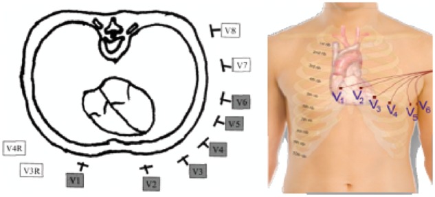
Precordial leads.
Besides the ECG leads, it is possible to use particular leads such as the thoracic tripolar leads or the oesophageal leads. The thoracic bipolar leads are obtained by positioning the two poles on the chest, thus obtaining three orthogonal leads (X, Y, Z) usually used for vectorcardiographs, high resolution electrocardiographs, and dynamic Holter recordings. The oesophageal leads obtained with both unipolar and bipolar techniques are particularly useful to identify the electrical activity of the atrium when this is not evident in the conventional waveforms; this aspect is particularly useful in cardiac pacing diagnosis, in which the identification of the atrial activation stands as the fundamental diagnostic element.
Acquiring the electrocardiogram signal: processes and filtering
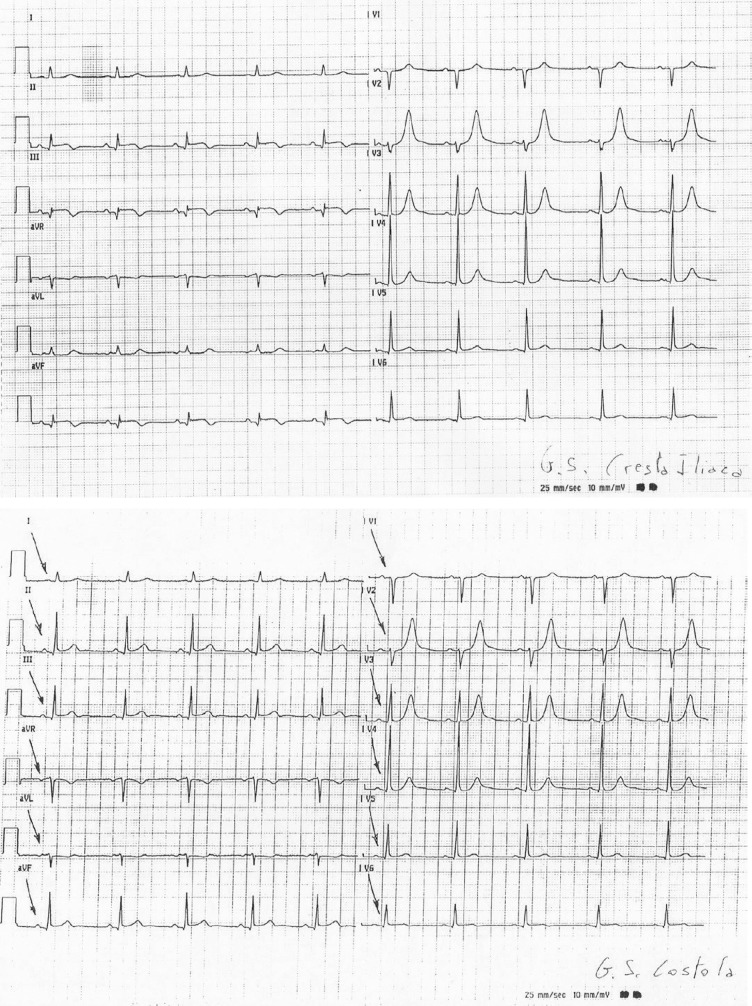
The ECG signal obtained through the standard 12 diagnostic leads is measured through standard electrodes placed on the limbs according to Einthoven (Einthoven’s triangle) with reference to the right leg and the Wilson precordial monopole leads. Therefore, ECG waveforms and related leads cannot be defined diagnostic if they are not acquired through 10 electrodes placed as in the diagram above and are not based upon diagnostic signals according to International Electricalal Committee (IEC)/EN1 norms and the guidelines for ECG2 standardization. We should recall at this point, the important potential medical-legal impacts when recommendations and international guidelines are breached.3 To obtain other data, one may also acquire right leads and rear leads, or choose other modes with reduced functions. For extended ECG stress tests, Holter, monitoring, and telemetries, chest leads can be used following standard placements—according to fundamental instructions—but artefacts may occur; this is important to know in order to limit the effects and improve the diagnostic results. Figure 8 shows two simultaneous wafeforms of the same patient but with different placements of the left leg electrode: only does the electrode on the iliac column explore the lower cardiac area. Similarly, one should pay attention not to excessively reduce the distance between the electrodes placed on the upper limbs. Other artefacts may be due to the bad placement of the precordial electrodes. A good placement of the precordial electrodes is fundamental for the diagnosis and control of the development in time of the ECG in relevant pathologies: if different positions are used for the following ECGs, incorrect conclusions may be drawn. Obviously, ECG signals achieved through pre-positioned electrode strips that do not take into account the different chest dimensions, cannot be considered as quality diagnostics: precordial electrodes must be used according to the standard placement. Along with the electrode placement errors, there may be environmental AC line noise due to faulty electrical systems or induced by equipment to which the patient is connected, e.g. contropulsers, monitors, etc. It would be advisable to take these interferences into account to remove the possible causes of bad signal acquisition. Other components that may induce artefacts especially in ambulatory patients are breast or abdomen prostheses or large-size breasts that may have a mechanical action on the electrodes. Therefore, in ambulatory patients placements should be found as close as possible to the bone level or similar, in order to find the area of minor muscle activation and reduce induced artefacts, including muscle tremor. As a rule the ECG signal is initially sampled at different tens of thousands of Hz per channel, so as to adequately identify the presence of a pacemaker, then the artefacts, the ectopic and sinus beats also at lower frequencies, by setting the memory up to 1000 Hz per channel to reproduce frequencies up to 300 Hz. The best LSB resolution is ideal up to some microvolts.
Figure 8.
Two different recorded electrocardiograms (EKGs) of the same patient at the same time, but with different positioning of the left leg lead. Note that only the positioning of the lead on the Iliac Crest can explore the inferior cardiac area. QRS voltage appears to be largely modified G.S. Cresta Iliaca, G.S. Iliac Crest; G.S. Costola, G.S. Rib.
Factors that affect signal quality
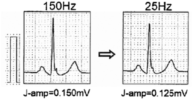
For IEC norms, the diagnostic ECG signal has to be captured with a bandpass equivalent to 0.05–150 Hz for diagnosing ischaemia, infarction, etc.4,5 Many other pathologies can be detected as long as the quality of the electric signal is respected; otherwise big diagnostic errors, invalidity, possible medical-legal consequences, and also greater induced costs are likely. Too many ECGs are performed without observing the norms and signal standardization guidelines, and it is by now not deferrable that all ECGs are performed according to the norms and guidelines.2,3 It is essential that also ergometry, Holter, telemetry and monitor waveforms always conform to the requirements of real (and not reconstructed) 12-lead diagnostic electrographs with bandpass of at least 0.05 Hz up to 150 Hz: these requisites must not be followed only on the simulators but on all the waveforms of the patients. This bandpass on various waveforms of the patients should be verified also on real waveforms in the test procedure. The diagnostic ECG signal must, therefore, be captured from 10 electrodes, at simultaneous 12-lead ECGs, 6 peripheral, or 6 precordial monopole leads as indicated above. For the guidelines of the American Heart Association/American College of Cardiology/Heart Rhythm Society (AHA/ACC/HRS)2 the bandpass filter must necessarily be at least 0.05 – 250 Hz for paediatric waveforms but in also for the late potentials, as mentioned recalled in the guidelines of the European Society of Cardiology (ESC) for the treatment of ventricular arrhythmia and the prevention of sudden cardiac death.6 Electrocardiogram signals may be morphologically altered by irregular filters or due to low resolution (segmentation of the waveforms), which generate false positives or false negatives. Many signal alterations may derive from the use of anomalous bandpass filters differing from 0.05 Hz: very serious are the errors in the interpretation of the ST segment, repolarization, branch blocks, and QT/QTc. Therefore, it is fundamental that the high bandpass filter cannot be modified by the operators, but be fixed and not modifiable, so as to avoid serious diagnostic consequences (Figure 9). Anomalous low-pass filters may also generate modifications: indeed, they may reduce the amplitude and the rapid ECG components, jeopardizing the recognition of possible risk factors of cardiac arrest such as delta and epsilon waves, and fragmentations of the QRS (Figure 10). Therefore, it would be advisable to use a bandpass always ranging between 0.05 and 250 or 300 Hz. In any case, for diagnostic purposes it is fundamental to analyse only ECGs that have been acquired with a bandpass that cannot be reduced below the intervals of 0.05 to 150 Hz for standard ECGs. This requisite is also recommendable for ECG stress test systems, Holter systems, telemetries and monitors.
Figure 9.
Effect of a different filtering of the electrocardiogram signal. On the left, a bandpass filter up to 150 Hz was used, on the right, a filter of <25 Hz was used. Some QRS components appear to be significantly modified.
Figure 10.
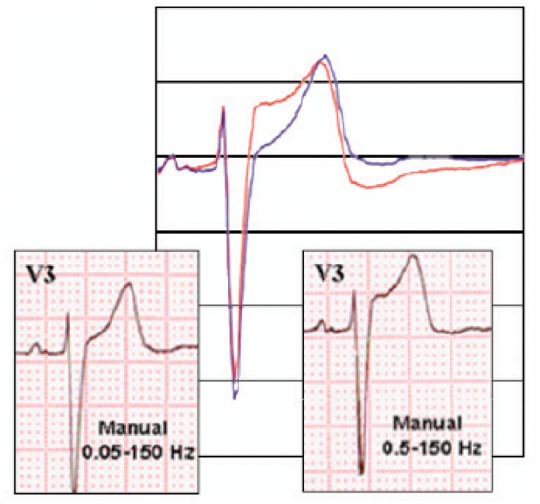
Effect of a different filtering of the ECG signal. On the left, a bandpass filter between 0.05 and 150 Hz was used, on the right, the filter used was 0.05–150 Hz. Some components of the ST segment appear significantly modified.
Critical factors in morphology and rhythm analysis
Analysis of the morphology and rhythm constitutes the fundamental aspect of monitoring in whatever way it is done or acquired. Through the description of these two parameters one can gather all the necessary elements to provide a diagnosis, recognize events occurring in the heart, set alarms, and organize assistance. Analysis of the morphology and rhythm requires a stable electric signal that responds to established international quality requisites. As a consequence, the set of elements ranging from capturing the signal on the patient to displaying it on the monitor must be considered important. The electric signal is indeed the result of a careful preparation of the patient’s skin, an interface electrode with certified quality, transmission through various connections to the recording device and analysis of the signal, the type of algorithm(s) used for filtering, presenting, and displaying (Figure 11). It is therefore clear that the final display of the signal to be analysed is, in fact, the result of a series of upstream processes.7 Each of these processes may irreversibly alter the quality of the signal and make it difficult or impossible to obtain a correct analysis of the rhythm and the morphology of the waveform. Subsequent to this, malfunctions like false alarms and recognition errors may arise and delay clinically important interventions, cause wrong interpretations in sensitive settings such as the intensive care, or prevent some procedures (e.g. transcutaneous, pacing, and synchronized cardioversion), invalidate tests (dynamic ECG) or even make them hazardous by hiding important information or simulate non-existent pathological conditions (ergometric tests).
Figure 11.
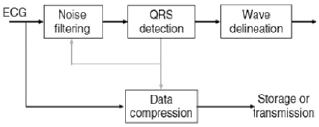
Chart of the heart’s electric signal processing by electrocardiogram recording systems.
The morphology and final stability of the ECG waveform in diagnostic equipment need some steps that start with signal acquisition, continue with its elaboration, and end with its display.2
An important critical factor consists in the interface between the electrode and the skin: the preparation of the skin is vital to reduce the resistance and diminish the artefacts. In the patient-electrode interface, it would be recommendable to use exclusively disposable electrodes for the 10 leads. First of all, the capacity of the electrode to stick to the skin must be checked. When hair is present, it is advisable to shave it off only in cases of abundant hair and in situations where it largely interferes with signal transmission. Shaving should be preferably done with no-blade systems, to avoid skin abrasions and wounds. In the presence of sweat or moist skin, suitable washing and drying need to be done first. In case of ‘clip’ electrodes, the wire of the electrograph should be connected to the disposable electrode and subsequently placed on the acquisition point. In case of clamp electrodes, it is necessary to connect the electrodes to the patient’s chest first, and then connect the electrograph wires. Avoid applying the electrodes to skin sites with erythema/lesions/wounds. All types of diagnostic ECG signals have in common a set of algorithms that eliminate noise and artefacts, recognize the heartbeats and capture the basic ECG in its fundamental characteristics of duration, amplitude of the various components, and finally compress data for possible archiving and transmission. Filtering is a very important aspect since it has to remove the external electrical interferences and breathing-induced movements. The elimination of muscle noise is more critical, due to an overlapping in the frequency spectrum between the ECG electric signal and that of the muscle. However, the ECG signal is a recurrent signal and, therefore, what makes it distinguishable from the one connected to the electrical activity of the muscles.
Another important element is detecting the QRS signal. An error in its recognition causes a poor performance of the entire system and yields low quality waveforms. Once the QRS is well defined by means of further algorithms, it is possible to recognize ventricular repolarization and the P wave. The acquisition of the ECG signal produces a huge amount of data that requires compression for display, transmission, and archiving. The objective of all the systems is to capture the signal in the most faithful manner possible to the original with less bit consumption. This is achieved with data compression that, however, limits the distortion to acceptable terms. To do so, filters are applied before data compression. The fundamental frequency for the QRS complex at the level of body skin is equivalent to approximately 10 Hz and most diagnostic information is below 100 Hz. The fundamental frequency of the T wave, on the other hand, is approximately 1–2 Hz. The filtering of the ECG signal with a bandpass between 1 and 30 Hz produces a stable signal free from artefacts. However, the wavelength explored is not suitable for ECG signal studies since it distorts both the low and high frequency components. The high frequency components are those that change more rapidly like the QRS. As mentioned above, a reduced quality of QRS acquisition invalidates the entire waveform, produces an underestimation of the amplitude of the signal, and reduces the accuracy of description of the Q wave and the irregularities that may occur. On the other hand, an inadequate low-frequency response significantly distorts repolarization. Therefore, the ‘transfer function’ of the filtering algorithms of analogic and/or digital devices greatly affects the morphology of the ECG waveforms.2
All modern electrocardiographs pass from analogic signal to digital signal through data conversion. The quality of the signal obviously depends on the quality of the acquisition but also on the frequency of the sampling in the analogic-digital conversion. The new devices carry out the conversion at frequencies of 10 000/15 000 per 2nd and beyond. Some convertors are adaptive and respond in a differentiated manner to the energy of the acquired signal. The oversampling of the signal allows for the recognition of very fast waves, e.g. pacemaker spikes. The low frequency signal indiced by breathing may be eliminated through the use of low-frequency filters, but these may distort the signal, and cause marked alterations of the ST segment. Modern digital systems allow the filtering of baseline fluctuations without altering the original signal.
To reduce the noise and improve signal quality modern digital systems produce ‘templates’ of the acquired leads, which represent the form of that lead in a faithful and clean manner. In doing so, small beat-to-beat variations are lost in the amplitude of the signal, variations that may be relevant to the acquisition of QRS variations in time, or of T wave alternance. Consequently, the way and the quality with which these templates are constructed are essential. The compression of the ECG signal requires the use of mathematical transforms that compress the signal by many factors with high, but not absolute, fidelity, and may affect high-frequency signals, thus altering the electrical signal (spikes of pacemakers; QRS, R wave amplitudes). The ST segment and the T wave are less susceptible, and the compression with loss-less algorithms of the signal allows, with greater precision, for the fast transmission of signals, also for monitoring and Holter tests, and easy memorization. This may be important in the comparison of waveforms, especially between those archived and those performed on the spot. Also in this case, compliance with the strict standards can minimize this effect. Skin preparation and electrode placement are very important, since they may impact on the amplitude and the electrical axis of the waveforms. The simple measurement of the signal by placing the electrodes at the base of the limbs instead of the wrists and ankles may bring about important changes in the morphology of the ECG. Obviously a different positions of the electrodes on the chest may determine a different morphology than the precordial leads. In short, many artefacts that may affect the analysis of rhythm and morphology depend on technical factors, the use of filtering algorithms, and different samplings. In addition to these factors there are others, more specific to the different devices used, whether monitors, electrocardiographs, ECG Holter systems, etc.
In the case of monitors, we must underline, by way of example, that wireless systems, if qualitatively adequate, may produce a delay between waveform acquisition and display. Also the architecture of data gathering and transmission in the Wi-Fi networks that are connected to the monitoring devices may cause such anomalies. In these cases, delays must be acknowledged and kept in mind in the choice of patients to be monitored because it may cause critical problems to them.8
Main technological solutions: interpretations and automated medical reports. Precision of electrocardiogram signal analysis
The ECG signal in its various forms is at the basis of diagnostics due to its precision, accuracy, functional rapidity, non-invasiveness, strict standardization, cost effectiveness, and the time range of the analysis.
It is fundamental for the diagnosis of arrhythmias, and their types and risk factors (starting with the recognition and identification of an ectopic focus, late potentials, long or short QTs, and pre-excitations), in cardiomyopathies, ischaemic cardiopathy, in the diagnosis of myocardial hypertrophy, in the assessment of the presence and functioning of pacemakers, in the recognition of channelopathies or electrolyte disorders, in some genetic diseases, and in the activities of some pharmaceuticals. The importance of a qualitative approach to ECG diagnostics is evident. The new ESC6 guidelines for the management of ventricular arrhythmia and the prevention of sudden death, require the use of simultaneous 12-lead Holter ECG with the analysis of the ST segment and the QT/QTc interval. This recommendation is more important in patients with acute pathologies that need bedside or telemetry monitoring. Analysis of simultaneous 12-lead ECG is fundamental also to identify possible ectopic foci and their position, so as to decide whether to refer the patient to ablation, thus reducing the intracavitary mapping time. Only relying on qualified amplifiers, systems for the removal of the artefacts, precise automated measures, descriptive automated interpretations, and differential analysis of the development of pathologies, can clinicians hope to take effective action in the stratification and treatment of cardiovascular pathologies, while rationalizing costs and respecting the patient’s safety. The automated interpretations must not be of poor quality. Cost effectiveness must not create compromises with the precision of the algorithms and solutions employed. The automated interpretation of the ECG signal has by now reached a good standard, both regarding the rhythm and the morphology of the waveform. Nowadays we can rely on high precision systems also for the analysis of the ST segment as well as surface ECG and on Holter tests, ergometry, telemetry and monitoring, all of them with the memorization of continuous, real-time 12-lead ECGs. Another fundamental measure to take into consideration is the QT and QTc, which, according to Bazett and Fridericia, are risk factors in the triggering of arrhythmia. Automated differential analysis is essential in checking the development of pathologies. The ANSI/AAMI9 guidelines are fundamental for their approach to the precision of algorithms and the measuring of ST segment and heart rate.
Automated electrocardiogram recording
Electrocardiographic devices can record waveforms in real time or automatic mode. This is possible thanks to the development of digital techniques for signal processing. The signal is captured by the device and then displayed after being processed with a variable delay that may be used to improve the quality of the waveform itself, present it in groups of leads (3/6/12), associate it to the calculation and printout of measurement parameters (e.g. heart rate, PR, QT), or even add an automated report. During digital acquisition it is possible, as already described in this document, to use special
filters that are able to correct the fluctuation of the baseline, thus preserving fidelity in the reproduction of lower frequencies. The alterations of the ST segment and the T wave that could be eliminated by an unsuitable filtering at the low frequencies in real mode can be partially modulated by modern digital electrocardiographs on condition that one accepts a delay between signal acquisition and printing, to allow for post-acquisition signal processing. In the automated mode, therefore, the presentation of the waveform is delayed compared with the acquisition, a delay which the system uses for digital processing. This mode prevents the instantaneous real-time acquisition of the 12 leads, which may be important during the assessment of arrhythmia or of time-dependent phenomena (e.g. QT alternance). It is important that the operations and filterings used are clearly explained in the automatic mode in order to comply with the international norms or recommendations, it is clearly stated which may instead cause distortions. Another important aspect is that in no case should the device provide only the automated registration mode, precisely in order to forestall problems related to delayed recording and post-processing, especially if not clearly described; that may be used to improve the quality of the device and algorithms rather than complete the offer of the device.
Electrocardiogram automated reporting
Modern electrocardiographs, monitoring central stations, Holter ECG devices are equipped with algorithms for automated signal analysis. In the case of monitoring stations and Holter systems, the analysis addresses mostly (but not exclusively) the recognition of heart pace disorders. Moreover, there are algorithms used above all in the analysis of the ST segment to detect dynamics that may imply ischaemic alterations. The criteria and recognition thresholds can be modified by the operator to respond to clinical needs. In the case of electrocardiographs, automated recording deserves a separate and brief explanation, since it has become a very common and recommended aid in reducing the need for specialized cardiological treatment. These devices use computerized interpretative algorithms that employ different criteria, generally based on extensive reference databases. However, despite technological improvements and experience, there are many critical aspects that must be taken into account when turning to automated interpretations of ECG waveforms.10 Firstly, as of today there is no error-free system and the changeability and variety of ECGs constitute a source of many other interpretative problems. We know for example that ECG waveforms differ according to age and gender. The erroneous recognition of a simple arrhythmia (such as atrial fibrillation) may have important consequences on clinical options and therapeutic choices.11 Furthermore, the widely diffused experience is to generally and reasonably trust and rely on automated diagnosis, reserving greater attention to the necessary validation of the waveforms identified as abnormal. As to the use of ECG transmission systems, the same care is needed in being aware that an error made in the presence of an acute coronary syndrome may have important consequences. In a trial conducted in Scotland,a modern ECG transmission system employed for suspected myocardial infarction with a ST segment elevation, though showing good clinical efficacy, turned out to be less sensitive in the correct recognition of the heart attack (though with greater specificity) than the hospital cardiologist.12 The Panel retains that automated recording of ECG waveforms is a potentially useful support system to correct diagnosis. However, it is important to underline the importance of editing the recording and obligatorily validate it. Such measures are particularly important for clinical implications, and the correct collection and management of patient data.
Fundamental recommendations for the purchase of diagnostic devices
The purchase of devices should be done in compliance with the norms in force and the best competitive tenders, with the exception of those with remarkable technological and innovative features, and that are certified and fully compliant with the requested characteristics, according to this document. Attention must be paid, therefore, not only to lower prices, but also to careful verification of the quality, or rather, the precision of the signals (memorized, displayed, and printed) of the measurements and automated interpretations: one single error may cost more than the purchased devices, with serious medical-legal repercussions.
Low-quality devices may cause important diagnostic errors.
Electrocardiographs
Acquisition of a simultaneous 12-lead ECG.
Electrocardiogram signal bandpass for printouts and memory from 0.05 to 250 Hz with proven functionality of good quality waveforms on patients.
High precision measurements and automated interpretations from nenonates to aged patients, instructions for the various types according to the standard descriptions from 2007 to 200913–16 also integrated with definitions and automated criteria of Brugada channelopathy type 1 pathological ECG, type 2 and 3 borderline ECG.
Manufacturer’s EC Mark.
Approval by the Food and Drug Administration (FDA), an important institute quality mark.
Dynamic Holter 24–48h electrocardiogram system
Acquisition of simultaneous 12-lead ECG.
Measurement with less leads may be reused on heart failure or long-term pathologies.
Bandpass of the ECG signal for printouts and memory from 0.05 up to 250 Hz with proven functionality for good quality waveforms on patients.
High precision automated measurements particularly for heart rates, S/T and QT/QTc from paediatric patients to aged patients, at least according to Bazett and Fridericia.
loss-less algorithms for the reduction of the space occupied by the files, which reduces storage time and allows for fast distance transmissions.
Manufacturer’s EC Mark.
Approval of the FDA, an important institute quality mark.
Ergometry
Acquisition of simultaneous 12-lead ECG.
Electrocardiogram signal bandpass for printouts and memory of 0.05 to 150 Hz with proven functionalities for good quality waveforms on patients. Quality algorithms for the reduction of artefacts due to breathing and muscle tremor.
High precision automated measurement particularly for rhythm, S/T and QT/QTc from paediatric patients to aged patients, at least according to Bazett and Fridericia.
High precision supine ECG automated interpretation, description of the different types according to standard provisions from 2007 to 2009,13–16 also integrated with definitions and automatic Brugada channelopathy type 1 pathological ECG, type 2 and 3 borderline ECG.
Manufacturer’s EC mark.
Approval of the FDA, an important institute quality mark.
Telemetries and monitoring
Acquisition of a simultaneous 12-lead ECG.
Invariable bandpass ECG signal for printouts and memory from 0.05 to150 Hz with proven functionality for good quality waveforms on patients.
Quality algorithms for the reduction of artefacts due to breathing and muscle tremors.
High precision automatic measurement particulary for heart rates, S/T and QT/QTc from paediatric patients to aged patients, at least according to Bazett and Fridericia.
High precision supine ECG automated interpretation, description of the different types according to standard provisions from 2007 to 2009,13–16 also integrated with definitions and automated Brugada channelopathy type 1 pathological ECG, type 2 and 3 borderline ECG.
Automated control in the development of pathologies.
Precision in the alarms also of the ST and QT/QTc.
High reduction of false alarms or clinically insignificant alarms.
Memorization of beat-to-beat ECG waveforms for the hospitalization period for telemetries, together with other signs such as invasive and non-invasive arterial pressure, SpO2, and temperature.
Manufacturer’s EC mark.
Approval of the FDA, an important institute quality mark.
Compliancy with ANSI/AAMI EC57:2012.9
Artefacts and their control
How to perform an electrocardiogram correctly
When performing an ECG, conditions may arise to determine disturbances or artefacts on the ECG waveform, and often prevent correct analysis. The causes may be external to the patient as in the case of interferences due to alternating current, internal to the patient as in the case of muscle tremors, or the incorrect preparation of the test as in the case of unstable isoelectric lines.
Interferences due to alternating current
This is a distorsion of the ECG caused by alternating current supply which produces a stable frequency vibration (50–60 Hz) that overlaps with the waveform. The causes of such interference are to be traced back to the presence of intense electromagnetic fields that may be generated by devices in the vicinity (X-rays; radar-therapy, etc.) or electromagnetic fields provoked by neon lights or electrical distribution lines, bad grounding connections, a power cord intertwined with the patient cable, and breakage of a conductor of the patient cable. This type of problem can be solved by eliminating, wherever possible, the source of noise or setting grid filters in the electrocardiograph.
Muscle tremors
The ECG waveform appears to be studded with small segmentations that at times impede the correct visualization of depolarization waves. They may be caused by the tremors of the patient or due to a cold room, a tense patient, diseases like Parkinson, or a bad electrode-skin contact. In this case, there is a broader correction margin, e.g. creating a more comfortable environment for the patient. The table should be wide enough to allow the patient to relax his/her muscles and extend his/her arms in a relaxed manner. It would be important to advise him/her to relax. In the case of patients with pathologies like Parkinson’s, it would be better to put the patient’s hands under his/her buttocks; in this manner the tremor of the arms will remarkably diminish.
Instability of the isoelectric line
Electrocardiograms in this case are characterized by remarkable fluctuations of the waveform. The cause may be a bad electrode-skin contact following a scarce use of the conductor (gel, saline solution, or just water) or loose electrode clamps. Other causes may be the presence of foreign bodies, like metallic parts between the electrode and the skin. The correction of this type of artefact consists in positioning the peripheral electrodes on prominent bones to avoid muscle noises and use a sufficient amount of conductor, keeping the zones involved free from metallic materials (bracelets, watches, etc.), and keeping the wires of the patient cable free to prevent entanglement. Lastly there are also filters available on the electrocardiograph. However, the filters used to avoid artefacts on the ECG can conceal small deflections that are important when assessing the ECG—e.g. spikes, which indicate a pacemaker stimulus—or excessively smoother the isoelectric line and modify the elevation of the ST segment when anomalous, non-diagnostic filters are used. The AHA has issued a recommendation regarding the use of the frequencies of ECG filters for adults and paediatric patients. The most preferable frequencies are those up to 150 Hz for adults and up to 250 Hz for paediatric patients.2
Bedside monitors
Bedside monitors are used to monitor ECGs of unstable patients. ECG monitoring, unlike standard 12-lead ECGs, do not allow a detailed interpretation of the morphology of the complexes and alterations of the ST segment, including myocardial ischaemia, unless these comply with the characteristics given in the previous paragraph for diagnostic monitoring. This checks the heart rate, the heart rhythm, and the presence of arrhythmia. The bedside monitor is connected to the patient by means of three wires recognizable at the distal
extremity thanks to the colour of the electrodes (yellow, red, and green). At times two other wires (black and white) are used to measure the preipheral unipolar leads and for a precordial lead (in V1 the P waves are visualized better). The electrodes have to be placed on the chest after washing the skin, since they remain in place for a variably long time and bad contact could generate a series of artefacts. They should be positioned on prominent bones, rather than on muscles, as they stay more stable and reduce the artefacts of muscle noise, according to the following scheme:
Right leg (RA) electrode (red): below the right clavicle, on the mid-clavicular line,
Left leg (LA) electrode (yellow): below the left clavicle, on the mid-clavicular line,
Left leg (LL) electrode (green): lower left at spleen level.
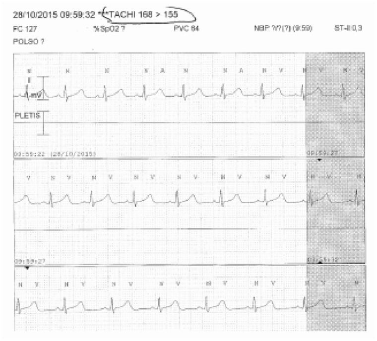
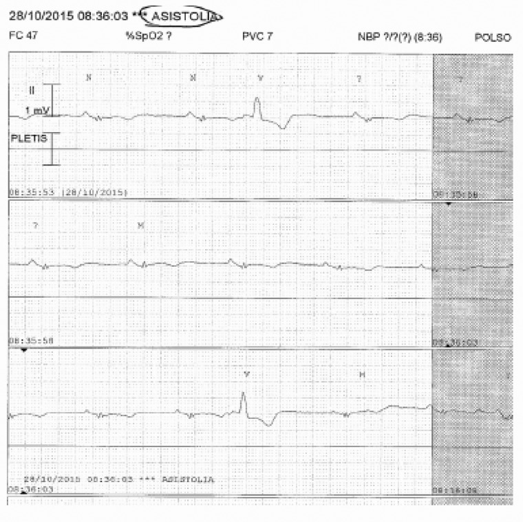
The lead to be preferred is dipolar lead II (DII), as it reads the lead parallel to the electric depolarization axis of the heart; the P waves are very clear and the QRS well visible. At times you will need to change lead to avoid undersensing phenomena (false asystole) or modify the amplitude of the signal. It would be good to pay due attention to electrode-skin contact, as poor contact would determine over-sensing phenomena (false tachyarrhythmia).
Ergometry tests
During ergometry tests, the ECG waveform may have problems in all ways similar to those encountered when carrying out a standard ECG. Specifically, to avoid isoelectric instability it would be advisable to prepare the skin carefully so as to have the best electrode-skin contact. The skin should be cleaned with alcohol and the electrodes placed in proximity of prominent bones; as far as peripheral leads are concerned, the dorsal zone should be preferred to the anterior chest zones. To avoid muscle tremor, the electrodes and the patient cable wires should be fixed so that they do not follow the movements of the patient during the test. Moreover, the patient has to be advised not to contract his/her muscles, or make any effort with his/her arms, but use them only to stay balanced and maintain the chest erect.
Dynamic Holter electrocardiogram
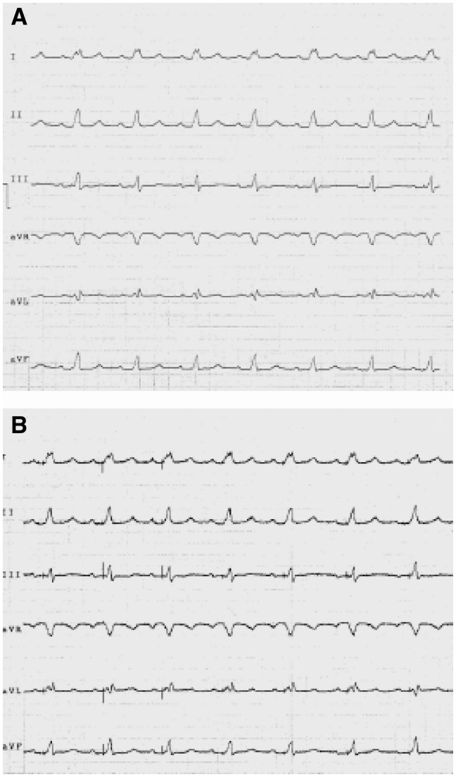
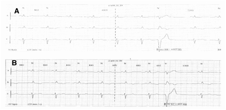
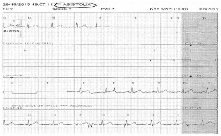
As to the 24 or 48h dynamic Holter ECG, the recommendations are mostly the same as those for the bedside monitors. The electrodes must be placed over prominent bones after cleaning the skin with alcohol, and be kept secured with a band-aid. Also the wires of the patient cable have to be secured to avoid movements that create muscle tremor artefacts. The modern systems that offer three or more recording channels, allow operators to choose the channel that acquires an ECG waveform valid for interpretation, thus avoiding over/undersensing or the instability of the waveform. If this cannot be achieved, it is possible to move the electrode(s) until a suitable configuration is reached. Figures 12–18 show some paradigmatic examples of otherwise resolvable artefacts.
Figure 12.
(A) High filter waveform with no artefacts. The apparent diagnosis is sinusal rate with left branch block. (B) This waveform is the same as the previous one but with minimized filters. It is evident that the spikes of the pacemaker are visible. The correct diagnosis is good functioning of the atrial-guided pacemaker.
Figure 18.
The Holter waveform (A) shows an R–R interval of 4005 ms. In reality, this deals with an R wave undersensing phenomenon due to a low signal. In waveform (B), where a different reading channel was selected, the R waves are all measured and the R–R intervals are set at about 860 ms with minimum variations PAUSA RR, R-R INTERVAL; BEV I.C., VEB C.I.
Figure 13.
In this image, a bedside monitor waveform with false asystole rhythm diagnosis provoked by the detachment of an electrode ASISTOLIA, ASYSTOLIA; PLETIS, PLETHYS.
Figure 14.
Bedside monitor, waveform done with capture of ventricular tachycardia. In reality, a dual count of the R waves occurs following an oversensing of the T wave. The phenomenon can be solved by changing lead TACHI 168 > 155, TACHY 168 > 155; POLSO, WRIST; PLETIS, PLETHYS.
Figure 15.
Bedside monitor, waveform with detection of a false ventricular tachycardia provoked by a partially detached electrode.
Figure 16.
Bedside monitor waveform measuring a false asystole rhythm due to R wave undersensing phenomena. It is corrected by augmenting the signal amplitude ASISTOLIA, ASYSTOLE; PLETIS, PLETHYS.
Figure 17.
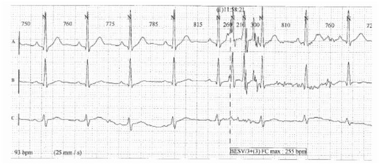
A Holter waveform with false measurement of a ventricular tachycardia runs. These artefacts are found only on waveforms (A) and (B), while waveform C is clean.
International standards, guidelines and norms in force
International standards
Recording of an ECG signal and its viewing on a display or printout for a correct diagnosis on the part of clinicians need a technical assessment of the interpretative process done by the medical devices, whether electrocardiographs or Holter systems or monitoring devices. Since 1998, the placing of medical devices on the market within the European Community has been governed by strict and obligatory regulations laid forth by the Medical Devices 93/42 directive, later emended, which, for the ‘presumed compliance to essential safety requisites’, refer to the standardized norms published by CENELEC; these norms generally recognize and adopt the technical documents developed by international bodies such as the International Electrical Committee (IEC). Though the compliance with the norm is not an obligatory requirement, the technical norms are a benchmark for all the manufacturers to define the correct design of the equipment.
The reference norm for all the medical electrical devices is the IEC 601-1 (also transposed as the European norm EN 60601-1)17 now at its 3rd edition and that, for the most widespread and critical equipment, is accompanied by particular, specific norms. Currently, for equipment used in the processing and display of ECG signals, the IEC has published three different specific norms:
IEC 60601-2-25:2011 (2nd edition), Medical electrical equipment—Part 2-25: Particular provision related to basic safety and essential electrocardiograph performances;
IEC 60601-2-47:2012 (2nd edition), Medical electrical equipment—Part 2-47: Particular provision related to basic safety and essential performances of ambulatory systems ECG (Holter);
IEC 60601-2-27:2012 (3rd edition), Medical electrical equipment—Part 2-27: Particular provision related to basic safety and essential performances of ECG monitoring equipment.
These norms modify and complete the IEC 60601-1 (3rd edition, 2005), Medical electrical equipment—Part 1: general provisions related to basic safety and essential performances later called ‘general norms.’
We underline that the general norm, from the 3rd edition, defines provisions not only regarding basic safety but also the essential performances which the equipment has to guarantee. Details of essential performances are obviously given in the particular norms and all the three norms cited; among the essential performances of a device, the frequency response is provided in very precise terms and must be definitely given in an unambiguous way by the manufacturer. The ECG signal captured has a frequency content which, if not processed correctly, may lead to loss of important information, important morphology alterations and false positives/negatives. The application of filters to the recorded signal, filters that obviously may also introduce distortions must always be considered and assessed before performing a diagnosis.18,19
Guidelines
There are many publications on this topic, but even before this aspect was regulated by the IEC, a great number of recommendations had been published for the standardization of ECG recordings with guidelines for their interpretation aimed at keeping abreast with technological advances. One of the referral bodies in matters of international recommendations is undoubtedly the AHA, whose latest edition of the guidelines for the standardization and interpretation of ECG signals dates back to 2007.2 That edition confirmed the instructions developed by the Association for the Advancement of Medical Instruments on the processing of ECG signals, with the following content.
Traditionally,20–23 in matters of high frequency cut-off, a value equal to 0.05 Hz was recommended for diagnostic applications in the attempt to ensure minimum or zero distortion phases that may occur at 0.5 Hz (10 times more) and beyond. The topic of low frequency response was discussed in the 199024 AHA edition of recommendations, which underlined that a low-frequency cut-off equal to 0.05 Hz preserves the faithful reproduction of repolarization, but does not sufficiently suppress the oscillation of the baseline. On the other hand, it underlines how ECG systems with greater cut-off frequency introduced unacceptable non-linearity phases with consequent distortions of the ST segment. Though continuing to retain that high pass filters with cut-off equal to 0.5 Hz can distort the ECG signal, these suggestions contrasted to those of the previous editions, in which the low frequency response was traditionally defined in terms of low frequency cut-off at 0.05 Hz. With the development of digital signal processing techniques, designers could avail of devices that were able to increase high-pass cut-off frequency without introducing distortions; in other words they were able to design new digital filters able to correct the oscillation of the baseline, though preserving fidelity in the reproduction of the slow contributions. The introduction of these digital methods lead to amending the standards required for analogical filters. The 1990 recommendations, in conclusion, to reduce the distortions that create artefacts in the ST segment, continued to recommend a cut-off at low frequencies equivalent to 0.05 Hz for classical filters, with the possibility of extending this requisite to 0.67 Hz or to lower frequencies for linear digital filters with null phase distortions. The latest AHA13 recommendations continue to recommend the standards defined in the 1990 edition, in these terms: ‘filtering in a traditionally analogical manner, a high-pass cut-off equal to 0.5 Hz will introduce considerable distortion in ECG recordings, particularly with reference to the ST segment level. This distortion originates from phase non-linearity which occurs in the ECG signal areas where the content in frequency and the amplitude of the wave rapidly change, as occurs where the end of the QRS complex meets the ST segment. The digital processing of the signal provides methods for the increase of the high-pass frequency cut-off without introducing phase distortions. This approach may be applied only to ECG signals that are stored in the computer’s memory, with the introduction of a time delay, and not in situations of temporary monitoring.’ Recent studies confirm that the marked distortion of the ST segment, expected with improper cut-off at low frequencies, may be partially modulated by modern digital electrocardiographs by accepting the reintroduction of a delay between signal acquisition and printout, in order to allow for post-acquisition signal processing.
In matters of low frequency cut-off (in high frequency) it is traditionally known that25–27:
errors in amplitude of the Q, R, and S waves are directly correlated to the characteristics of high frequency response: in general, the errors increase with the decrease of cut-off frequency;
amplitude values are reduced with the diminishing of cut-off frequency;
the duration of the QRS complex is relatively little affected by the performance in high frequency of the measuring system, but important variations for cut-off frequencies below 60 Hz are detected.
Some studies conducted in the 1960s stressed that errors in amplitudes >50 μV may appear in more than 10% of the recordings using a low-pass frequency cut-off equal to 100 Hz to record ECGs of adults and equal to 150 Hz for paediatric ECGs. The use of a low-pass frequency cut-off much greater than 100 Hz, probably of 200 Hz, was recommended to keep amplitude errors below 0.05 mV. Other studies even claimed that a bandpass extended up to at least 500 Hz was needed to reproduce all the components of the high frequencies measurable. More recent studies have shown that to keep the errors of amplitude below 25 μV for more than 95% of the cases, it is necessary to extend the bandpass up to 250 Hz for paediatric cases and up to 150 Hz for adolescents and adults. The necessity to adopt these value limits was recognized at international levels, as confirmed in the AHA recommendations of 2007:2 the value of low-pass frequency cut-off therefore corresponds to 150 Hz for adults and adolescents, with an extension of 250 Hz for paediatric patients.
Table 1 summarizes the characteristics of frequency response that an electrocardiograph has to possess in relation to the various intended uses. This information can be found in the documentation accompanying the device, wherein the manufacturer must indicate the possible types of filters applicable to the signal, specifying which comply with the norm provisions or international recommendations and which instead risk to introduce distortions in the waveform. In the case where the response to the low frequencies are indicated not in terms of high-pass cut-off frequency but, for example, in terms of more or less marked suppression of the baseline shift, it is necessary to verify what frequency cut-off values these definitions correspond to with the manufacturer, so as to weigh its applicability or not in relation to the specific intended use.
Table 1.
Characteristics of frequency response that an electrocardiograph should have in relation to the various intended uses
| Aim | Age of patient | Mode | High pass filter (Hz) | Low pass filter (Hz) |
|---|---|---|---|---|
| Diagnostics | Adult | Manual | 0.05 | 150 |
| Diagnostics | Adult | Automatic | 0.05–0.67To be defined | 150 |
| Diagnostics | Child | Manual | 0.05 | 250 |
| Diagnostics | Child | Automatic | 0.05–0.67To be defined | 250 |
Lastly, it would be important to pay special attention to possible filters of the EMG type or for muscle tremors, that have the effect of reducing the bandpass to a frequency much lower that 150 Hz, with values of low-pass cut-off frequency that are unacceptable for diagnostic applications.
Therefore, a precise definition of the intended use and careful analysis of the documentation accompanying the device are the first steps in defining the suitability of the performances issued. This is why the problem must be well known and faced not only by the manufacturers but also by the Hospital Technical Service28 who are responsible for maintenance, and by the medical-nursing staff who have to use the equipment at best, and are aware of the limits and setting modes.
During the assessment and acquisition phase it would be fundamental to define the intended use of the device with the specification of whether the electrocardiograph, Holter system or monitor in question will be for ECG recordings, what type of patients it is assigned to (adults, paediatric, and neonatal), and in what facilities they will be used (offices, ambulances, and home care).
This information should be defined upstream in the purchasing process so as to determine the characteristic that the device must have in order to suit the intended use, compared with what the manufacturer declares in the documentation accompanying the device, as well as verifying its compliance with IEC norms.
In short, accurate reproduction of ECG signals that allows diagnostic evaluations obtained by the interpretation of the waveform, require a sufficiently ample bandpass. In particular, it is necessary to have a good response to high frequencies to be able to accurately reproduce Q, R waves and details of the waves (fast contributions), while it should give a good response to low frequencies to accurately produce slow contributions like the ST segment, with attention to both the level and inclination.
The use of frequency filters may cause such distortions of the ECG signals as to hinder a sufficiently accurate representation of important aspects from the diagnostic viewpoint, which are fundamental for a correct interpretation of the ECG. The use of improper filters may in fact improve the visual appearance of a signal but not its diagnostic value. The filtering effect should, however, be maintained at such levels to prevent the onset of deterioration of the faithful reproduction of the signal.
A final technical aspect to be considered in the correct definition of the minimum requirements of digital electrocardiographs is the sampling rate. The frequency of low-pass cut-offs and sampling are strictly related to the Shannon theorem, according to which the bandpass of the incoming signal to the analogic-digital converter must not be greater than the Nyquist frequency, defined as equivalent to half of the sampling rate. Recalling the definition of cut-off frequency for real filters, in correspondence to which there is a decrease of 30% or equivalently of 3 dB compared with the bandpass, the Nyquist frequency will have to be much greater than the low-pass cut-off frequency, so as to guarantee that in correspondence with the Nyquist frequency there will be no contributions belonging to the signal or to noises overlapping with it, which would provoke equivocations in frequency.
Since the value of 150 Hz is recommended for the low-pass cut-off frequency in ECG systems for applications on adults, 250 Hz should be a common option for the Nyquist frequency with sampling at 500 Hz.
For applications on paediatric patients, for which the low-pass cut-off frequency must be extended to 250 Hz, using a sampling rate equal to 500 Hz would imply an equivocation in frequency: to avoid this phenomenon, a greater sampling rate is needed, typically equal to at least three times the maximum frequency contained in the incoming signal to the analogical-digital converter.
These specifications concur to form the necessary competencies to critically analyse what is declared by the manufacturer, and compare the value of sampling rates with the different types of low-pass filters offered to the user: possible incongruences will be highlighted and, consequently, it will be possible to request more information to this regard (e.g. low-pass filter of 300 Hz compared with a sampling rate of 500 Hz).
Norms in force
The simple evaluation of information provided in the documentation does not suffice, since the correct management of technologies should include a technical functional test. Traditionally, the acceptance test includes safety electric measures in compliance with the specific CEI EN 62353 norm, but the same norms also refer to the need to carry out functional checks, or rather performance tests, of those characteristics that may affect safety. The same norm indicates, among the performances to be tested, those listed as essential requirements in the specific norms, and all the aforesaid particular norms IEC 60601-2-25, IEC 60601-2-27, and IEC 60601-2-47, which include the definition of the band frequency response among the essential requisites. In short, the technical test of the frequency response declared by the manufacturer must be carried out during the test phase; the same applies to the test of the various filters set on the equipment. These tests may be done by a Hospital Technical Service engineer, and are fundamental not only in assessing the safety and conformity of the equipment, but also for adequately training the operators who will operate them. Each test will be valid for the specific electrocardiograph/Holter system/monitor device under analysis.
The prescription related to frequency response are described in Section 201.12 of norm IEC 601-2-25 (Electrocardiographs), Accuracy of the data in functions and protection against issuing errors, in paragraph 201.12.4.107.1, Frequency response. For norm IEC 601-2-27 (Monitor), trial modes are defined in paragraph 201.12.1.101.8: For frequency response to impulse for norm IEC 601-2-47 (Holter), refer to paragraph 201.12.4.4.108 Frequency Response.
Below is the description of the performance test procedure of the frequency response of an electrocardiograph according to the indications of norm IEC 601-2-25.
Each electrocardiograph found in the market has its architecture and implements a processing procedure of the property signals, constituted typically of an analogical pre-processing part, an analogical-digital data conversion stage, and a digital processing of data. The electrocardiograph must be considered as a closed box system: the only way to investigate the type of system would lie in the sending of known incoming signal through the use of simulators available on the market, and noting down and assessing the corresponding outgoing signals.29
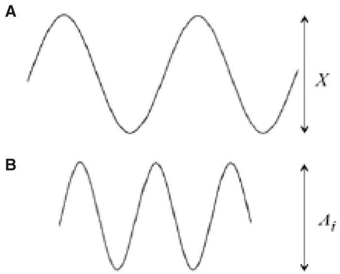
With regard to the frequency responses, Table 102.107 of the Particular Requirements30 specifies the minimum characteristics required for the system of response to incoming sinusoidal signals (Test A, B, C, and D) and incoming triangular signals (Test E) . The tests with sinusoidal signals are reasonable and accepted for analogical systems, while for the digital systems that include a pre-processing of the signals these tests are at times not recommended. For this reason, the Particular Requirements introduced a test with triangular waveforms,31 which are more suitable to digital technologies and recommended by test protocols. A performance test protocol of an electrocardiograph aiming to demonstrate an accurate reproduction of the bandpass signal, needs to provide an input sinusoidal signal of nominal amplitude 1 mV, with frequencies ranging between 0.67 Hz and 40 Hz and ascertain the conformity to specifications of Test A of Table 201.107; the aim is to verify, therefore, that the amplitude of the output signal is equal to the output amplitude generated by an input sinusoidal signal of 10 Hz (amplitude1 mV) at less than an admitted tolerance of 10%. The value of 10 Hz is taken as a reference frequency since it is considered a central frequency, that is, which suffers less in the possible decrease due to the frequency response band.
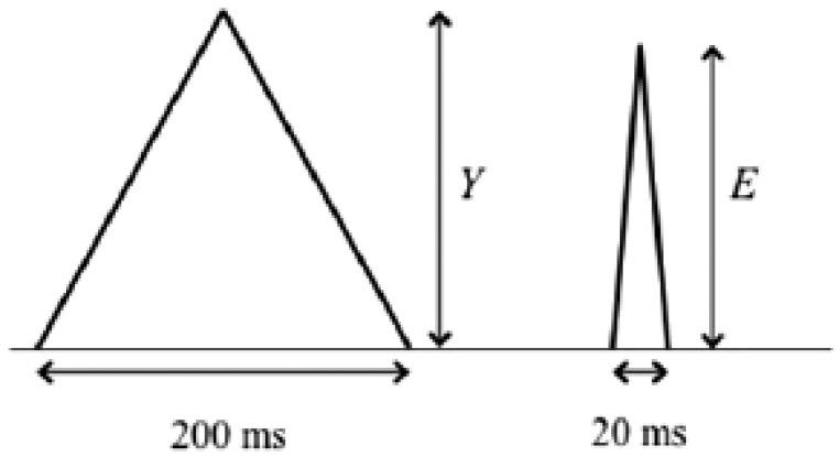
In order to guarantee that rapid high frequency contributions are reproduced in an adequate manner, it would be necessary to carry out Test E of Table 102.107: at the input of the electrocardiograph, a triangular signal with 200 ms of base width, frequency ≤ 1 Hz and nominal amplitude of 1.5 mV is supplied, and conformity is ascertained by verifying that the amplitude of the electrocardiograph’s output signal is not reduced to less than 90% (maximum reduction of 10%) when a triangular analogical impulse is applied, but with a width of 20 ms (Figure 19).
Figure 19.
(A) Sinusoid at 10 Hz. (B) greater frequency sinusoid.
The characteristics of the triangular wave are very similar to those of the QRS complex and are, therefore, more suitable for an analysis of the high frequency response of an electrocardiograph (Figure 20).
Figure 20.
Triangular impulses of 200 ms and 20 ms width.
The 10% reduction allowed is based on the theoretical calculations and bench tests to enable the comparison between the performances of an electrocardiograph and those of other linear systems with band widths up to 150 Hz.
Similar tests are indicated also in the ECG monitoring norms and in those for Holter systems. For both monitors and Holter systems, in the test with sinusoid samples the reduction of the signal with frequencies 0.67 to 40 Hz can reach 30%. Likewise, since the cut-off frequency can be less as, with monitors having only ‘concise diagnostic purposes’, the reduction of the amplitude of the triangular wave may be up to 30% by applying a wave width of 40 ms, compared with the reference wave with 200 ms width. This test corresponds to verifying a minimum bandwidth of 40 Hz.
For the Holter systems, the test is similar to that of monitors, thus with bandwidth equivalence still at 40 Hz. But the norm prescribes that if the producers declare that the system may be used on paediatric patients of less than 10 kg, the reduction of the triangular wave amplitude must not be greater than 20% with a wave form of 40 ms, corresponding to a band width of 55 Hz.
The different tests (A and E), in accordance with international norms must be conducted by setting the electrocardiograph at the maximum band available, removing all the filters with a sensitivity equivalent to 10 mm/mV and direct writing speed equal to 25 mm/s.
Note that the norm does not provide criteria for the conformity test with bandwidth of 250 Hz. In experimental tests conducted on equipment that declared such a bandwidth, however, the reduction of the triangular wave amplitude of 20 ms in width compared with the sample with 200 ms is more or less null.
The low frequency response was traditionally defined in terms of low frequency cut-off of 0.05 Hz, which was considered sufficient to achieve an accurate reproduction of the ST segment also for a 1st-order filter with unspecified response phase. Currently more sophisticated filters are used, that potentially give a reproduction that is equally accurate at the ST segment level and is an adequate reproduction of the inclination though with higher cut-off frequency, allowing in fact a more rapid recovery of the baseline.
Therefore, on the basis of the AHA recommendations of 1990 and 20072,8,10,13 the prescriptions for the low frequency response are not defined in terms of prescriptions for impulsive response.32 Norm IEC 601-2-25 repeats this recommendation and the compliance with the prescriptions specified 201.12.4.107.1.1.2 of the norm is enough to guarantee that the device being analysed is able to reproduce ST segment (and of the low frequency components in general) adequately.
The electrocardiograph is given an input impulse of 300 μVs (e.g. a rectangular impulse of 3 mV in amplitude and 100 ms duration or another equivalent impulse) and this signal must not produce an isoelectric offset greater than 100 μV on the recording and should not produce an inclination greater than 300 μV/s in the zone following the impulse, if a normal sensitivity is set (10 mm/mV and a running speed of 25 mm/s) (Figure 21).
Figure 21.
Rectangular impulse with an offset from the isoelectric and inclination of the isoelectric pendenza, gradient.
The immediate reading of the test could be simplified as follows:
an offset of the isoelectrical line of 100 μV is equivalent to about 1 mm on the recording, considering possible sensitivity errors;
an inclination of 300 μV/s indicates, for example, that in the 200 ms = 5 mm following the impulse (0.2 s 25 mm/s = 5 mm), the recording must not vary more than 60 μV. In fact, 300 μV/s (inclination) ÷ 25 mm/s (paper speed) = 12 μV/mm, which multiplied by 5 mm gives the value of 60 μV, which is equal to 0.6 mm at a normal sensitivity, a bit more than half a square of ECG paper.
Since, as we have seen, the prescription contained in international articles and recommendations over the last years confirm that the marked distortions of the ST segment expected with an improper cut-off frequency at the low frequencies can be partially modulated by modern digital electrocardiographs on condition that one accepts the introduction of a delay between signal acquisition and printout (computer-processed elaboration), the test protocol will admit that the response tests in low frequency (impulse of 300 μVs) are conducted with the various high-pass filter settings applicable (0.05 Hz, 0.5 Hz or others, according to the manufacturer) in both manual and automatic modes.
The low-pass cut-off frequency will always be set at 150 Hz.
The tests conducted in manual mode will, on one hand, serve to verify that the possible filterings of the high-pass type with cut-off frequency ≤0.05 Hz do not distort the waveform, and on the other hand, to check whether the other types of high-pass filterings applicable (with greater cut-off frequencies), that in any case not recommended in clinical practice, will distort the signal or not. On the contrary, the tests conducted in automatic mode will serve to establish the value up to which the high-pass cut-off frequency can be extended in the frequency interval ranging between 0.05 (captured on the patient with physical amplification) and 0.67 Hz (in case of acquisition on a demo PC) (according to international recommendations it is correct to affirm that, in clinical practice, 0.67 Hz is only a theoretical limit, since there are already strong doubts on the use of 0.5 Hz in automatic mode).
Once verified that the corresponding performances effectively issued by the device conform to the declared data plate and the type of high-pass filterings that can be used in automatic mode, it will be necessary to ensure that such usage indications are complied with in daily practice. A first notation that can facilitate this task on the part of the medical-nursing staff consists in the correct setting of the default filterings, that is, filterings that are preset when the device is turned on. The task of the Hospital Technical Service technicians is to ensure that the default settings comply with norm provisions; this operation should be accessed through a given password only.
It does not suffice that the equipment available conforms to the norm provisions if the know-how is not transferred to the technical staff (Hospital Technical Service) and the end-users of the electrocardiograph, so as to guarantee correct use of the device.
Norm IEC 60601-2-25 in paragraph 201.12.4.105.3 requires that: ‘every setting adjustment on the part of the user may downgrade the performance below the essential requisites defined in the norm, and, when used, must give an indication on the report that the diagnosis may be altered by the placing of filters’. In other words, the report must clearly indicate which filters have been set and the clinician should be informed of the possible deteriorating effects of the filtering. Clear indications on the use of filters should thus be conveyed to the medical-nursing team by the Hospital Technical Service with specific reference also to the indications in the user manual of the device, which should be read by the personnel.
The acquisition of an ECG signal for diagnostics purposes using filtering settings unsuitable to this scope, can cause, on the one hand, a loss of useful information, and on the other, can introduce the possibility to generate distortions in the waveform. For pathological waveforms, these aspects, taken singularly or jointly, increase the probability that the characteristics linked to the pathology are lost or made less evident, while the very same increasing the probabilities, for non-pathological waveforms, of the appearance of completely different features from those introduced by specific pathologies (probability to incur in false negatives and false positives).
Many publications report cases of pathologies that show at ECG waveform level with features that can be modified or concealed by an incorrect interpretation of the signal.
On the basis of the explanations above, it is evident that the use of filters is not advisable, but in many situations it is vital. A filter is generally designed to attenuate or remove some frequencies from input data. The need to apply specific filters to acquired cardiac signals arises from the presence of noise in the signal, a term with which disturbance is generally indicated, overlapping with the signal. This disturbance may be endogenous or exogenous according to whether it arises from a cause inside or outside the organism under examination, correlated to or disconnected from the signal, and is responsible for the generation of ECG signal artefacts, namely, modifications of the signal that are not generated by cardiac activities. The main noises overlapping with an ECG signal can be grouped under the definition of baseline oscillation, network interferences and muscle artefacts.
The oscillations of the baseline consist in a swaying trend of the isoelectric that may have various causes:
bad electrode-skin coupling due to bad preparation of the skin or sweating;
breathing artefacts, responsible for slow periodic oscillations due to diaphragm movements related to breathing, with a frequency of 0.2/0.3 Hz;
patient movement artefacts, that may provoke variations of the electrochemical potentials and hinder polarization in the electrode-skin contact.
Electromagnetic fields related to power supply of the grid may cause sinusoidal interferences of 50 (or 60) Hz, ideally represented in the dominion of frequencies by a spectral line in correspondence with the network frequency. Keeping at a reasonable distance from the power grid, and using an adequate screening and grounding may help to avoid or at least reduce this type of inconvenience. Many devices are equipped with selective filters (notches) that remove only the frequency of 50 Hz. Often the removal of the network artefact is obtained by cutting all the components above 40 Hz, thus jeopardizing the diagnostic quality of the waveform. The clinician must be aware of how the filter operated.
Lastly, activities or skeletal muscle tremors produce electric signals in all ways similar to the cardiac signals and overlap with the ECG signal, giving rise to muscle artefacts. These disturbing signals are not limited to a specific frequency but are problematic in as much as their spectral content overlap mostly with the heart signal between 30 and 200 Hz.
It is evident that by using an ideal filter, we would expect the filter to remove only the noise without altering the desired signal. Unfortunately, noises and signals are often overlapping in the dominion of frequencies: the result is that when a filter attenuates the components in frequency corresponding to the noise, the desired, overlapping signal may be involved in this process, and be distorted in amplitude. Designing a good filter would, therefore, mean finding a good compromise between the minor amplitude distortion of the useful signal and noise reduction, targeting an optimal signal-noise ratio, and minimizing or avoiding phase distortions.
The two main types of filterings in the elaboration process of an ECG signal (excluding the filter for grid interference) correspond to a filter of the high-pass type for the suppression of baseline instability and a low-pass anti-aliasing type of filter.
The function of the high-pass filter (low frequency response) is to eliminate the low frequency baseline oscillations, provoked by different phenomena that have to be removed as much as possible. Moreover, the need to use filters of the high-pass type derives from a technical problem at the electrode-skin interface direct current potentials are generated with amplitude up to 200 mV, with which the cardiac electric signal overlaps by a few millivolts. In order to amplify the signal without saturating the electronic components, it is necessary to eliminate the direct component, by using, precisely, a high-pass filter. A high-pass filter with an inadequate frequency is a potential source of errors for the recording, such as deflections of the ECG signal, particularly of the ST segment and the T wave, in all ways similar to those related to ischaemic episodes.
The function of low-pass filters (high frequency response) is useful in reducing the high frequency noise components due, for example, to muscle tremors and may be responsible for the incorrect reproduction of the QRS complex, since it is in this part of the ECG signal that the higher frequency components are found. An inadequate low-pass frequency, which excessively reduces the bandwidth of the filter, would consequently reduce the amplitude of the QRS complexes and the possibility to capture small deflections. The same effect of amplitude reduction of the simulated triangular wave occurs when the duration is decreased, since the ECG is a complex signal full of information.
The presence of filters that can be set by the operator may, therefore, jeopardize the respondence of waveforms to the criteria described above, making the waveform lose its diagnostic value.
Transmission of the electrocardiogram signal from the region/emergency/out-of-hospital facilities
The remote transmission of the ECG signal is a growing practice that greatly impacts on health care. The emergency network in many areas of our country is based on the transmission of ECGs from emergency services or regional health facilities directly to a reference Intensive Care Unit or Cardiology Department. The early prehospital recognition of myocardial infarction with ST segment elevation can reduce reperfusion times and thus improve patient outcomes. This approach is suggested and recommended by all the guidelines and dealt with in a specific ANMCO/SIT33 consensus document.
The pre-hospital transmission of the ECG, however, implies many critical points concerning the organization and training of emergency staff, the artefacts of the transmitted signal and the interpretation errors, the validity of the transmission system and the compliance with the standards of the ECG digital format. Wherever monitoring can be also performed with 3–7 leads, the ECG that will have to be transmitted must respond to the same specifications for diagnostic ECG. The ECG will thus have to be recorded on 12 leads with a frequency response from 0.05 to 150 Hz. It is obvious that, if for ordinary diagnostics compliance with the aforesaid requisites is mandatory, it is even more important to use suitable devices, materials and measures for the transmission of diagnostic ECGs. Indeed, important, potentially life-saving, clinical decisions are made on the basis of these waveforms. The panel believes it is important that the transmitted ECG always clearly reports both the precise time, place and facility of the test, and the demographics of the patient whose waveform is being transmitted.
Transmission and reporting of out-of-hospital electrocardiogram signals and waveforms
Cost saving in device manufacturing, the size reduction and simplified use of electrocardiographs, the nowadays widespread digitalization of signal, and the increasing awareness of the importance of performing an ECG whenever necessary, have encouraged the diffusion of the use of electrocardiographs outside the hospital and doctor’s office. An example among many is the offer of diagnostic tests directly to GP’s, if not to patients themselves, by companies, private organizations, or pharmaceutical companies. These services may carry out a useful service in support of health care activities.
The offer of ECGs thus becomes, to all effects, a diagnostic test that can be used for diagnosis, comparison with previous results, or be archived. Therefore, it is necessary to regulate this opportunity through recommendations for use that ensure the quality of the diagnostic test and, therefore, the patient’s safety. Undoubtedly, an ECG must have the same qualitative characteristics regardless of where it is taken. A crucial point of this type of service is the possibility to offer the recording of the ECG signal according to quality and safety criteria. To do so, the Panel recommend that the test be recorded in compliance with the quality recommendation described above, exactly like in other facilities. The report, which is carried out after sending the test, will have to be validated by a specialist. The diagnosis must be clearly readable, in compliance with the patient demographics, the place and the time of the test, and the specifications of signal acquisition (filtering). Failure to comply with these instructions will result in the test being discarded as unsuitable for diagnostic purposes.
The digital revolution underway in the world as in our country is witnessing the proliferation of smartphone sensors, Apps, loop recorders (at times integrated among themselves) that are suitable to capture biological signals. The most common among them is an ECG signal of some form, acquired to study cardiac rates and rhythm. It is worth underlining that many of these innovations operate in the perspective of allowing more freedom to the patient; therefore, they imply more difficulty in controlling both the devices, their purposes and uses Albeit these devices can potentially help recognize rhythm disorders, at the moment there are no available certified diagnostic devices for clinical purposes. It would be important that devices for clinical use be certified for that use only, after a careful validation which concerns both technical aspects and the clinical environments where they will be used.
A separate discussion would be needed about ‘wearable’/wireless devices which allow ECG monitoring. The waveform recorded and processed may be conserved as such and transmitted or processed with recognition algorithms for heart rhythm recognition. Subsequently, acquired data may be stored or transmitted via remote transfer.33 Research and development on these diagnostic devices is lively, to ensure the quality of the signal captured so as to maintain the necessary requisites for a diagnostic test.
The same amount of attention must be paid to the developments of telemedicine, which uses the ECG signal or information on cardiac rhythms acquire from any device, including implantable devices such as pacemakers and defibrillators etc. The quality of the signal for diagnostic use obviously concerns the ECG, as with all other clinical applications.
Miscellaneous
This document does not aim to deal with ECG signal storage. Once digitalized, the ECG signal may be archived in various standard formats. Signal acquisition and interpretation depend not only on the modes discussed, but also on the components of the transmission system and how the tracings are stored. This topic will be dealt with specifically in the future. At present there are some standard principles (DICOM3 ECG, HL7aECG, XML-FDA, UNIPRO, and SCP-ECG) for the conservation and retrieval of waveforms. It would be best that the manufacturing companies define a sole non-proprietary standard to which they can jointly agree to comply with, to allow interchange of waveforms and their universal usage.
Conclusions
The use of the ECG signal in whatever way it is recorded requires some technological measures and solutions to ensure quality. To obtain this, it is mandatory to comply with some requirements, well outlined by the international guidelines and standards. Without them, the signal may cause serious problems, resulting in a negative impact on the safety of patients and operators.
Too often ECG signal recording devices are placed on the market without necessary measures, due to the use of less stringent solutions that allow lower prices. Utmost importance is thus given to the choice of the correct signal filtering and sampling, as well as the algorithms for analysis and automatic interpretation of ECGs in the detection of pathologies, which are necessary components of all the devices in question (from electrocardiographs to the most sophisticated telemetry systems).
This document aims to offer a support tool in the choice of these diagnostic devices that are very important in daily life for the care of patients with cardiovascular risk.
Appendix
Consensus Document Approval Faculty
Abrignani Maurizio Giuseppe, Alunni Gianfranco, Amico Antonio Francesco, Amodeo Vincenzo, Angeli Fabio, Aspromonte Nadia, Audo Andrea, Azzarito Michele, Battistoni Ilaria, Bianca Innocenzo, Bisceglia Irma, Bongarzoni Amedeo, Bonvicini Marco, Cacciavillani Luisa, Calculli Giacinto, Canzone Giuseppe, Capecchi Alessandro, Caporale Roberto, Caretta Giorgio, Carmina Maria Gabriella, Casazza Franco, Cassin Matteo, Casu Gavino, Chiarandà Giacomo, Chiarella Francesco, Chiatto Mario, Cibinel Gian Alfonso, Ciccone Marco Matteo, Cicini Maria Paola, Clerico Aldo, Colivicchi Furio, Comoglio Francesca Maria, D’Agostino Carlo, De Luca Giovanni, De Luca Leonardo, De Maria Renata, Del Sindaco Donatella, Di Fusco Stefania Angela, Di Lenarda Andrea, Di Tano Giuseppe, Egidy Assenza Gabriele, Egman Sabrina, Enea Iolanda, Fattirolli Francesco, Francese Giuseppina Maura, Geraci Giovanna, Giardina Achille, Greco Cesare, Gregorio Giovanni, Iacoviello Massimo, Khoury Georgette, Ledda Antonietta, Lucà Fabiana, Macera Francesca, Marini Marco, Mascia Franco, Masson Serge, Maurea Nicola, Maz-zanti Marco, Mennuni Mauro, Menotti Alberto, Menozzi Alberto, Mininni Nicola, Molon Giulio, Moreo Antonella, Moretti Luciano, Mortara Andrea, Mureddu Gian Francesco, Murrone Adriano, Musumeci Giuseppe, Nardi Federico, Navazio Alessandro, Nicolosi Gian Luigi, Oliva Fabrizio, Oreglia Jacopo, Parato Vito Maurizio, Parrini Iris, Patanè Leonardo, Pini Daniela, Pino Paolo Giuseppe, Pirelli Salvatore, Procaccini Vincenza, Pugliese Francesco Rocco, Pulignano Giovanni, Radini Donatella, Rao Carmelo Massimiliano, Rasetti Gerardo, Riccio Carmine, Roncon Loris, Rossini Roberta, Ruggieri Maria Pia, Rugolotto Matteo, Sanna Fabiola, Sauro Rosario, Scalvini Simonetta, Scherillo Marino, Severi Silva, Silvestri Paolo, Sisto Francesco, Tarantini Luigi, Themistoclakis Sakis, Uguccioni Massimo, Urbinati Stefano, Valente Serafina, Vatrano Marco, Vianello Gabriele, and Vinci Eugenio.
Conflict of interest: none declared.
References
- 1. IEC EN 60601-2-25:2011 Medical electrical equipment—Part 2-25: Particular requirements for the basic safety and essential performance of electrocardiographs International Electrotechinical Commission; 2011.
- 2. Kligfield P, Gettes LS, Bailey JJ, Childers R, Deal BJ, Hancock EW, van Herpen G, Kors JA, Macfarlane P, Mirvis DM, Pahlm O, Rautaharju P, Wagner GS American Heart Association Electrocardiography and Arrhythmias Committee, Council on Clinical Cardiology American College of Cardiology Foundation Heart Rhythm Society Josephson M, Mason JW, Okin P, Surawicz B, Wellens H.. Recommendations for the standardization and interpretation of the electrocardiogram: part I: The electrocardiogram and its technology: a scientific statement from the American Heart Association Electrocardiography and Arrhythmias Committee, Council on Clinical Cardiology; the American College of Cardiology Foundation; and the Heart Rhythm Society: endorsed by the International Society for Computerized Electrocardiology [Review]. Circulation 2007;115:1306–1324. [DOI] [PubMed] [Google Scholar]
- 3. Schwartz PJ, Breithardt G, Howard AJ, Julian DG, Ahlberg NR.. The legal implications of medical guidelines—a Task Force of the European Society of Cardiology. Eur Heart J 1999;20:1152–1157. [DOI] [PubMed] [Google Scholar]
- 4. Buendía-Fuentes F, Arnau-Vives MA, Arnau-Vives A, Jiménez-Jiménez Y, Rueda-Soriano J, Zorio-Grima E, Osa-Sáez A, Martínez-Dolz LV, Almenar-Bonet L, Palencia-Pérez MA.. High-bandpass filters in electrocardiography: source of error in the interpretation of the ST segment. ISRN Cardiol 2012;2012:706217. [DOI] [PMC free article] [PubMed] [Google Scholar]
- 5. Nakagawa M, Tsunemitsu C, Katoh S, Kamiyama Y, Sano N, Ezaki K, Miyazaki H, Teshima Y, Yufu K, Takahashi N, Saikawa T.. Effect of ECG filter settings on J-waves. J Electrocardiol 2014;47:7–11. [DOI] [PubMed] [Google Scholar]
- 6. Priori SG, Blomström-Lundqvist C, Mazzanti A, Blom N, Borggrefe M, Camm J, Elliott PM, Fitzsimons D, Hatala R, Hindricks G, Kirchhof P, Kjeldsen K, Kuck KH, Hernandez-Madrid A, Nikolaou N, Norekvål TM, Spaulding C, Van Veldhuisen DJ.. 2015 ESC Guidelines for the management of patients with ventricular arrhythmias and the prevention of sudden cardiac death: The Task Force for the Management of Patients with Ventricular Arrhythmias and the Prevention of Sudden Cardiac Death of the European Society of Cardiology (ESC). Endorsed by: Association for European Paediatric and Congenital Cardiology (AEPC). Eur Heart J 2015;36:2793–2867. [DOI] [PubMed] [Google Scholar]
- 7. Sornmo L, Laguna P.. Electro-Cardiogram (ECG) Signal Processing. Hoboken, NJ: Wiley Encyclopedia of Biomedical Engineering, John Wiley & Sons, Inc; 2006. [Google Scholar]
- 8. Turakhia MP, Estes NA 3rd, Drew BJ, Granger CB, Wang PJ, Knight BP, Page RL; Electrocardiography and Arrhythmias Committee of the American Heart Association Council on Clinical Cardiology and Council on Cardiovascular Nursing. Latency of ECG displays of hospital telemetry systems: a science advisory from the American Heart Association. Circulation 2012;126:1665–1669. [DOI] [PubMed] [Google Scholar]
- 9.ANSI/AAMI EC57:2012. Testing and Reporting Performance Results of Cardiac Rhythm and ST Segment Measurement Algorithms Association for the Advancement of Medical Instrumentation; 2012.
- 10. Batchvarov VN, Brown S.. Limitations of modern programs for automatic electrocardiogram inter-pretation. J Electrocardiol 2011;44:250.. [DOI] [PubMed] [Google Scholar]
- 11. Hwan Bae M, Hoon Lee J, Heon Yang D, Sik Park H, Cho Y, Chull Chae S, Jun JE.. Erroneous computer electrocardiogram interpretation of atrial fibrillation and its clinical consequences. Clin Cardiol 2012;35:348–353. [DOI] [PMC free article] [PubMed] [Google Scholar]
- 12. Clark EN, Sejersten M, Clemmensen P, Macfarlane PW.. Automated electrocardiogram interpretation programs versus cardiologists’ triage decision making based on teletransmitted data in patients with suspected acute coronary syndrome. Am J Cardiol 2010;106:1696–1702. [DOI] [PubMed] [Google Scholar]
- 13. Mason JW, Hancock EW, Gettes LS, Bailey JJ, Childers R, Deal BJ, Josephson M, Kligfield P, Kors JA, Macfarlane P, Pahlm O, Mirvis DM, Okin P, Rautaharju P, Surawicz B, van Herpen G, Wagner GS, Wellens H; American Heart Association Electrocardiography and Arrhythmias Committee, Council on Clinical Cardiology; American College of Cardiology Foundation; Heart Rhythm Society. Recommendations for the standardization and interpretation of the electrocardiogram: part II: electrocardiography diagnostic statement list a scientific statement from the American Heart Association Electrocardiography and Arrhythmias Committee, Council on Clinical Cardiology; the American College of Cardiology Foundation; and the Heart Rhythm Society Endorsed by the International Society for Computerized Electrocardiology [Review]. J Am Coll Cardiol 2007;49:1128–1135. [DOI] [PubMed] [Google Scholar]
- 14. Surawicz B, Childers R, Deal BJ, Gettes LS, Bailey JJ, Gorgels A, Hancock EW, Josephson M, Kligfield P, Kors JA, Macfarlane P, Mason JW, Mirvis DM, Okin P, Pahlm O, Rautaharju PM, van Herpen G, Wagner GS, Wellens H; American Heart Association Electrocardiography and Arrhythmias Committee, Council on Clinical Cardiology; American College of Cardiology Foundation; Heart Rhythm Society. AHA/ACCF/HRS recommendations for the standardization and interpretation of the electrocardiogram: part III: intraventricular conduction disturbances: a scientific statement from the American Heart Association Electrocardiography and Arrhythmias Committee, Council on Clinical Cardiology; the American College of Cardiology Foundation; and the Heart Rhythm Society. Endorsed by the International Society for Computerized Electrocardiology [Review]. J Am Coll Cardiol 2009;53:976–981. [DOI] [PubMed] [Google Scholar]
- 15. Wagner GS, Macfarlane P, Wellens H, Josephson M, Gorgels A, Mirvis DM, Pahlm O, Surawicz B, Kligfield P, Childers R, Gettes LS, Bailey JJ, Deal BJ, Gorgels A, Hancock EW, Kors JA, Mason JW, Okin P, Rautaharju PM, van Herpen G; American Heart Association Electrocardiography and Arrhythmias Committee, Council on Clinical Cardiology.; American College of Cardiology Foundation.; Heart Rhythm Society. AHA/ACCF/HRS recommendations for the standardization and interpretation of the electrocardiogram: part VI: acute ischemia/infarction: a scientific statement from the American Heart Association Electrocardiography and Arrhythmias Committee, Council on Clinical Cardiology; the American College of Cardiology Foundation; and the Heart Rhythm Society. Endorsed by the International Society for Computerized Electrocardiology [Review]. J Am Coll Cardiol 2009;53:1003–1011. [DOI] [PubMed] [Google Scholar]
- 16. Hancock EW, Deal BJ, Mirvis DM, Okin P, Kligfield P, Gettes LS, Bailey JJ, Childers R, Gorgels A, Josephson M, Kors JA, Macfarlane P, Mason JW, Pahlm O, Rautaharju PM, Surawicz B, van Herpen G, Wagner GS, Wellens H; American Heart Association Electrocardiography and Arrhythmias Committee, Council on Clinical Cardiology.; American College of Cardiology Foundation.; Heart Rhythm Society. AHA/ACCF/HRS recommendations for the standardization and interpretation of the electrocardiogram: part V: electrocardiogram changes associated with cardiac chamber hypertrophy: a scientific statement from the American Heart Association Electrocardiography and Arrhythmias Committee, Council on Clinical Cardiology; the American College of Cardiology Foundation; and the Heart Rhythm Society. Endorsed by the International Society for Computerized Electrocardiology [Review]. J Am Coll Cardiol 2009;53:992–1002. [DOI] [PubMed] [Google Scholar]
- 17. International Standard IEC 60601-2-51: 2003-02. Medical Electrical Equipment–Part 2-51: Particular requirements for the safety, including essential performance, of recording and analysing single channel and multichannel electrocardiographs, Switzerland: International Electrotechnical Commission. [Google Scholar]
- 18. Luo S, Johnston P.. A review of electrocardiogram filtering. J Electrocardiol 2010;43:486–496. [DOI] [PubMed] [Google Scholar]
- 19. Kligfield P, Okin PM.. Prevalence and clinical implications of improper filter settings in routine electrocardiography. Am J Cardiol 2007;99:711–713. [DOI] [PubMed] [Google Scholar]
- 20. Berson AS, Pipberger HV.. The low-frequency response of electrocardiographs, a frequent source of recording errors. Am Heart J 1966;71:799–789. [DOI] [PubMed] [Google Scholar]
- 21. Bragg-Remschel DA, Anderson CM, Winkle RA.. Frequency response characteristics of ambulatory ECG monitoring sys- tems and their implications for ST segment analysis. Am Heart J 1982;103:20–31. [DOI] [PubMed] [Google Scholar]
- 22. Tayler DI, Vincent R.. Signal distortion in the electrocardiogram due to inadequate phase response. IEEE Trans Biomed Eng 1983;30:352–356. [DOI] [PubMed] [Google Scholar]
- 23. Tayler DI, Vincent R.. Artefactual ST segment abnormalities due to electrocardiograph design. Br Heart J 1985;54:121–128. [DOI] [PMC free article] [PubMed] [Google Scholar]
- 24. Bailey JJ, Berson AS, Garson A Jr, Horan LG, Macfarlane PW, Mortara DW, Zywietz C.. Recommendations for standardization and specifications in automated electrocardiography: bandwidth and digital signal processing. A report for health professionals by an ad hoc writing group of the Committee on Electrocardiography and Cardiac Electrophysiology of the Council on Clinical Cardiology, American Heart Association. Circulation 1990;81:730–9. [DOI] [PubMed] [Google Scholar]
- 25. Berson AS, Pipberger HV.. Electrocardiographic distortions caused by inadequate high-frequency response of direct-writing electrocardiographs. Am Heart J 1967;74:208–218. [DOI] [PubMed] [Google Scholar]
- 26. Kossmann CE, Brody DA, Burch GE, Hecht HH, Johnston FD, Kay C, Lepeschkin E, Pipberger HV, Pipberger HV, Baule G, Berson AS, Briller SA, Geselowitz DB, Horan LG, Schmitt OH.. Recommendations for standardization of leads and of specifications for instruments in electrocardiography and vectorcardiography. Circulation 1967;35:583–602. [DOI] [PubMed] [Google Scholar]
- 27. Langner PH Jr, Geselowitz DB, Mansure FT.. High-frequency components in the electrocardiograms of normal subjects and of patients with coronary heart disease. Am Heart J 1961;62:746–755. [DOI] [PubMed] [Google Scholar]
- 28. Braida S, Ventimiglia V.. Risposta in frequenza di un elettrocardiografo a scopo diagnostico: scelta, verifica e corretto utilizzo Documento AIIC; 2014.
- 29. The CSE Working Party. Recommendations for measurement standards in quantitative electrocardiography. Eur Heart J 1985;6:815–825. [PubMed] [Google Scholar]
- 30. International Standard IEC 60601-2-25: 2011-10. Medical Electrical Equipment Part 2-25: Particular requirements for the basic safety and essential performance of electrocardiographs. Switzerland: International Electrotechnical Commission. [Google Scholar]
- 31. Bailey JJ. The triangular wave test for electrocardiographic devices: a historical perspective. J Electrocardiol 2004;37:71–73. [DOI] [PubMed] [Google Scholar]
- 32. Gibinski P, Owczarek A.. Assessment of low frequency response of ECG record ers in relation to international requirements. J Med Inf Technolog 2002;4:63–72. [Google Scholar]
- 33. Baig MM, Gholamhosseini H, Con-Nolly MJ.. A comprehensive survey of wearable and wireless ECG monitoring systems for older adults. Med Biol Eng Comput 2013;51:485–495. [DOI] [PubMed] [Google Scholar]


